


ASSEMBLY AND USER GUIDE
www.crystalscreens.com
Models: S80V2.5P, S92V2.5P, S100V2.5P, S106V2.5P, S80V2.5C, S92V2.5C,
S100V2.5C, S106V2.5C
Record the model and serial number of your Crystal Screen for future
reference. This information is located on the rear of the frame assembly.
Mode:#_______________________________________________________
Serial #:_______________________________________________________

2 | Crystal Screens Assembly and User Guide
IMPORTANT SAFETY INSTRUCTIONS
The exclamation point within an equilateral triangle is intended to alert the
user to the presence of important operation and maintenance (servicing)
instructions in the literature accompanying the appliance.
When using your projection screen, basic safety precautions should always be
followed, including the following:
1. Read and understand all instructions before using.
2. Close supervision is necessary when any appliance is used by or near children.
Do not leave any appliance unattended while in use.
3. The use of an accessory attachment not recommended by the manufacturer
may cause a risk of injury to persons.
4. This projection screen is intended to be mounted on a wall or other solid,
stable vertical surface.
THIS UNIT MUST BE SECURELY MOUNTED BEFORE USE! DO NOT USE UNTIL
MOUNTED AS SPECIFIED IN THIS GUIDE. IMPROPER MOUNTING MAY CAUSE
SERIOUS INJURY OR DEATH.
5. Follow the assembly instructions provided in this guide.
6. Use only the wall mount provided with the screen, or one recommended by
the manufacturer and carefully follow the mounting instructions.
Do not allow children to climb on or play with this product. Do not place
frame on furniture that could tip over and cause injury. This product is
intended to be mounted on a wall surface. Care should be taken to ensure
that children cannot climb on or attempt to play with the screen and/or
frame. Crystal Screens strongly recommends that mounting be performed
by a professional installer.
A minimum of two people is required for proper installation. If you choose
to mount the screen, use the mount supplied by the manufacturer and
follow these instructions. If you have any doubts about your ability to safely
install this frame, contact the retailer or dealer from which it was purchased.
Make sure that the wall where you are mounting this frame can support the
weight. The included wall mount is designed for standard drywall.

CRYSTAL SCREENS ASSEMBLY AND USER GUIDE
Crystal Screens Assembly and User Guide | 3
Warning: To avoid danger of choking or suocation, keep any plastic bags
contained with this product away from babies and children.
3D Warning!
1. Some viewers may experience various types of discomfort during or after viewing 3D
visual images including symptoms like dizziness, disorientation, eye strain/fatigue, blurry
vision, headaches and/or nausea. If a viewer notices any of these or other symptoms of
discomfort while using the screen to view 3D visual images, the aected viewer should
immediately stop watching the screen until symptoms have disappeared for at least 30
minutes. If any such symptoms are particularly severe or persist for hours or days after
using the TV to view 3D visual images, the aected viewer should consult a qualied
physician.
2. It is strongly recommended that individuals with epilepsy, people with history (or family
history) of seizures, individuals with heart disease, pregnant women, and anyone who
becomes nauseated easily should refrain from using the screen to view 3D visual images
unless they have consulted with a qualied physician.
3. Children and teenagers should be carefully supervised while viewing 3D imagery.
Because the visual development of children 6 years and younger may be incomplete and
could be adversely aected by exposure to 3D visual images, it is not recommended that
they use the screen to view 3D visual images unless their parent or guardian has rst
consulted with a qualied physician.
4. Using the screen to view 3D visual images for extended periods of time is not
recommended, even if none of the above symptoms have been experienced. All viewers
should take regular breaks from such viewing.
Recycle Responsibly: This product can be recycled. For product recycling and disposal
information, contact your local government agency or https://www.cta.tech/ConsumerResources/Greener-Gadgets.aspx, www.eRecycle.org (in California), the Electronic
Industries Alliance at www.ecycyclingcentral.com (in the U.S.), or the Electronic Product
Stewardship Canada at www.epsc.ca (in Canada).
Warranty: Crystal Screens comes with a 1-year limited warranty on manufactured
defective parts.
Inside the Package: The following pages contain a list of parts required to assemble
the screen. Please ensure that all parts are included. If any part is missing or damaged,
contact Crystal Screens.

4 | Crystal Screens Assembly and User Guide
A. Bottom Tube x1 B. Side Support Tube x1
C. Top Tube x1 D. Top Tension Tube X1
E. Bottom Tension Tube x1 F. Guide Support x1

CRYSTAL SCREENS ASSEMBLY AND USER GUIDE
Crystal Screens Assembly and User Guide | 5
G. Center Post x2 H. Tension Support Tube x1
I. Center Bracket x8 J. Sliding Corner Bracket x4
K. Spring Guide Assembly x3 L. Compression Spring x3
6 | Crystal Screens Assembly and User Guide
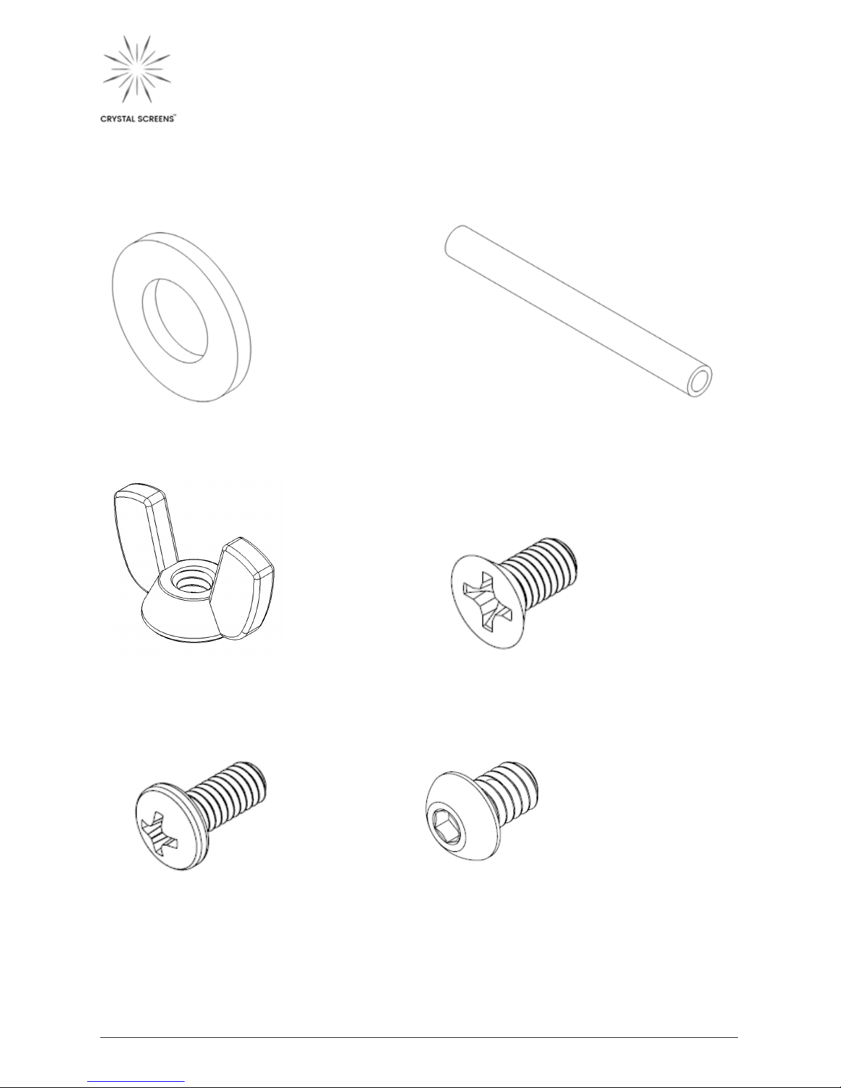
M. Nylon Flat Washer x3 N. Adjustment Tube x3
O. Wing Nut, ¼”-20 x3 P. Phillips Flat-head Screws 10-32 x
3/8” x3
Q. Pan Head Phillips Screws 10-32 x
3/8” x3
R. Button-head Socket Cap Screws
¼-20 x 3/8” x3

CRYSTAL SCREENS ASSEMBLY AND USER GUIDE
Crystal Screens Assembly and User Guide | 7
S. Pan Head Phillip Screws (small) x3
T. Pan Head Phillips Screws 8-32 x 3/8”
x3
U. Metal Washers x3
V. Two Screen Pressure Strips x3

8 | Crystal Screens Assembly and User Guide
FRAME
ASSEMBLY
INSTRUCTIONS

CRYSTAL SCREENS ASSEMBLY AND USER GUIDE
Crystal Screens Assembly and User Guide | 9
Congratulations on purchasing the most technologically
advanced projection screen in the world. Please take a
moment to review these assembly instructions. Neither
Crystal Screens nor Luminit LLC will be held responsible for
faulty installation. To avoid ngerprints, leave the screen
inside of the protective tube until the frame has been
assembled. Fingerprints will not aect the projected
image. When handling the screen, wear the included gloves
to minimize contact with the front side (gray, matted side) of
the Crystal Screen.
NOTE: When laying out the frame, take special care to face
the tubes in the correct direction as noted by the diagrams.
Tubes with holes should be positioned on the same side.

10 | Crystal Screens Assembly and User Guide
1
Insert Side Support Tube (B) into
Bottom Tube (A) and fasten with 2
Phillips Flat Head Screws (P).
NOTE: Side support tubes should
be installed facing outward. These
two tubes can be identied by the
multiple screw holes on the
outer side.

CRYSTAL SCREENS ASSEMBLY AND USER GUIDE
Crystal Screens Assembly and User Guide | 11
2
Insert Top Tube (C) into Side
Support Tube (B) and fasten it with
2 Phillips Flat Head Screws (P).

12 | Crystal Screens Assembly and User Guide
3
Insert Top Tension Tube (D) into Top
Tube (C) and fasten with 4 Phillips
Flat Head Screw

CRYSTAL SCREENS ASSEMBLY AND USER GUIDE
Crystal Screens Assembly and User Guide | 13
4
Insert Bottom Tension Tube (E) into
Bottom Tube (A) and fasten it with 4
Phillips Flat Head Screws (P).

14 | Crystal Screens Assembly and User Guide
5
Fasten the Guide Support (F) to the
top and bottom frames (D) and (E)
using 2 Pan-head Phillips Screws (Q)
on eachend.

CRYSTAL SCREENS ASSEMBLY AND USER GUIDE
Crystal Screens Assembly and User Guide | 15
6
Attach the Center Posts (G) to the
inside of the frame by fastening
them with the Center Brackets (I)
and Pan-head Phillips Screws (T) at
each end. Include Metal Washers
(U). Be sure that both center posts
are installed with mounting holes
facing the same direction as the side
bars, see illustration above.
NOTE: Make sure that holes are
located on the same side!

16 | Crystal Screens Assembly and User Guide
7
Insert the short end of the Sliding
Corner Brackets (J) to each end of
the Tension Support Tube (H) and
fasten each side with Phillips Flat
Head Screws (P).

CRYSTAL SCREENS ASSEMBLY AND USER GUIDE
Crystal Screens Assembly and User Guide | 17
8
Screw the 3 Spring Guide
Assemblies (K) into the Tension
Support Tube (H). Tighten the
Jam Nut completely to lock the
3 Spring Guide Assemblies into
place – you may need to adjust the
thumb screw in order to tighten the
Jam Nuts. Once the Jam Nut is in
position, tighten the thumb screw
so that it is touching the jam nut, as
shown in the illustration above.

18 | Crystal Screens Assembly and User Guide
9
Place a Nylon Flat Washer (M) and
a Compression Spring (L) onto each
of the Spring Guide Assemblies (K).
Carefully insert the assembly from
step 8 into the frame from step
6 through the pre-inserted nylon
ange bearings.

CRYSTAL SCREENS ASSEMBLY AND USER GUIDE
Crystal Screens Assembly and User Guide | 19
10
Place an Adjustment Tube (N)
over each of the 3 Spring Guide
Assemblies (K) and tighten each
evenly with a Wing Nut (O) until
the springs are COMPRESSED
to prepare for Crystal
Screenmounting.

20 | Crystal Screens Assembly and User Guide
CRYSTAL SCREEN
MOUNTING

CRYSTAL SCREENS ASSEMBLY AND USER GUIDE
Crystal Screens Assembly and User Guide | 21
NOTE: Handle the Crystal Screen
carefully. To avoid ngerprints, wear
gloves (Latex, nitrile, cloth, etc.) to
minimize contact with the front side
(gray, matted side) of the Crystal
Screen. (Note: ngerprints will not
aect the projected image.)

22 | Crystal Screens Assembly and User Guide
1
Clean frame of debris. Lay the frame
backside down (mounting holes
faced down), then carefully lay the
Crystal Screen material face up
(glossy side down, grey-matted side
up) on the front side of the frame.
NOTE: The screen is folded on the
left and right sides and includes
pre-drilled holes to secure it to the
frame. You will need to carefully
line up the screen holes with the
threaded frame holes. The screen
is mounted in between the metal
frame and the pressure strips.

CRYSTAL SCREENS ASSEMBLY AND USER GUIDE
Crystal Screens Assembly and User Guide | 23
2
Line up the screen holes on the
material with the threaded frame
holes on the frame. Place a screen
pressure strip (V) over the screen
holes and fasten with Button-head
Socket Cap Screws (R). Before
fastening, make sure the holes on
the folded sides of the screen line
up with the top or bottom edges of
the frame. Do not allow material to
fold or wrinkle.

24 | Crystal Screens Assembly and User Guide
3
Repeat fastening on the opposite
end of the frame as done in Step
2. Line up the screen holes with
threaded frame holes. Place a
pressure strip (V) over the screen
holes and fasten with Buttonhead Socket Cap Screws (R). While
fastening make sure the crease of
the screen lines up with the top or
bottom edges of the frame.
NOTE: If the crease does not match
up, do not force it. Reexamine
the Spring Guide Assemblies
to be certain that each Thumb
Screw is adjacent to its respective
Jam Nut, and each Wing Nut has
been screwed to fully compress
thespring.

CRYSTAL SCREENS ASSEMBLY AND USER GUIDE
Crystal Screens Assembly and User Guide | 25
4
Loosen the Wing Nuts to begin
tensioning the Crystal Screen.
Springs should decompress. Wing
Nuts should be loosened as much
as possible without falling o.

26 | Crystal Screens Assembly and User Guide
5
Tighten the thumb screw until
springs are fully compressed and
the screen is fully tensioned and
free of wrinkles.
NOTE: If you still see creases or
winkles, refer to the troubleshooting
guide at the end of this manual.

CRYSTAL SCREENS ASSEMBLY AND USER GUIDE
Crystal Screens Assembly and User Guide | 27
6
The bezel fastens with 18 Pan Head
Philip Screws Small (S). Ensure the
front of the bezel hooks over the
screen side rst then aligns with
the fastening holes on the back side
of the frame. Note: The six bezel
pieces are marked, 2 for each side, 2
for the top, and 2 for the bottom.

28 | Crystal Screens Assembly and User Guide
WALL MOUNT COMPATIBILITY
Crystal Screen recommends mounting the frame with the included Z-brackets (2).
Attach the two Z brackets to the visible holes on the support tubes using the Phillips
screws included in the packaging. The frame is also compatible with UL-listed TV wall
mounts wider than 28 inches.
MAINTENANCE & CARE
SCREEN CLEANING INSTRUCTIONS
1. First wipe the aected area with the included microber cleaning cloth.
2. If necessary, dampen the aected area with water and blot, do not rub or wipe,
with the cleaning cloth provided.
3. Allow solution to air dry.
4. Repeat Steps 1 – 3 if needed.
TROUBLESHOOTING
PROBLEM SOLUTION
1. No mounting holes on the center
posts for the wall mounts.
Check to see if the center posts are
installed backwards.
2. Mounting holes on center posts do
not line up.
Check if one center post has been
installed upside down.
3. No mounting holes for the screen
bezel
Check if the screen is mounted on the
correct side
4. Wrinkles on the screen.
Make sure the crease of the screen is
lined up with the top edge of the frame.
Make sure the screen is fully tensioned.
5. Scratches on the screen.
Purchase a new screen at your local
Crystal Screens dealer.
6. Smudges on the screen.
Clean the screen using the
recommended cleaning instructions.

CRYSTAL SCREENS ASSEMBLY AND USER GUIDE
Crystal Screens Assembly and User Guide | 29
SCREEN PLACEMENT & INSTALLATION
GUIDE
Care should be taken to ensure that you experience the best possible image quality.
This includes maximizing the projector’s brightness with the placement of the screen,
and placing the audience at a sucient distance relative to the screen size. The light
from the projector should reect o the center of the screen at an angle that is equal
to the angle created when that light reects o the screen as shown in the image
below.
REFLECTING
SURFACE
INCIDENT
WAVE
PERPENDICULARNORMAL OR
ANGLE OF INCIDENCE
ANGLE OF REFLECTION
REFLECTED
WAVE
30 | Crystal Screens Assembly and User Guide
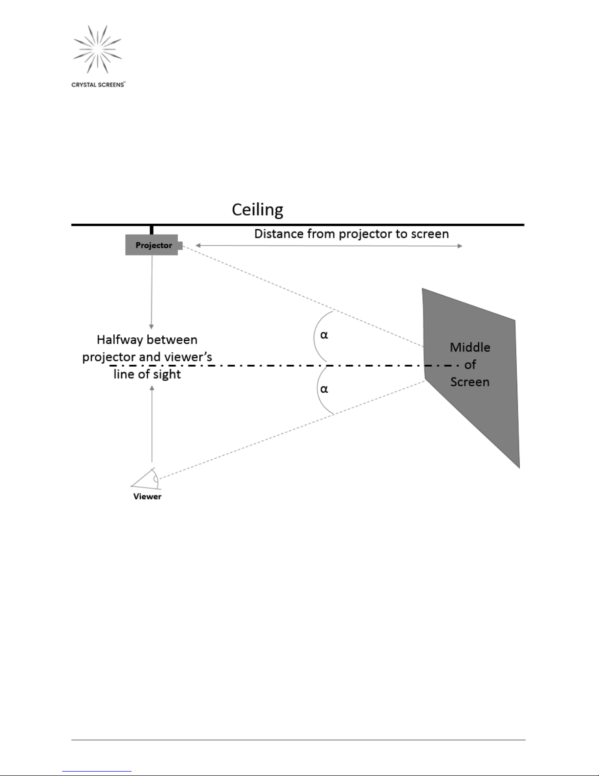
When installing the screen, position it so that the middle (or center) of the screen is
located halfway vertically between the viewer and the projector, when the viewer and
projector are equal distance to the screen.
If viewers are closer than the projector, the screen will need to be lower; conversely, if
viewers are farther than the projector, the screen will need to be higher.

CRYSTAL SCREENS ASSEMBLY AND USER GUIDE
Crystal Screens Assembly and User Guide | 31
PROJECTOR INSTALLATION
Mounting the projector on the ceiling is recommended over a tabletop setup. Many
projectors have a vertical lens shift function that allows the image height to be
adjusted. The projector’s height should be positioned just below the top edge of the
Crystal Screen. Adjust the height of the projector or height of the Crystal Screen until
the top of the projector’s image is slightly below the top edge of the Crystal Screen.
Once in position, the projector lens can be adjusted until the image is ush with the
top edge of the screen. This will create the most favorable viewing experience.
NOTE TO INSTALLERS:
When performing screen material demos, the demo material should always be placed
at a point of incident reection between the viewer and the projector. If the projector
is placed on the oor, ask the viewer to stand up, and place the screen material lower
on the screen.
For more details on screen placement and how to optimize the viewing experience,
visit www.crystalscreens.com
 Loading...