


HPC50 Series
Operation Manual
for the HPC50 Series Intrinsically Safe Handheld Pressure Calibrator
Find Quality Products Online at: sales@GlobalTestSupply.com
www.GlobalTestSupply.com

Contents
Overview...............................................................1
Introduction ............................................................1
Quickstart ..............................................................2
Functions ..............................................................3
On/O..................................................................3
Navigation..............................................................3
Settings ................................................................6
Display .................................................................8
Operation..............................................................9
Pressure Sensors ........................................................9
Measuring Current .....................................................13
Sourcing Current.......................................................14
Measuring Voltage .....................................................15
Measuring Temperature (ATMi) .........................................16
Performing a Switch Test ...............................................17
Calibrating a Pressure Transmitter.......................................18
Enclosure .............................................................20
APMi Modules .......................................................21
ATMi Modules .......................................................22
Specifications .......................................................23
Ranges and Resolutions ................................................28
Safety & Certifications............................................29
Hazardous Locations ...................................................29
Certications ..........................................................29
Multi-language Safety Instructions .....................................30
Support ...............................................................31
Troubleshooting .......................................................31
Calibration ............................................................32
Accessories and Replacement Parts .....................................33
Contact Us.............................................................34
Warranty ..............................................................34
Find Quality Products Online at: sales@GlobalTestSupply.com
www.GlobalTestSupply.com

HPC50 Series Operation Manual
Overview
INTRODUCTION
Thank you for choosing the HPC50 Series intrinsically safe handheld pressure calibrator from Crystal Engineering Corporation. HPC50 calibrators feature dead-
weight tester accuracy in a modern digital package with the safest tting connection available. The full color display features an easy to use interface and may
be used in a broad range of applications fr
om simple tool type jobs to complex calibration jobs in custody transfer systems.
Overview 1
Accuracy is up to 0.035 percent of reading
temperature compensated
Single and dual pressure sensor models are available from vacuum up to 10 000 psi / 700 bar. In addition, the HPC50 features the ability to add up to two
external pressure ports (APMi) to provide up to four pressure ports. When included with a barometric reference (BARO option), all pressure readings can be
displayed as gauge or absolute readings.
In addition to pressure measurement, the HPC50 also includes inputs for mA, voltage, switch testing, and up to two temperature measurement modules (ATMi).
HPC50 Series Measurement Options
Measurement Type Available Modes (as dened on display)
Pressure P1, P2, APMi1, APMi2, Di. Pres, Dual Pres.
Temperature ATM i1, ATM i2
Barometric Pressure BARO
Current mA in
Voltage VDC In
Switch Tes t Switch Tes t
Other features include:
User congurable information display
•
% error calculation
•
% ow calculation
•
Scaling
•
We hope your HPC50 meets your expectations, and we’re interested in any comments or suggestions you may have. You can send us a note at:
crystal@ametek.com. Many features in this and our other products are a direct result of your comments!
– so there is no change in accuracy throughout the entire operating temperature range!
– so one HPC50 can typically replace several gauges or calibrators you may have been using. The HPC50 is fully
Damping
•
Leak Testing
•
Min/Max hold
•
Uses Crystal’s patented CPF ttings and hose system (leak-free and nger-tight to 10 000 psi (700 bar))
•
Crystal Eng
calibrators, and a variety of industry specic pressure measuring equipment.
ineering is the company that designs, manufactures, and services the nVision reference recorders, XP2i series pressure gauges, 30 series pressure
Find Quality Products Online at: sales@GlobalTestSupply.com
www.GlobalTestSupply.com

HPC50 Series Operation Manual
QUICKSTART
APMi and ATMi Module Connections
Connect 1 or 2 external modules to expand measurement
options. The APMi module for pressure, and the ATMi
module for temperature.
“Wireless” Keypad
All input and output
connectors are placed
away from the display and
keypad to give maximum
freedom to operate.
Mini-USB Port
Customize the set-up through
free CrystalControl software.
Function Buttons
The function of each
button is clearly explained
on the bottom of the
display.
Protective Boot
Required for Intrinsic Safety.
Color Display
The large, full-color,
sunproof display
combined with the
advanced simplicity of
the user interface, makes
the HPC50 Series the
easiest-to-use pressure
calibrator available.
Cursor Keys
Cursor keys help you to
navigate through the
display to perform set up
functions and ne tune
values.
Unique “Non-Menu” User Interface
Easy to use single layer user interface. No deep menu structure!
Operate and set up the HPC50 Series to perform your tasks quickly
and intuitively.
Overview 2
CPF Pressure Connections
Includes patented, leak-free, nger-tight
CPF connection ttings.
Find Quality Products Online at: sales@GlobalTestSupply.com
www.GlobalTestSupply.com

HPC50 Series Operation Manual
Functions
ON/OFF
Power button
Press and hold the (power) button to turn the HPC50 Series on or o.
The HPC50 will automatically power down if not used for the time period dened in the unit settings or in CrystalControl.
Automatic Shuto - Low Power Mode
To optimize battery life, adjust your Automatic Shuto time (shut o time in absence of key press) on the unit or through the free
CrystalControl software.
NAVIGATION
Arrow Buttons
Edit Mode: Use the Up and Down
(arrow) buttons to move the cursor one character in the desired direction.
Back Button
This feature is adjustable from 5 minutes to “always on.”
The (arrow) buttons serve dierent functions depending on the mode of operation. Press any of the four (arrow) buttons to enter
“Navigation Mode”. In this mode, the user can scroll through editable elds directly onscreen.
Navigation Mode: Use the four
(arrow) buttons to scroll through lists of options. Or, if entering a number, use the left and right
(arrow) buttons to move the cursor in the desired direction.
Functions 3
Press the (back) button to cancel a selection or to return to a previous menu.
Enter Button
Press the (enter) button to view/accept selected options or entered values. When a value is entered with the (enter) button, the cursor selects
the next value eld in the list.
Find Quality Products Online at: sales@GlobalTestSupply.com
www.GlobalTestSupply.com

HPC50 Series Operation Manual
Zero Button
Press the (zero) button to activate the function key options. The HPC50 will display the parameters that are currently shown on the upper and
lower displays. Press the
zero
Note: If you attempt to zero the gauge with more pressure applied than the Zero Limit set on the HPC50 (or with CrystalControl) the command will be
The BARO sensor cannot be zeroed.
Note:
WARNING: This calibrator can display zero pressure when connected to a source of pressure! Do not rely on the display indication before disconnecting—
!
X
To Clear the Zero Value
1 Press the (zero) button to activate the (function) buttons for the available pressure sensors.
(-----), indicating that it has been zeroed.
ignored, and Over Zero Limit will display.
it may not be indicating true pressure. Never disconnect pressure instrumentation without rst relieving system pressure!
(function) button for the parameter that you would like to zero. The display will then briey ash all dashed lines
Functions 4
2 Press and hold the
X
To Clear the Peaks
1 Press the (zero) button to activate the (function) buttons for the available pressure sensors.
2 Press the
(function) button for Peaks to reset the P1, P2, and APMi peaks.
(function) button for the sensor that you would like to unzero until the display changes from (- - - - -) to (- - -).
Navigating Through a Typical Setup
1 Press any of the (arrow) buttons to enter Navigation Mode.
2 Use the
Note: Congurable elds are not highlighted in light blue on the actual display; but selected elds are highlighted in dark blue.
3 Use the (enter) button to select a eld for editing.
(arrow) buttons to move between the congurable elds within the upper and lower displays.
Find Quality Products Online at: sales@GlobalTestSupply.com
www.GlobalTestSupply.com

HPC50 Series Operation Manual
4 Use the up and down (arrow) buttons to select a new value, then press the (enter) button to choose the new value.
Select a Value… then press enter.
Note: To exit Navigation mode without making a selection, press the (back) button.
Calibration Due Reminder
The HPC50 Series has a calibration reminder feature that can help to assure that you never use the calibrator after its calibration certicate has expired. Set
calibration due dates and warning period through our free CrystalControl software.
X
Calibration Reminder Alert
Enter the Cal Due date and the warning period prior. Once the dened time prior is reached, the HPC50 will ash Cal Soon during the startup process. It will
do this on every start-up until the calibration due date is reached, or the dates are updated.
X
Calibration Due Alert
Once the calibration due date has been reached, the HPC50 will ash Cal Due during start-up. While in use, the HPC50 display will alternate displaying Cal Due
and live pressure readings. This behavior will continue until the calibration date is updated through CrystalControl.
Functions 5
Find Quality Products Online at: sales@GlobalTestSupply.com
www.GlobalTestSupply.com

HPC50 Series Operation Manual
SETTINGS
Settings Button
Press the (settings) button to enter the system settings menu.
X
Recall
Used to recall a saved setup.
X
Save
Used to store the current display setup. Saving a setup allows for quick loading of the same congurations for later use. This makes it easy to switch between
dierent applications or tasks. Up to 5 setups can be stored.
X
General
Used to view or edit the following system settings:
Auto O Time
•
HART resistor On/O
•
Serial Number
•
Firmware Version
•
Part Number
•
Functions 6
X
P1, P2, and APMi
Mode: Switch between absolute and gauge pressure
•
Filter Time
•
Zero Limit
•
Maximum Resolution: When a resolution less than standard is selected, the displayed number will include an asterisk (*)
•
Overpressure Count: Counts the times when pressure has exceeded 110% of the range
•
View Calibration Details
•
Serial Number
•
Part Number
•
Find Quality Products Online at: sales@GlobalTestSupply.com
www.GlobalTestSupply.com

HPC50 Series Operation Manual
X
BARO
Maximum Resolution: When a resolution less than standard is selected, the displayed number will include an asterisk (*)
•
View Calibration Details
•
Serial Number
•
Part Number
•
X
ATMi
Maximum Resolution: When a resolution less than standard is selected, the displayed number will include an asterisk (*)
•
Probe Coecients: Enter and modify RTD coecients
•
View Calibration Details
•
Serial Number
•
X
mA In, mA Out (sink) and VDC In
Maximum Resolution: When a resolution less than standard is selected, the displayed number will include an asterisk (*)
•
View Calibration Details
•
Serial Number
•
X
To Save a Setup
After you have congured the unit, you can save the setup for future use.
Functions 7
1 Press the
2 Press the
3 Press the
4 Use the
The name is limited to eight characters.
Highlight the settings to modify... then change the name of the saved setup.
5 Press the (F3) function button for Save.
(settings) button to enter the settings section.
(arrow) buttons to highlight the Save Setting, and the press the (enter) button.
(arrow) buttons to highlight the setup you want to modify, and then press the (enter) button.
(arrow) buttons to change the name of the saved setup. When nished press the (enter) button.
Find Quality Products Online at: sales@GlobalTestSupply.com
www.GlobalTestSupply.com
HPC50 Series Operation Manual
X
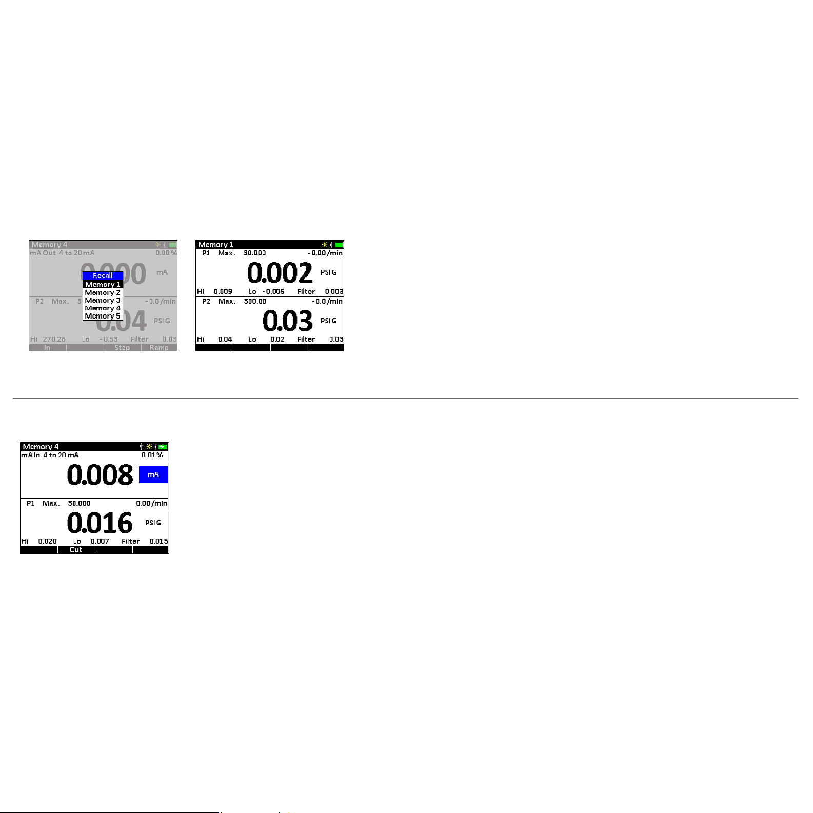
To Recall a Setup
1 Press the (settings) button to enter the settings section.
Functions 8
2 Press the
3 Press the
The name of the setup will appear in the upper-left corner
Highlight the setup… then press enter.
DISPLAY
The display is divided into two sections: the upper and lower displays. The upper display can be congured to show values for Current, Voltage, Temperature,
Pressure, BARO, or Switch Test. The lower display can be congured to show values for only Temperature, Pressure, and BARO.
(arrow) buttons to highlight the Recall Setting, and then press the (enter) button.
(arrow) buttons to highlight the setup you want to use, and then press the (enter) button.
Upper Display (showing Current)
Lower Display (showing Pressure)
Find Quality Products Online at: sales@GlobalTestSupply.com
www.GlobalTestSupply.com

HPC50 Series Operation Manual
Operation
PRESSURE SENSORS
The HPC50 Series is equipped with one or two pressure sensors. In addition, one or two intrinsically safe APMi (Advanced Pressure Module) or ATMi (Advanced
Temperature Module) external modules may also be used. For information on the Crystal external modules, please refer to APMi Modules and ATMi Modules.
Be sure to choose the proper sensor based on working pressures and accuracy.
WARNINGS: The following warnings apply to any sensor used with the HPC50 — whether internal or external:
!
Pressure sensors may be damaged and/or personal injury may occur due to improper application of pressure. Please refer to the
•
Ranges and Resolutions table for information on overpressure ratings.
The calibrator will display
•
to prevent damage or possible personal injury.
Note:
+
OL is displayed when the pressure exceeds 110% of the nominal range of the sensor.
Pressure Connection
Crystal CPF System: Medium Pressure Female (MPF) (1/4” medium pressure tube system with 7/16-20 threads). See our CPF brochure for further information.
+
OL when an inappropriate pressure is applied. If + OL is displayed, the pressure should be reduced or vented immediately
Operation 9
CPF o-ring size and material: AS568A-012, Viton 80 durometer (P/N 3981).
For most applications CPF Fittings can be hand tightened (no tools required). Wrench tightening is recommended (to achieve a metal to metal cone seal) for
applications where chemical compatibility of the process uid and the o-ring are a concern. Cone seals require only moderate assembly torque to seal up to
10 000 PSI (700 bar). We recommend a tightening torque of 120 in-lbs ±20 in-lbs for our CPF ttings. Please note this is only a fraction of the typical torque
required to seal a 1/4” NPT tting. If a torque wrench isn’t practical to use, the ttings can be assembled as follows: Hand tighten tting fully
until the cone has bottomed out, then tighten an additional 20° using a hex wrench. Apply a small amount of media-compatible lubricant to the gland
threads and male cone to incr
CAUTION: To achieve CPF maximum allowable working pressures no o-ring substitutions are allowed. See our CPF brochure and
!
CES-003 CPF Safety Guide available from the website at ametek.com for further detail.
ease tting life, reduce the likelihood of galling, and promote sealing.
Measuring Vacuum
All versions of the HPC50 can be used to measure moderate vacuum.
When measuring pressure less than ambient barometric conditions, a minus (-) sign will appear.
CAUTION: The HPC50 is not recommended for continuous use at high vacuum.
!
Find Quality Products Online at: sales@GlobalTestSupply.com
www.GlobalTestSupply.com
HPC50 Series Operation Manual
Overpressure Conditions
The HPC50 Series will read pressure up to approximately 110% of the rated pressure range. Above 110%, the display will indicate + OL, and readings will stop
+
updating. The zero function does not aect when the display will indicate
without the maximum pressure being displayed.
For instance, if a 100 psi range is zeroed when 30 psi is being applied, it will indicate that the overpressure condition has been reached at 80 psi
(i.e., 110% x 100 psi – 30 psi = 80 psi).
essure can aect accuracy, but the eect is only temporary unless the sensor has been destroyed. See the Ranges and Resolutions table for maximum
Overpr
allowable overpressure ratings.
OL, so depending on the zero value it is possible that the display will indicate + OL
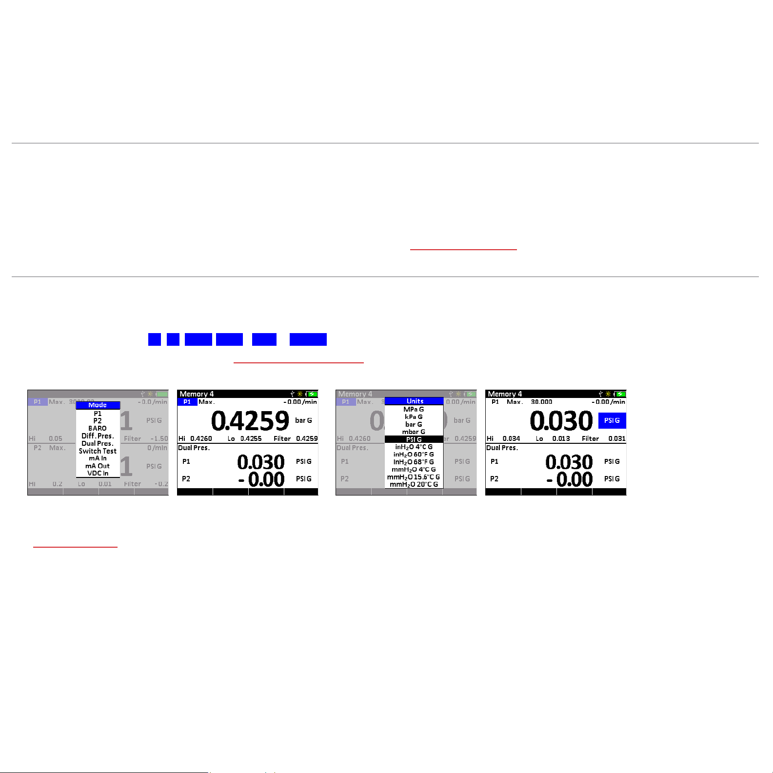
Measuring Pressure
X
To Measure Pressure
1 Connect the HPC50 using an appropriate tting.
2 Select one of the pressure modes: P1 , P2 , APMi1 , APMi2 , BARO , or Dual Pres .
For more information on working in the HPC50 display, see Navigating Through a Typical Setup.
3 From the HPC50 display, select the desired pressure units.
Operation 10
Select a pressure mode... then select a pressure unit.
X
Absolute Pressure (BARO Option)
See P1, P2, APMi1 or APMi2 settings to toggle between absolute and gauge pressure.
Find Quality Products Online at: sales@GlobalTestSupply.com
www.GlobalTestSupply.com

HPC50 Series Operation Manual
X
To Zero the Calibrator
1 Press the (zero) button to activate the (function) buttons for the available pressure sensors.
Operation 11
2 Press the
The display will change to dashed lines (- - - - -) and the reading will be zeroed.
Zeroing the P2 sensor.
X
To Clear the Zero Value
1 Press the (zero) button to activate the (function) buttons for the available pressure sensors.
2 Press and hold the
X
To Clear the Peaks
1 Press the (zero) button to activate the (function) buttons for the available pressure sensors.
2 Press the
3 Press the
(function) button for the sensor that you would like to zero.
(function) button for the sensor that you would like to unzero until the display changes from (- - - - -) to (- - -).
(function) button for Peaks to reset the P1, P2, and APM peaks.
(function) button for the peaks you would like to clear. The Hi, Lo, and Filter will all display (- - - - -).
Note: If you attempt to zero the gauge with more pressure applied than the Zero Limit set on the HPC50 (or with CrystalControl) the command will be
ignored, and Over Zero Limit will display.
The BARO sensor cannot be zeroed.
Note:
WARNING: This calibrator can display zero pressure when connected to a source of pressure! Do not rely on the display indication before disconnecting—
!
it may not be indicating true pressure. Never disconnect pressure instrumentation without rst relieving system pressure!
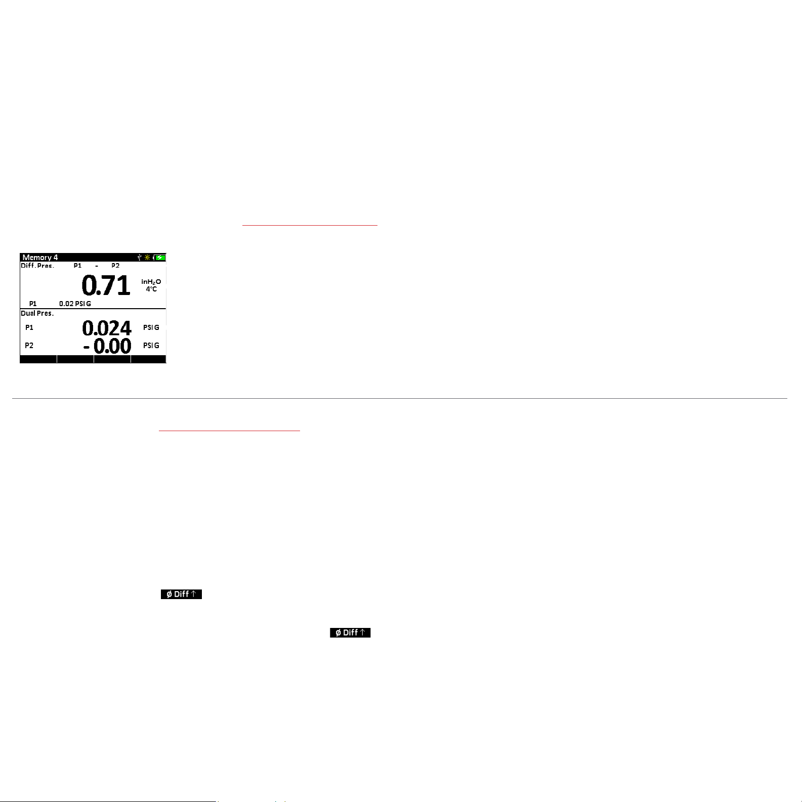
Dierential Pressure
The HPC50 Series can display dierential pressure when 2 or more sensors are installed (including external APMi). The modules do not have to be the same
full scale pressure range.
Find Quality Products Online at: sales@GlobalTestSupply.com
www.GlobalTestSupply.com
HPC50 Series Operation Manual
X
To Display Dierential Pressure
1 Select Di. Pres. from the Mode section.
2 Choose the two sensors that you want to use for dierential pressure.
3 Choose the unit for the dierential reading.
For more information on working in the HPC50 display, see Navigating Through a Typical Setup.
4 Apply pressure to one or both sensors to read the dierential.
The two pressure sensors being used can be changed from P1, P2, or APMi.
Dierential Pressure Unit
Static Pressure Unit
Note: The static pressure is also displayed on the bottom of the window. The unit for the static pressure does not have to be the same as the dierential unit.
Tare
Operation 12
Using the Tare function improves your dierential measurement uncertainty signicantly if used properly. The Tare function equalizes (normalizes) the
HPC50’s two modules at a non-ambient datum.
If you apply the same static line pressure to both sensors simultaneously, you should have a dierential reading of zero. Due to the allowable error tolerance
for each module, the reading may not be zero. The Tare function allows you to normalize both readings so that the dierential reading is zero. This gives you a
more accurate dierential reading than if this process were not completed.
Note: Tare should be reestablished every time your measurement conditions change, including vent condition. For instance if your ΔP reading has 8 inH20 of
Tare at 1500 psi static, when you return to vent condition this 8 inH20 of Tare will remain in place on your ΔP reading until cleared with the Tare button.
To Tare:
1 Use the
2 Press the
3 Press the
Note: You will notice that the word Tare is now included on the top right of the display to indicate that the sensors have been tared.
4 To clear the Tare value in the Dierential Mode, hold the
(arrow) buttons to navigate to the Dierential Mode view.
(zero) button to activate the function button options.
(function) button for the ( ) icon.
(function) button for the ( ) icon for four seconds until the dierential display readings
change from (- - - - -) to (- - -). The tare indication will now be removed from the display.
Find Quality Products Online at: sales@GlobalTestSupply.com
www.GlobalTestSupply.com

HPC50 Series Operation Manual
MEASURING CURRENT
The HPC50 is capable of measuring current in four dierent modes:
mA Measured current is displayed (mA). The module is capable of measuring inputs up to 55 mA.
•
0-20 mA Current is displayed as a percentage of the 0-20 mA current range of the module. Where: 0 mA = 0%, and 20 mA = 100%
•
4-20 mA Current is displayed as a percentage of the 4-20 mA current range of the module. Where: 4 mA = 0%, and 20 mA = 100%
•
10-50 mA Current is displayed as a percentage of the 10-50 mA current range of the module. Where: 10 mA = 0%, and 50 mA = 100%
•
X
To Measure Current
1 Select mA In .
For more information on working in the HPC50 display, see Navigating Through a Typical Setup.
2 In current mode, the numerical value displayed represents the current measured at the test lead inputs. In the top right corner is a percentage value based
on whether 0 to 20 mA , 4 to 20 mA , or 10 to 50 mA is selected.
For example, if the measured current is 16 mA and the selected scale is 4 to 20 mA, the percent will display as 75%.
Operation 13
Measuring Current.
3 Connect the HPC50 using the appropriate test leads.
4 The HPC50 will display the measured current.
Note: The display will indicate
Note: For details on % error, % ow, and scaling features see Percent Error Function.
+
OL if the measured current exceeds the nominal range of current measurement (55 mA).
Find Quality Products Online at: sales@GlobalTestSupply.com
www.GlobalTestSupply.com

HPC50 Series Operation Manual
SOURCING CURRENT
X
mA Sink (External Loop Power Supply)
1 Select mA Out.
2 Select the appropriate range (0-20 or 4-20) if you will be sourcing based on the % of the scale.
3 Choose either mA (to output a specic mA signal), % (to output based on the % of the mA range) , or % ow (to output based on the % of the ow).
4 Connect the HPC50 using the appropriate test lead connections.
5 Enter the desired current in mA, %, or % ow to sink.
X
mA Step
The HPC50 has the ability to automatically or manually step through the mA range at predened intervals.
1 Select mA Out.
2 Select the appropriate mA range (0-20, 4-20).
Operation 14
3 Press the
4 Enter the 0 and 100% mA points. For example, if you’re sourcing to a 4-20 mA loop, enter 4 for the 0% point and 20 for the 100% point.
5 Choose the step size from 10%, 20%, or 25%. This is the percent of the mA range that will be increased with each step.
6 Enter the time between each step you would like to use.
7 Press the (function) button for Auto, and the HPC50 will automatically start the step process.
8 Press the
new function keys -Step (decreasing a single step) and +Step (increasing a single step) are now available.
(function) button for Step.
(function) button for back when nished. Or, if you would like to pause the step function and increase manually, press Stop. If you press Stop,
Find Quality Products Online at: sales@GlobalTestSupply.com
www.GlobalTestSupply.com

HPC50 Series Operation Manual
X
mA Ramp
The HPC50 has the ability to provide a consistent ramp throughout the full mA range.
1 Select mA Out.
2 Select the appropriate mA range (0-20, 4-20).
Operation 15
3 Press the
4 Enter the 0 and 100% mA points.
5 Enter the total time to get from 0 to 100% of the scale.
6 Press the (function) button for Start and the HPC50 will begin the ramp process.
7 Press the
MEASURING VOLTAGE
The HPC50 may be used to measure voltages up to 28 VDC. Voltage measurements are limited to the upper display.
X
To Measure Voltage
1 Select VDC In .
(function) button for Ramp.
(function) button for Stop to pause the ramp, or Back to go back to the ramp setup screen.
For more information on working in the HPC50 display, see Navigating Through a Typical Setup.
2 Connect the HPC50 using the appropriate test leads.
3 The HPC50 will indicate the measured voltage.
Note: The display will indicate
Find Quality Products Online at: sales@GlobalTestSupply.com
+
OL if the measured voltage exceeds 30 VDC.
www.GlobalTestSupply.com

HPC50 Series Operation Manual
MEASURING TEMPERATURE ATMi
Your HPC50 has the ability to measure temperature very accurately using the ATMi “true ohm” technology. True ohm resistance measurement eliminates tem-
perature reading errors by compensating for thermoelectric eects associated with the wires and connections between the ATMi and the RTD.
Operation 16
The HPC50 will also indicate elec
For details on the ATMi external module, see the ATMi manual.
ATMi External Temperature Modules
CAUTION: ATMi modules must only be used with intrinsically safe probes provided by Ametek.
!
X
To Measure Temperature
1 Connect an ATMi with RTD probe to the HPC50 Chassis in either ATMi port.
Connect an ATMi module to either port 1 or 2
2 Select ATMi1 or ATMi2 .
For more information on working in the HPC50 display, see Navigating Through a Typical Setup.
3 Select the appropriate unit from the list.
4 The HPC50 will display the measured temperature.
trical resistance (Ω) to help in troubleshooting your resistance based sensing element.
2
1
Note:
+
OL will be displayed if a probe is not connected to the ATMi, or if the probe resistance is greater than 400 Ohms and/or the calculated temperature is
outside the range dened for the probe. Temperature range depends on the probe type.
Find Quality Products Online at: sales@GlobalTestSupply.com
www.GlobalTestSupply.com

HPC50 Series Operation Manual
PERFORMING A SWITCH TEST
Performing a switch test will require the use of both screens. The HPC50 records switch state, and pressure or temperature measurement at the time of switch
change. After the test, the result is displayed in a convenient and easy-to-use format.
X
To Perform a Switch Test
1 Select Switch Test in the upper display.
2 FOR A PRESSURE SWITCH, select P1, P2, Di. Press., APMi1, or APMi2 in the lower display.
FOR A TEMPERATURE SWITCH, select ATMi1 or ATMi2 In in the lower display.
For more information on working in the HPC50 display, see Navigating Through a Typical Setup.
3 Connect the HPC50 to the switch using the terminals on the top of the HPC50. (The polarity of the terminals does not matter.)
4 FOR A PRESSURE SWITCH, connect a pump to the HPC50 and then to the switch.
FOR A TEMPERATURE SWITCH, connect an RTD to the ATMi and place the RTD and temperature switch sensor into a temperature calibrator.
5 FOR A PRESSURE SWITCH Check that the vent on the pump is open, and zero the calibrator if necessary. Then close the pump vent.
The upper display will show no read outs for the Closed, Opened, and Dead band values.
Operation 17
6 Slowly apply pressure or temperature until the switch changes state.
Once the switch state changes, the switch icon will change, and the display will indicate the pressure or temperature, at which the state changed.
Note: In the switch test mode, the sample rate is increased to ten readings per second to help capture the changing switch state. Even with this enhanced
sample rate, changes to the pressure or temperature should be done slowly to ensure accurate readings.
7 Decrease pressure or temperature until the switch state changes.
Once the switch state changes, the icon will change, and the Closed, Opened, and Dead band values will be indicated.
Switch Open Switch Closed
8 To perform a new test, highlight the reset option and press the (enter) button.
The Closed, Opened, and Dead band values will all be blank again.
Find Quality Products Online at: sales@GlobalTestSupply.com
www.GlobalTestSupply.com

HPC50 Series Operation Manual
CALIBRATING A PRESSURE TRANSMITTER
When calibrating a transmitter, both the upper and lower displays are used. Pressure and Temperature Transmitters with ranges of 0 to 20 mA, 4 to 20 mA, and
10 to 50 mA can be calibrated by an HPC50. The example below will use a 4 to 20 mA pressure transmitter.
X
To Calibrate a Pressure Transmitter
1 Select mA In in the upper display and P1 in the lower display.
2 Select 4 to 20mA from the Range list.
3 Connect the HPC50 to the transmitter.
X
HART Resistor
The HPC50 has an internal 250 Ohm HART resistor that can be selected if desired. With the (settings) button, choose General to select HART resistor
On or O.
X
Percent Error Function
The HPC50 can be programmed to calculate a deviation or % error from 4-20 mA output. This eliminates the need for manual calculations and can also be
helpful if it becomes dicult to set an exact pressure with an external pump. The HPC50 simultaneously displays pressure, mA, and percent error.
1 Select % Error from the mA units selection in the upper window.
Operation 18
2 Use the
3 Increase pressure to the desired point and the HPC50 upper display will indicate the % error as well as the actual mA value. The lower display will show the
(arrow) buttons to set the 0 and 100% points for both the mA and pressure ranges of the transmitter.
measured pressure.
Find Quality Products Online at: sales@GlobalTestSupply.com
www.GlobalTestSupply.com

HPC50 Series Operation Manual
X
Percent Flow Function
The HPC50 can calculate the ow percentage for a dierential pressure transmitter. The square root of the dierential pressure across an orice plate is pro-
portional to the ow. The dierential pressure is simulated or measured via the mA current and the resultant calculations are then scaled from 0 to 100%.
Select % Flow from the mA units selection in the upper window.
1
Operation 19
2 Use the
3 Increase pressure to the desired point and the HPC50 upper display will indicate the % error as well as the actual mA value. The lower display will show the
X
Scaling Function
The HPC50 has the ability to read current or voltage in the upper display that is scaled to and displayed in the same units as the lower display. This makes it
much easier to compare a mA reading to a known accurate pressure reading.
(arrow) buttons to set the 0 and 100% points for both the mA and pressure ranges of the transmitter.
measured pressure.
4-20 Fl ow 0 -20 Flow
0% 4
25% 5 1.25
50% 8 5
75% 13
100%
20 20
0
11.25
1 Select Scaling from the mA units selection in the upper window.
2 Use the
3 Increase pressure to the desired point and the HPC50 upper display will indicate the equivalent pressure based on the mA reading, as well as the actual mA
(arrow) buttons to set the 0 and 100% points for both the mA (or VDC) and pressure ranges of the transmitter.
value. The lower display will show the measured pressure.
Find Quality Products Online at: sales@GlobalTestSupply.com
www.GlobalTestSupply.com

HPC50 Series Operation Manual
Enclosure
INFORMATION
Weight . . . . . . . . . . . . . . . . . . . . . . . . . . 567 g (20.0 oz) (Weight is for dual sensor model with protective boot installed, and includes batteries).
Housing . . . . . . . . . . . . . . . . . . . . . . . . .PC/PBT Plastic.
Rating . . . . . . . . . . . . . . . . . . . . . . . . . . .IP66/67.
Keypad and Labels . . . . . . . . . . . . . . . UV Resistant Silicone.
89.0
(3.50)
Enclosure 20
MINI USB
CONNECTOR
176.3
(6.94)
164.0
(6.45)
36.5
(1.4 4)
mA CONNECTIONS
Ø 4 mm SHIELDED BANANA JACKS
APMi and ATMi
MODULE CONNECTIONS
SENSOR DIAPHRAGM
7/16 -20 M P
CPF PORTS
SUR FACE
22.7
(0.90)
19.1
(0.75)
2
43.0
(1.69)
1/4 INCH MNPT
ADAPTER
29.1
(1.15)
1/4 INCH MBSP
ADAPTER
26.1
(1.03)
32.6
(1.30)
M20X1.5
ADAPTER
ADDITIONAL SENSOR LENGTH WITH OPTIONAL FITTING ADAPTERS
Find Quality Products Online at: sales@GlobalTestSupply.com
www.GlobalTestSupply.com

HPC50 Series Operation Manual
APMi Modules
APMi Modules 21
ACCURACY
psi (Gauge Pressure)
X
18 to 28° C
0 to 30% of Range: . . . . . . . . . . . . . . . ±(0.01% of Full Scale)
30 to 110% of Range: . . . . . . . . . . . .±(0.035% of Reading)
Vacuum
* : . . . . . . . . . . . . . . . . . . . . . . . ±(0.05% of Full Scale**)
X
-20 to 50° C
0 to 30% of Range: . . . . . . . . . . . . . . . ±(0.015% of Full Scale)
30 to 110% of Range: . . . . . . . . . . . .±(0.050% of Reading)
Vacuum
* : . . . . . . . . . . . . . . . . . . . . . . . ±(0.05% of Full Scale**)
* Applies to 300 psi / 30 bar / 3 MPa and lower ranges only.
Vacuum Range = -14.5 psi / -1.0 bar / -1MPa.
** Full Scale is the numerical value of the positive pressure range.
psiA (Absolute Pressure with BARO Option)
All absolute accuracies are equivalent to the gauge pressure
accuracies, except as noted below.
15 psi / 1 bar / 100 kPa Range: . . . . .Gauge Accuracy + 0.005 psiA
30 psi / 3 bar / 300 kPa Range: . . . . .Gauge Accuracy + 0.005 psiA
100 psi / 10 bar / 1MPa Range: . . . . . Gauge Accuracy + 0.002 psiA
Includes all eects of linearity, hysteresis, repeatability, temperature,
and stability for one year.
Exposure to environmental extremes of temperature, shock, and/or
vibration may warrant a more frequent recertication period.
APMi modules must be exercised and re-zeroed whenever exposed
to signicant changes in environmental conditions to achieve these
specications. To exercise a module, cycle the module between zero
(ambient barometric pressure) and the pressure of interest. A properly
exercised module will return to a zero reading (or return to the same
ambient barometric reading).
ACCURACY CONTINUED
All models indicate vacuum, but vacuum specication applies only
where specied.
Not recommended for continuous use at high vacuum. Refer to
XP2i-DP data sheet for gauges that are intended for continuous high
vacuum use.
The BARO option for the HPC50 Series allows you to toggle between
gauge and absolute pressure using the same APMi module.
SENSOR
Wetted Materials. . . . . . . . . . . . .(wrench tight) 316 stainless steel
(nger tight) 316 stainless steel
and Viton® with internal o-ring
(15 psi / 1 bar / 100 kPa) 316 stain
less steel and Viton®
agm Seal F
Diaphr
Connection . . . . . . . . . . . . . . . . . .Crystal CPF Female
All welded, with a permanently lled diaphragm seal.
Metal to metal cone seal; O-ring can be removed if necessary.
1/4" male NPT adapter is included unless BSP or M20 is specied.
1/4" medium pressure tube system is compatible with HIP LM4 and
LF4 Series, Autoclave Engr SF250CX Male and Female Series.
OUTPUT
Pressure Resolution . . . . . . . . . . up to 6 digits
Display Update . . . . . . . . . . . . . .up to 10 per second
Pressure resolution and display update are the maximum values
available. The resolution of your Crystal device may be dierent.
luid . . . . . . . .Silicone Oil
PRESSURE OVERLOAD
Overload Alarm . . . . . . . . . . . . . .“+OL” in display at 110% F.S.
OPERATING TEMPERATURE
Temperature Range . . . . . . . . . . -20 to 50° C (-4 to 122° F)
< 95% RH, non-condensing. No change in accuracy over operating
temperature range, except as noted in the accuracy specications.
APMi must be zeroed to achieve rated specication.
Applies to all modules.
STORAGE TEMPERATURE
Temperature Range . . . . . . . . . . -40 to 75° C (-40 to 167° F)
-
ENCLOSURE
Dimensions . . . . . . . . . . . . . . . . . .2.9 x 1.1 in (74.0 x 27.0 mm)
Weight . . . . . . . . . . . . . . . . . . . . . .0.39 lbs (176.0 g)
7/16-20 MP CPF PORT STAINLESS STEEL HOUSING
Ø 27
74. 0
(2.92)
6 PIN CONNECTION
FOR HPC50 SERIES CABLE
(1.06)
Find Quality Products Online at: sales@GlobalTestSupply.com
www.GlobalTestSupply.com

HPC50 Series Operation Manual
ATMi Modules
ATMi Modules 22
TEMPERATURE MEASUREMENT
Accuracy: . . . . . . . . . . . . . . . . . . . . . . . . ±(0.015% of rdg) + 0.02 Ohm
Range: . . . . . . . . . . . . . . . . . . . . . . . . . . 0 to 400 Ohms
Resolution: . . . . . . . . . . . . . . . . . . . . . . 0.01 on all scales
Units: . . . . . . . . . . . . . . . . . . . . . . . . . . . . °C, K, °F, R, Ω
TCR: . . . . . . . . . . . . . . . . . . . . . . . . . . . . .0.003850 Ω/Ω/°C (IEC 60751)
Wiring: . . . . . . . . . . . . . . . . . . . . . . . . . .4-wire support
Includes all eects of linearity, hysteresis, repeatability, temperature,
and stability for one year.
Combine with part number 127387 for a -45 to 150° C temperature
sensor. Contact us to add a calibration certicate.
OUTPUT
Temperature Resolution . . . . . . . . .0.01
Display Update . . . . . . . . . . . . . . . . . . up to 10 per second
Temperature resolution and display update are the maximum values
available. The resolution of your Crystal device may be dierent.
The proper selection of the RTD sensing element is very important as the error associated with this device is the majority of the overall system measurement uncertainty. IEC 751 is the
standard that denes the temperature versus resistance for 100Ω, 0.00385 Ω/Ω/°C platinum RTDs. IEC 751 denes two classes of RTDs: Class A and B. Class A RTDs operate over the -200 to
630°C range versus -200 to 800°C for the Class B elements. For example, the Class A uncertainty is about half that of the Class B elements as illustrated in the following table.
COMMUNICATION
Connector . . . . . . . . . . . . . . . . . . . . . . . 6-pin LEMO
Serial . . . . . . . . . . . . . . . . . . . . . . . . . . . .RS-422, 9600 baud, 8 data,
no parity, 1 stop
Protocol . . . . . . . . . . . . . . . . . . . . . . . . .ASCII command language
OPERATING TEMPERATURE
Temperature Range . . . . . . . . . . . . . . -20 to 50° C (-4 to 122° F)
< 95% RH, non-condensing. No change in accuracy over operating
temperature range. Gauge must be zeroed to achieve rated
specication.
Applies to all modules.
STORAGE TEMPERATURE
Temperature Range . . . . . . . . . . . . . . -40 to 75° C (-40 to 167° F)
ENCLOSURE
Dimensions . . . . . . . . . . . . . . . . . . . . . .2.5 x 1.1 in (63.3 x 27.0 mm)
Weight . . . . . . . . . . . . . . . . . . . . . . . . . . 0.31 lbs (141.0 g)
6 PIN CONNECTION
FOR REMOTE
TEMPERATURE
PROBE
Ø 27
(1.06)
63.3
(2.49)
6 PIN CONNECTION
FOR HPC50 SERIES CABLE
Class A Class B
Temperature
°C
-200 0.02 0.05 0.24 0.55 0.24 0.55 0.56 1.30 0.56 1.30
-40 0.03 0.08 0.09 0.23 0.10 0.24 0.20 0.50 0.20 0.51
0 0.04 0.09 0.06 0.15 0.07 0.17 0.12 0.30 0.12 0.31
50 0.04 0.10 0.10 0.25 0.10 0.27 0.21 0.55 0.22 0.56
100 0.04 0.11 0.13 0.35 0.14 0.37 0.30 0.80 0.31 0.81
150 0.04 0.12 0.17 0.45 0.17 0.46 0.39 1.05 0.39 1.06
200 0.05 0.13 0.20 0.55 0.21 0.56 0.48 1.30 0.48 1.31
400 0.06 0.17 0.33 0.95 0.33 0.96 0.79 2.30 0.79 2.31
600 0.07 0.21 0.43 1.35 0.44 1.37 1.06 3.30 1.06 3.31
800 0.08 0.25 0.52 1.75 0.53 1.77 1.28 4.30 1.28 4.31
HPC50/ATMi
Uncertainty
±Ω ±°C ±Ω ±°C ±Ω ±°C ±Ω ±°C ±Ω ±°C
Find Quality Products Online at: sales@GlobalTestSupply.com
Class A
Uncertainty
HPC50/ATMi + Class A
Uncertainty
www.GlobalTestSupply.com
Class B
Uncertainty
HPC50/ATMi + Class B
Uncertainty

HPC50 Series Operation Manual
Specifications
Gauge Pressure Accuracy (P1, P2, and APMi)
Includes all eects of linearity, hysteresis, repeatability, temperature, and stability with the operating temperature range for one year.
Note: Exposure to environmental extremes of temperature, shock, or vibration may warrant a more frequent calibration period.
The HPC50 Series must be exercised and re-zeroed whenever exposed to signicant changes in environmental conditions to achieve these specications. To
exercise a gauge, cycle the gauge between zero (ambient barometric pressure) and the pressure of interest. A properly exercised gauge will return to a zero
reading (or return to the same ambient barometric reading).
X
Gauge Pressure (psi)
• 18 to 28° C
0 to 30% of Range . . . . . . . . . . . . . . . . . . ±(0.01% of Full Scale)
30 to 110% of Range . . . . . . . . . . . . . . . . ±(0.035% of Reading)
Vacuum
• -20 to 50° C
0 to 30% of Range . . . . . . . . . . . . . . . . . . ±(0.015% of Full Scale)
30 to 110% of Range . . . . . . . . . . . . . . . . ±(0.050% of Reading)
Vacuum
*
**
. . . . . . . . . . . . . . . . . . . . . . . . . . . ±(0.05% of Full Scale**)
*
. . . . . . . . . . . . . . . . . . . . . . . . . . . ±(0.05% of Full Scale**)
*
Applies to 300 psi and lower ranges only.
Vacuum Range = -14.5 psi.
Full Scale is the numerical value of the positive pressure range.
Specications 23
CAUTION: Not recommended for continuous use below -14.5 psig. Refer to the XP2i-DP data sheet for gauges that are intended for continuous high
!
X
Absolute Pressure with BARO Option (psiA)
All absolute accuracies are equivalent to the gauge pressure accuracies, except as noted below.
15 psi Range . . . . . . . . . . . . . . . . . . . . . . . Gauge Accuracy + 0.005 psiA
30 psi Range . . . . . . . . . . . . . . . . . . . . . . . Gauge Accuracy + 0.005 psiA
100 psi Range . . . . . . . . . . . . . . . . . . . . . . Gauge Accuracy + 0.002 psiA
vacuum use.
Find Quality Products Online at: sales@GlobalTestSupply.com
www.GlobalTestSupply.com

HPC50 Series Operation Manual
X
Dierential Pressure
The Tare function can improve dierential pressure measurement uncertainties. Requires the use of an equalizing valve. Use the higher range sensor specica-
tion when two dierent ranges are selected.
Specications 24
Full Scale Range of Both Sensors
(psi)
15 0.00015 0. 01 0.004 0.1
30 0.0005 0.04 0.014 0.4
100 0.0 015 0.10 0.04 1.0
300 0.005 0.4 0.14 4.0
1000 0.02 1.0 0.4 10.0 or
3000 0.05 4.0 1.4 n/a
10000 0.2 10.0 4.0 n/a
psi mbar inH
Unit is enabled in CrystalControl
The Greater of (+/–)
O mmH2O % of DP Reading
2
0.035%
• Without tare function:
± (0.05% of static line pressure reading)
Barometric Reference (BARO)
Accuracy . . . . . . . . . . . . . . . . . . . . . . . . ± 0.00725 psi, ± 0.5 mbar
Range . . . . . . . . . . . . . . . . . . . . . . . . . . . 10.153 to 15.954 psiA, 700.0 to 1100.0 mbarA
Units and Resolution . . . . . . . . . . . . . psi: 0.001
inHg: 0.001
mmHg:
mbar
Accuracy specications include all eects of linearity, hysteresis, repeatability, temperature, and stability within the specied operating temperature range for
one year.
0.01
0.1
Note: Exposure to environmental extremes of temperature, shock, and/or vibration may warrant a more frequent recertication period.
Pressure Sensor (P1, P2, and APMi)
Wetted Materials. . . . . . . . . . . . . . . . .(Wrench Tight) 316 stainless steel
(Finger Tight) 316 stainless steel and Viton® (internal o-ring)
(15 psi /1 bar /100 kpa) 316 stainless steel and Viton® (internal o-ring)
Diaphragm Seal Fluid: . . . . . . . . . . . .Silicone Oil
Connection: . . . . . . . . . . . . . . . . . . . . .Crystal CPF Female
Find Quality Products Online at: sales@GlobalTestSupply.com
www.GlobalTestSupply.com

HPC50 Series Operation Manual
Pressure Conversions
1 PSI = 27.6806 inches of water column (water at 4°C [39.2°F])
703.087 millimeters of water column (water at 4°C [39.2°F])
70.3087 centimeters of water column (water at 4°C [39.2°F])
2.03602 inches of mercury (mercury at 0°C [32°F])
51.7149 millimeters of mercury (mercury at 0°C [32°F])
6.8948 kilopascals
0.070307 kilograms per square centimeter
0.068948 bar
68.948 millibar
0.0068948 megapascals
Electrical
All accuracy specications include all eects of linearity, hysteresis, repeatability, temperature, and stability within the specied operating temperature range
for one year.
Specications 25
Note: Exposure to environmental extremes of temperature, shock, and/or vibration may warrant a more frequent recertication period.
Connection . . . . . . . . . . . . . . . . . . . . . . 4 mm jacks
Maximum Voltage . . . . . . . . . . . . . . . 45 VDC
X
Current (mA) Input
Accuracy . . . . . . . . . . . . . . . . . . . . . . . . ±(0.015% of rdg + 0.002 mA)
mA Range . . . . . . . . . . . . . . . . . . . . . . . 0 to 55 mA
Percent Range . . . . . . . . . . . . . . . . . . .0-20, 4-20, 10-50
Max Allowable Current . . . . . . . . . . . 93.3 mA
Resolution . . . . . . . . . . . . . . . . . . . . . . . 0.001 mA or 0.01%
Units . . . . . . . . . . . . . . . . . . . . . . . . . . . . mA, scaling, % error, % ow
Input Resistance . . . . . . . . . . . . . . . . .< 4.99 Ω
Voltage Burden @ 20mA . . . . . . . . . < 0.10 V
Voltage Burden @ 50mA . . . . . . . . . < 0.250 V
HART Resistor . . . . . . . . . . . . . . . . . . .250 Ω
Find Quality Products Online at: sales@GlobalTestSupply.com
www.GlobalTestSupply.com

HPC50 Series Operation Manual
X
Current (mA) Sink
Accuracy . . . . . . . . . . . . . . . . . . . . . . . . ± (0.015 of rdg + 0.002 mA)
Range . . . . . . . . . . . . . . . . . . . . . . . . . . . 0 to 25 mA
Step Time . . . . . . . . . . . . . . . . . . . . . . . 1 to 999 seconds
Ramp Time . . . . . . . . . . . . . . . . . . . . . . 5 to 999 seconds
Voltage (VDC) Input
Accuracy . . . . . . . . . . . . . . . . . . . . . . . . ±(0.015 % of rdg + 2 mV)
Range . . . . . . . . . . . . . . . . . . . . . . . . . . . 0 to 28 VDC
Maximum Allowable Voltage . . . . . 30 VDC
Resolution . . . . . . . . . . . . . . . . . . . . . . . 0.001 VDC
X
Switch Test
Switch Type . . . . . . . . . . . . . . . . . . . . .Dry Contact
Closed State Resistance . . . . . . . . . .< 1K Ω
Open State Resistance . . . . . . . . . . . > 100K Ω
Sample Rate: . . . . . . . . . . . . . . . . . . . .10 Hz
Display
Specications 26
Screen . . . . . . . . . . . . . . . . . . . . . . . . . . .320 x 240 pixel graphical display
Display Rate . . . . . . . . . . . . . . . . . . . . . 3 readings/second (standard)
Operating and Storage Temperature
Operating Temperature Range . . .-20 to 50° C (-4 to 122° F)
Storage Temperature Range . . . . . . -40 to 75° C (-40 to 167° F)
Find Quality Products Online at: sales@GlobalTestSupply.com
www.GlobalTestSupply.com
HPC50 Series Operation Manual
Power
The HPC50 can be powered by batteries or USB.
WARNING: Do not use the USB port in a hazardous area.
!
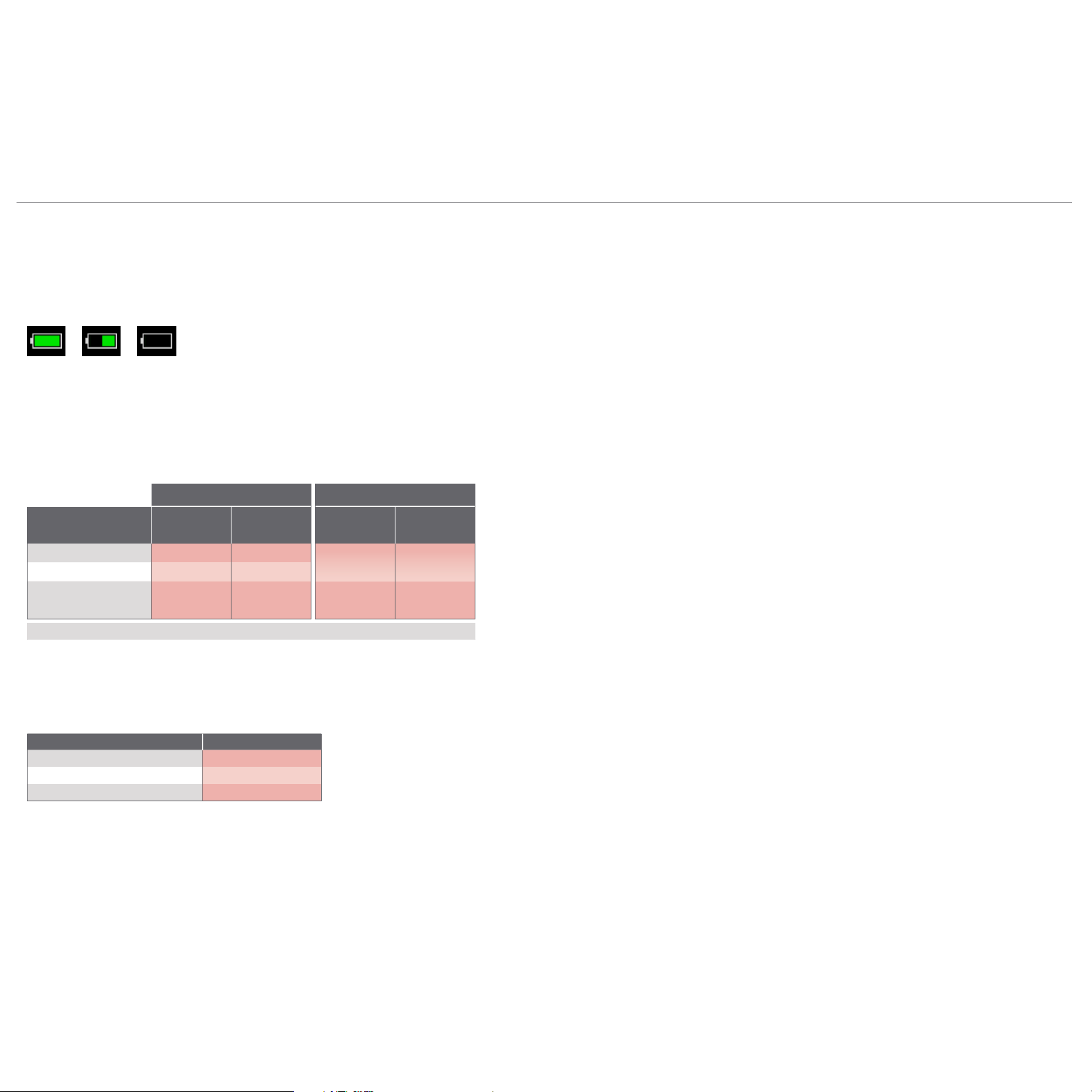
X
Power Icon States
The HPC50 battery icon indicates how much battery life is remaining.
100% 50% 0%
X
Battery Power
The HPC50 uses three(3) size AA (LR6) alkaline batteries.
Note: If the batteries discharge too deeply, the calibrator will automatically shut down to avoid battery leakage and false measurements.
Approved Batteries
CSA ATEX & IECEx
Specications 27
Approved
Battery Type
Rayovac Max Plus 815 T3 -20 to 50° C
Energizer E91* T4 -20 to 40° C
Duracell MN1500
Energizer EN91*
Replace batteries with approved type in non-hazardous locations only.
Energizer is manufactured by Energizer Holdings, Inc., and the Eveready Battery Company, Inc.
*
X
Battery Life
Temperature
Class
T3 -20 to 40° C T3 -20 to 50° C
Ambient
Temperature
Temperature
Class
T4 -20 to 50° C
Ambient
Temperature
Depending on how the HPC50 is congured, the battery life may dier. All numbers in the table below are without the use of the backlight, which will de-
crease the battery life.
Conguration Battery Life, In Hours
HPC50 with no external modules 35
HPC50 with one external module 25
HPC50 with two external modules 12
X
Battery Replacement
The HPC50 uses three AA batteries. Unscrew the four athead screws to gain access to the battery compartment. Replace the batteries taking care to note po-
larity for their proper installation. Failure to properly seal the battery compartment may allow water damage that could permanently compromise the HPC50.
Find Quality Products Online at: sales@GlobalTestSupply.com
www.GlobalTestSupply.com

HPC50 Series Operation Manual
RANGES AND RESOLUTIONS
psi bar kPa/MPa Overpressure psi kg/cm2 inHg inH20 mmHg mmH20 kPa bar mbar MPa
15PSI
30PSI
100PSI
300PSI
1KPSI
3KPSI
10KPSI
3.0 x 0.0001 0.00001 0.001 0.01 0.01 0 .1 0.001 0.00001 0.01
1BAR
3.0 x 0.001 0.0001 0.001 0.01 0.01 1 0.01 0.0001 0.1 0.00001
3BAR
10BAR
2.0 x 0.01 0.001 0.01 0 .1 0.1
30BAR
100BAR
1. 5 x 0.1 0.01 0.1
300BAR
1. 5 x 0.1 0.01
700BAR
3.0 x
100KPA 3.0 x
3.0 x
30 0KPA 3.0 x
2.0 x 0.001 0.0001 0.01 0 .1 0.1 1 0.01 0.0001 0.1 0.00001
2.0 x
1MPA 2.0 x
2.0 x
3MPA 2.0 x
2.0 x 0.01 0.001 0.1
2.0 x
10M PA 2.0 x
1. 5 x
30MPA 1. 5 x
1. 5 x
70MPA 1. 5 x
0.0001 0.00001 0.001 0.01 0.01 0 .1
0.0 01 0.0001 0.001 0.01 0.01 1
0.0 01 0.0001 0.01 0 .1 0.1 1
0.01 0.001 0.01 0.1 0.1
0.1 0.001 0.1
0.1 0.01 0.1
0.1 0.01
0.1 0.001 0.0001
1 0.01 0.0 01
1 0.01 0.001
0.1 0.001 1 0.0001
0.0 01 0.00001 0.01
0.0 01 0.00001 0.01
0.01 0.0001 0.1 0.00001
0.01 0.0001 0.1 0.00001
0.01 0.0001 0.1 0.00001
0.01 0.0001 0.1 0.00001
0.1 0.001 1 0.0001
0.1 0.001 1 0.0001
0.1 0.001
0.1 0.001
1 0.01
1 0.01
1 0.01
1 0.01
Specications 28
0.0001
0.0001
0.0 01
0.0 01
0.0 01
0.0 01
Resolutions shown are the maximum resolutions available. The resolution of your Crystal device may be dierent.
* CPF adaptor tting is not included. 1/4" medium pressure tube system is compatible with HIP LM4 and LF4 Series, Autoclave Engr SF250CX Male
and Female Series. See our CPF data sheet for additional adapter ttings.
X
Ordering Information
Number
of Sensors
HPC51 ...(Single)
HPC52
....(Dual)
1st Pressure
—
Range P/N
2nd Pressure
/
Range P/N
—
No .... (omit)
Yes ... -BARO
BARO
Option
—
Adapter
1/4 NPT
G 1/4 B
M20x1.5
SAMPLE PART NUMBERS
HPC51-1KPSI ..............................Single Sensor (1000 psi) HPC50 with a 1/4" male NPT pressure tting.
HPC52-3BAR-700BAR-BSP-BARO .....Dual Sensor (3 bar/700 bar) HPC50 with a 1/4" male BSP pressure tting
....(omit)
.....-BSP
...-M20
and BARO option.
Find Quality Products Online at: sales@GlobalTestSupply.com
www.GlobalTestSupply.com

HPC50 Series Operation Manual
Safety & Certifications
ATEX
HAZARDOUS LOCATIONS
Every HPC50 Series calibrator includes the following Intrinsic Safety approvals:
Safety & Certications 29
Ex ia IIC T4/T3 Ga
FTZU 18 ATEX 0043X
Ex ia IIC T4/T3 Ga
IECEx FTZU 18.0012X
Entity Parameters
mA/V port APMi/ATMi ports
Ui = 28 V Uo = 4.95 V
li = 94 mA lo = 731 mA
Pi = 654 mW Po = 880 mW
Ci = 3 nF Ci = 83.5 µF
Li = 0 Li = 32.2 µH
Co = 9.2 µF
Lo = 12 µH
WARNINGS: The following warnings apply to the HPC50 Series:
!
Do not use the USB connector in hazardous locations.
•
Replace batteries in non-hazardous locations and with approved types only.
•
Do not mix battery types or manufacturers.
•
T4 or T3 Temperature Class is based on selection of approved battery. See Approved Batteries.
•
Special conditions for safe use:
•
The equipment shall not be installed in a location where external conditions are conducive to the buildup of electrostatic charge.
Exia Intrinsically Safe and Non-Incendive for Hazardous Locations:
Class I, Division 1, Groups A, B, C, and D; Temperature Code T4/T3. Class I, Zone 0, AEx ia IIC T4/T3 Ga.
Sécurité in
Classe I, Division 1, Groupes A, B, C, and D; Code de température T4/T3. Classe I, Zone 0, AEx ia IIC T4/T3 Ga.
trinsèque et non incendiaire pour dangereux Lieux:
CERTIFICATIONS
The HPC50 Series has been tested and certied to comply with a variety of international standards.
This HPC50 complies with the Australian Radiocommunications (Electromagnetic Compatibility) Standard 2008.
Crystal Engineering declares that the HPC50 is in accordance with the ATEX Directive, the Electromagnetic Com-
patibility Directive, and the Pressure Equipment Directive per our declaration(s).
Find Quality Products Online at: sales@GlobalTestSupply.com
www.GlobalTestSupply.com
This HPC50 is approved for use as a portable test instrument for Marine
use and complies with DNV GL Rules for Classication of Ships, High
Speed & Light Craft, and Oshore Units.

HPC50 Series Operation Manual
MULTILANGUAGE SAFETY INSTRUCTIONS
English (English)
If the equipment is used in a manner not specied by the manufacturer, the protection provided by the equipment may be impaired.
X
Safety Instructions for Hazardous Locations
Do not use the USB connector in a hazardous location.
•
Replace batteries in non-hazardous locations, with approved batteries, only. Do not mix battery types or manufacturers.
•
It is the users responsibility to understand the proper application of this product in potentially explosive atmospheres.
•
Safety & Certications 30
X
Approved Batteries
Approved
Battery Type
Rayovac Max Plus 815 T3 -20 to 50° C
Energizer E91 T4 -20 to 40° C
Duracell MN1500
Energizer EN91
Replace batteries with approved type in non-hazardous locations only.
X
Special Conditions for Safe Use
The equipment must not be installed in a location where external conditions are conducive to electrostatic charge build-up.
Temperature
Class
CSA ATEX & IECEx
Ambient
Temperature
T3 -20 to 40° C T3 -20 to 50° C
Temperature
Class
T4 -20 to 50° C
Ambient
Temperature
Français (French)
Si l’équipement est utilisé d’une manière non spéciée par le fabricant, la protection fournie par l’équipement peut être altérée.
X
Instructions de sécurité pour les Zones Dangereuses
Ne pas utilisez le connecteur USB dans une Zone Dangereuse.
•
Remplacez les piles dans des Zones non-dangereuses, avec les piles appropriées, uniquement. Ne mélangez pas les types de piles ni les fabricants.
•
Il est de la responsabilité de l’utilisateur de bien comprendre l’application appropriée de ce produit en atmosphères explosives.
•
X
Piles Approuvées
Type de
Pile Approuvé
Rayovac Max Plus 815 T3 -20 to 50° C
Energizer E91 T4 -20 to 40° C
Duracell MN1500
Energizer EN91
La classe de température T4 ou T3 est basée sur la sélection de la pile approuvée.
Classement
Température
CSA ATEX & IECEx
Température
Ambiante
T3 -20 to 40° C T3 -20 to 50° C
Classement
Température
T4 -20 to 50° C
Température
Ambiante
X
Conditions spéciales pour une utilisation en toute sécurité
L’équipement ne doit pas être installé dans un endroit où les conditions extérieures sont propices à l’accumulation de charge électrostatique.
Find Quality Products Online at: sales@GlobalTestSupply.com
www.GlobalTestSupply.com

HPC50 Series Operation Manual
Support
TROUBLESHOOTING
The HPC50 Series is a very high performance calibrator. Due to the high resolution of this product, you may observe conditions that appear to be defects in the
product, but are in fact a result of being able to read and measure pressure to a degree not possible with other instruments.
Noisy or unstable reading when used with uids
When calibrating or comparing the indicated pressure from an
appear unstable—the least signicant digit jumps up and down several counts.
X
Reason
Gas (usually air) is trapped in the line between the
the combination of gas and uid is acting like a spring. At higher pressures (above 2000 psi, typically) this may eventually diminish, as the gas dissolves into
the uid.
X
Solution
Evacuate all tubing with a vacuum pump before introducing uid into the system.
HPC50
Non-repeatability of pressure measurements
When checking the calibrator against a hydraulic deadweight, increasing pressure measurements do not match decreasing pressure measurements.
X
Reason
As in the previous note, gas has dissolved into the hydraulic uid. When decreasing the pressure, the dissolved gas then leaves the uid, but at an uneven rate,
so a small pressure dierential (due to uid head pressure) may exist between the reference deadweight and the gauge being tested.
X
Solution
Evacuate all tubing with a vacuum pump before introducing uid into the system.
HPC50
against a hydraulic deadweight tester or piston gauge, the reading on the
and the deadweight tester. What is actually happening is the mass is oscillating up and down, and
HPC50
may
Support 31
Slow return to zero and/or non-repeatability of pressure measurements
X
Reason
Pressure port is obstructed.
X
Solution
Clean with low pressure uid. Do not touch diaphragm as damage will result.
Find Quality Products Online at: sales@GlobalTestSupply.com
www.GlobalTestSupply.com

HPC50 Series Operation Manual
CALIBRATION
If adjustment is required, we recommend returning the HPC50 to the factory. Factory service oers benets you won’t nd anywhere else. Factory calibra-
tion tests your HPC50 at a variety of temperatures utilizing NIST traceable standards, resulting in calibration certicates that provide performance data over
temperatur
an accreditation body by the International Laboratory Accreditation Cooperation, ILAC. Furthermore, upgrades may be available to add or enhance operating
features. We designed the product to last, and we support it so that you can get the most from your investment.
e. Our calibration facilities are A2LA accredited (cert #2601.01) to ISO 17025:2005 & ANSI/NCSL Z540-1-1994. A2LA is internationally recognized as
Support 32
Under normal operating conditions, we recommend the HPC50 be calibrated on an annual basis. Your quality system may require more or less frequent
calibration, or your experience with the gauge, or operating environment may suggest longer or shorter intervals.
Although we pref
with appropriate training and equipment. The following instructions are ONLY intended for such qualied personnel with appropriate test equipment. We
recommend that the calibration standards used have a minimum rated accuracy of 0.008% of reading, or equivalent in terms of percent of full scale. This level
of accuracy requires the use of piston (deadweight) gauges or very high performance pressure controllers.
the factory). As components age this may need to be changed to a value slightly higher or lower, to slightly increase or decrease all readings. This adjustment
can be made with a computer through CrystalControl.
er that you return the HPC50 to us for calibration, ordinary recertication and/or adjustments may be performed by any qualied personnel
There are no internal potentiometers. Each of the HPC50’s sensors has a “span factor” (userspan), set to approximately 1 (as shipped from
Calibration of P1 and P2
“Zero” the HPC50, then record displayed pressure for two or more pressure points. Determine if the HPC50 would benet from an overall
increase or decrease of the indicated pressures.
Adjust userspan accordingly and validate results.
Calibration for Barometric Reference Module (BARO)
The BARO module can be calibrated by selecting the Edit Calibration Data button while within the BARO Cong screen. Enter Userspan
and Oset information directly, or you can use the Calibration Wizard to calculate the optimum values for a 1 or 2 point calibration.
1 Remove the mounting bracket on the back of the HPC50, exposing the barometric sensor port.
2 Connect a exible 4.8 mm [3/16”] ID tubing from your clean pneumatic calibration reference to the BARO sensor.
You can also order the BARO calibration kit (P/N 4547), which includes the tubing.
CAUTION: Do not subject the BARO sensor to pressures less than 700 mbarA (10.153 PSIA), or greater than 1100 mbarA (15.954 PSIA), as this may
!
CAUTION: Direct contact with the surface of the BARO sensor may cause permanent damage. Direct sunlight on exposed BARO sensor may aect
!
cause permanent damage. Use only clean a clean dry pneumatic source.
readings slightly.
Find Quality Products Online at: sales@GlobalTestSupply.com
www.GlobalTestSupply.com

HPC50 Series Operation Manual
ACCESSORIES AND REPLACEMENT PARTS
P/N 104203 Test Lead Kit
Lead Kit, Red and black test leads with clips. (Included as standard)
P/N 6215 Protective Boot
Static dissipative protective boot. (Included as standard)
P/N 3951 Mini-USB Cable
The durable and high-speed Micro-USB cable enables data transfer in the most convenient form. (Included as standard)
P/N 3009 Hard Carrying Case
Aluminum carrying case with molded eggshell foam interior.
P/N 2888 Waterproof Carrying Case
Hard plastic carrying case with molded eggshell foam interior.
MPM-1/4MPT CPF Male to 1/4" Male NPT Fitting
(Included as standard)
MPM-1/4BSPM CPF Male to 1/4” Male BSP Fitting
(Included with -BSP)
MPM-M20x1.5M CPF Male to M20 Male Adapter
(Included with -M20)
Support 33
Find Quality Products Online at: sales@GlobalTestSupply.com
www.GlobalTestSupply.com
 Loading...