

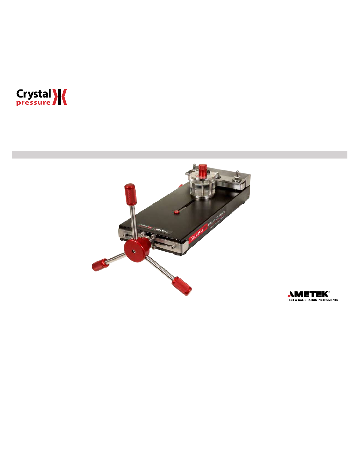
GaugeCalHP
Operation Manual
for GaugeCalHP and System G
Find Quality Products Online at: sales@GlobalTestSupply.com
www.GlobalTestSupply.com

Contents
Overview ............................................................. 1
Introduction .......................................................... 1
Features and Parts Lists ................................................ 2
Setup .................................................................. 4
Assembly ............................................................. 4
Mounting ............................................................. 5
Safety Instructions ................................................ 6
General Cautions . . . . . . . . . . . . . . . . . . . . . . . . . . . . . . . . . . . . . . . . . . . . . . . . . . . . . . 6
Operating Instructions ........................................... 7
Generating Pressure ................................................... 7
Operation ............................................................ 10
Connection Diagram ............................................. 13
GaugeCalHP to Crystal Reference Indicator ............................. 13
Specifications ...................................................... 14
Performance ......................................................... 14
Materials ............................................................. 14
Dimensions .......................................................... 14
Accessories ........................................................... 14
Shipping Information ................................................. 14
Support .............................................................. 15
Troubleshooting ...................................................... 15
Maintenance ......................................................... 15
Ordering Information, Spare Parts, and Fitting Kits ...................... 16
Contact Us ........................................................... 17
Factory Service ....................................................... 17
Warranty ............................................................. 17
Find Quality Products Online at: sales@GlobalTestSupply.com
www.GlobalTestSupply.com
GaugeCalHP Comparator Operation Manual
Overview
INTRODUCTION
Thank you for purchasing a GaugeCalHP™ Pressure Comparator from Crystal Engineering. The GaugeCalHP is a self-contained, precision hydraulic pressure
comparator intended for the calibration of pressure gauges rated up to 15
or oil.
Using this comparator for calibration is much faster than deadweight testers and most automated pressure controllers. The GaugeCalHP is so quick and easy
to use, it is ideal for calibrating those low cost gauges that are often overlooked for ISO9000 compliance.
In fact, you can calibrate most gauges, transmitters, pressure safety valves, sensors, and switches in less than ten minutes (5 to 10 test points, increasing and
decreasing pressure) using the methods described in this manual.
The GaugeCalHP hydraulic comparator may be ordered as part of a Pump System, complete with a Crystal Pressure Indicator. GaugeCalHP Pump Systems
include the most commonly used pressure ttings, seals, etc. All packaged in a carrying case with custom insert.
Spend a few minutes to read this manual and learn how you can get the most benet from your GaugeCalHP.
Note:
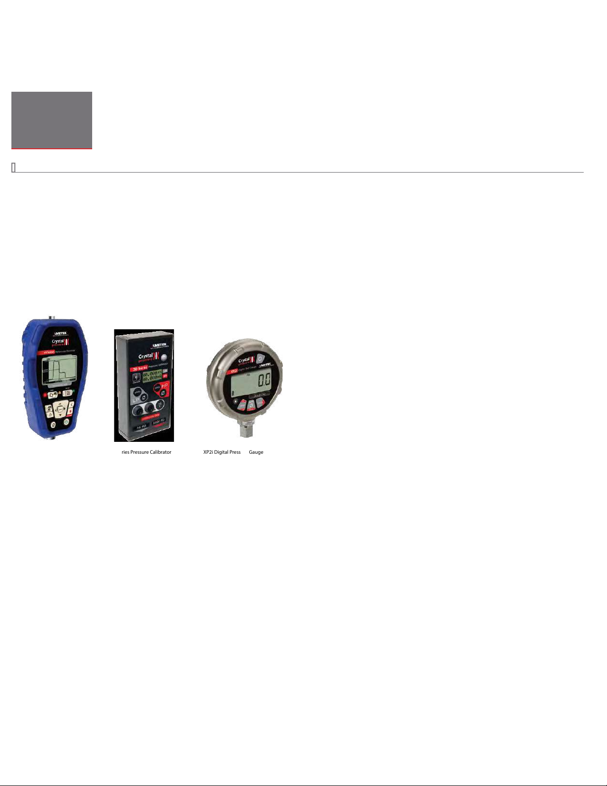
We recommend using one of the following indicators with the GaugeCalHP.
000 psi / 1000 bar / 100 MPa. You may ll the GaugeCalHP with your choice of water
Overview 1
nVision Reference Recorder 30 Series Pressure Calibrator XP2i Digital Pressure Gauge
Find Quality Products Online at: sales@GlobalTestSupply.com
www.GlobalTestSupply.com
GaugeCalHP Comparator Operation Manual
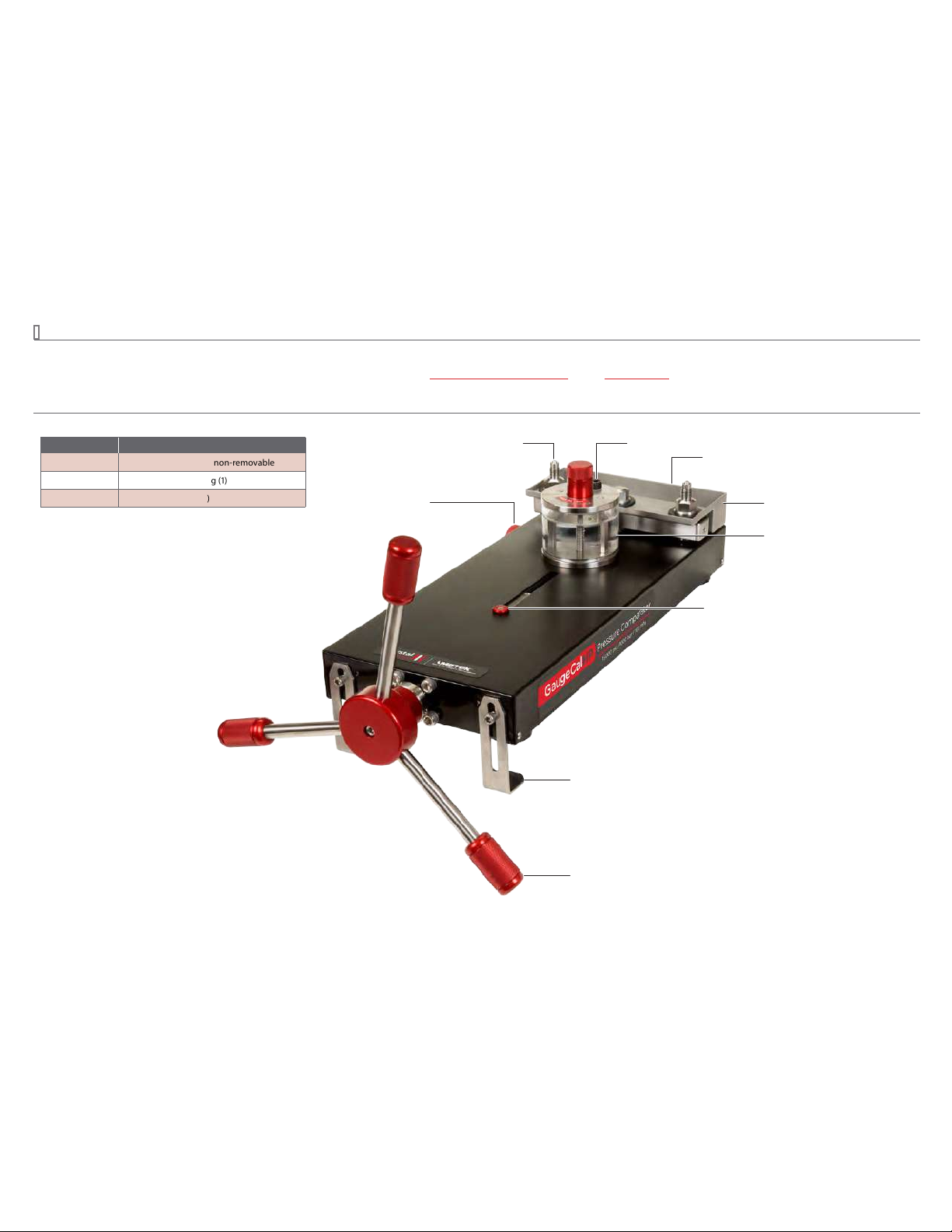
FEATURES AND PARTS LISTS
Each comparator includes a ne adjust for precise pressure adjustments. The reference indicator threads directly to the CPF Male tting.
The device under test connects to the supplied 1/4” Female NPT tting. For more sizes see the Connection Diagram on page 13 and the CPF Datasheet.
U.S. Patent No. 8,794,677
Parts Included with the GaugeCalHP
Part Number Description
— CPF Male Fittings (2)—non-removable
MP F15K-1/4 FPT 1/4" Female NPT Fitting (1)
5102 Fine Adjust (installed)
With easy alignment swivel capability.
Easy to use, even at 15000 psi.
Fine Adjust
Connection Fitting
Relief Valve
No Mess Drip Tray
Captures uid from bleeding the system.
Pivot Manifold
Manifold rotates for testing large size gauges.
Reservoir
Clear, removable reservoir with a ll line.
Travel Indicator
Shows the amount of stroke available.
Overview 2
Brackets
For easy mounting to a table top.
Removable Handle Assembly
For transport. Includes captive screw.
Find Quality Products Online at: sales@GlobalTestSupply.com
www.GlobalTestSupply.com

GaugeCalHP Comparator Operation Manual
Parts Included with Pump Systems
System G
GOX and GWX
Part Number Description
MP F15K-1/4 FPT CPF Female to 1/4" NPT Female Fitting
*
MPF-1/4BSPF
MPF-1/8MPT
MPF-CA P
60 R120 1/4” Bonded Seals
5102 Fine Adjust (installed)
1351 Test Leads; Red & Black, including clips
5249
60I10 4 Pack Tape (1 roll)
5101 Rolling Waterproof Carrying Case
*
These ttings are rated to 10 000 psi/100 bar.
**
The MPF-1/8MPT ttings and 1351 Test Leads are included only with Pump Systems for the 30 Series Calibrator.
CPF Female to 1/4" BSP Female Fitting
*
1/8” MPT Fitting (for 30 Serie s Calibrator)
*
CPF Female Cap Fitting
Protective Vinyl Cap
**
(GaugeCalHP)
**
(
2 )
(
2 )
(
5 )
(
4 )
Hydraulic Fluid
GaugeCalHP comparators are only available delivered empty. You will still need to specify what uid type you are going to use (for example; GOX for Oil or GWX for Water).
Ordering a Pump System
Any GaugeCalHP Pump System may be ordered with or without a reference indicator. The table below provides an explanation of the Pump System ordering
scheme when ordering a system without an indicator. For details on ordering the Pump Systems with an indicator, see the indicator datasheet.
X
Reference Indicator Reference Indicator Included Pump System Liquid
nVision ....NV No ...-NONE System G (GaugeCalHP–oil) ......-G OX Drained ...-E
30 Series
...IS30 System G (GaugeCalHP–water) ...-GWX
.......XP2i
XP2i
m1
.........M1
SAMPLE PART NUMBERS
NV-NONE-GOX-E .......System G pump system (for an nVision), drained of uid, for use with oil.
IS30-NONE-GWX-E ....System G pump system (for an nVision), drained of uid, for use with water.
15KPSIXP2i-GWX-E ...System G pump system, drained, for use with water, with a 15 000 psi XP2i
gauge included.
Overview 3
Find Quality Products Online at: sales@GlobalTestSupply.com
www.GlobalTestSupply.com

GaugeCalHP Comparator Operation Manual
Setup
ASSEMBLY
X
Install the Handle Assembly
Install the handle assembly by tightening the captive screw using the included wrench.
X
Install the No Mess Drip Tray
Press the no mess drip tray onto the pivot manifold.
Setup 4
Find Quality Products Online at: sales@GlobalTestSupply.com
www.GlobalTestSupply.com

GaugeCalHP Comparator Operation Manual
MOUNTING
The GaugeCalHP includes rubber feet that stabilize the unit up to 5000 psi. At pressures above 5000 psi, the force required to rotate the handle may cause the
base of the comparator to lift. One of two methods may be used to mount the GaugeCalHP to a bench or table.
X
Using the Mounting Brackets
1 Loosen the mounting bracket screws.
2
Rotate the brackets, then slide them over the front of your table (max thickness of 1.75”).
Tighten the mounting bracket screws.
3
Rotate the mounting brackets… then slide them over the front of your table.
Note: To ensure the comparator is mounted securely, grip and compress the brackets to the underside of the table while tightening the mounting screws.
X
Install Onto a Table
Order the optional Table Mount Kit (P/N 5191) to bolt to a table.
Setup 5
Find Quality Products Online at: sales@GlobalTestSupply.com
www.GlobalTestSupply.com

GaugeCalHP Comparator Operation Manual
Safety Instructions
Follow these instructions for safe and reliable operation of your GaugeCalHP Pressure Comparator.
GENERAL CAUTIONS
Avoid knocking, bumping or dropping the pressure system. This can cause permanent damage to the system and loss of accuracy.
•
The pressure system must not be used for any purposes other than those described in this manual and for any application other than precision pressure
•
calibration jobs.
The pressure system should only be used by TRAINED PERSONNEL.
•
None of our calibration systems are cleaned or prepared for OXYGEN SERVICE. DO NOT USE our systems for this purpose.
•
Do not disconnect any parts from the system when pressurized.
•
Do not connect any external pressure source to this system. This system is designed to test pressure measuring devices connected to the manifold only.
•
Pressure from an external source can result in explosion of the uid reservoir and possible personal injuries.
The pressure inside the pump can be extremely high. Ensure that all pressure connections have been established correctly.
•
Safety Instructions 6
Find Quality Products Online at: sales@GlobalTestSupply.com
www.GlobalTestSupply.com
GaugeCalHP Comparator Operation Manual
Operating Instructions
GENERATING PRESSURE
X
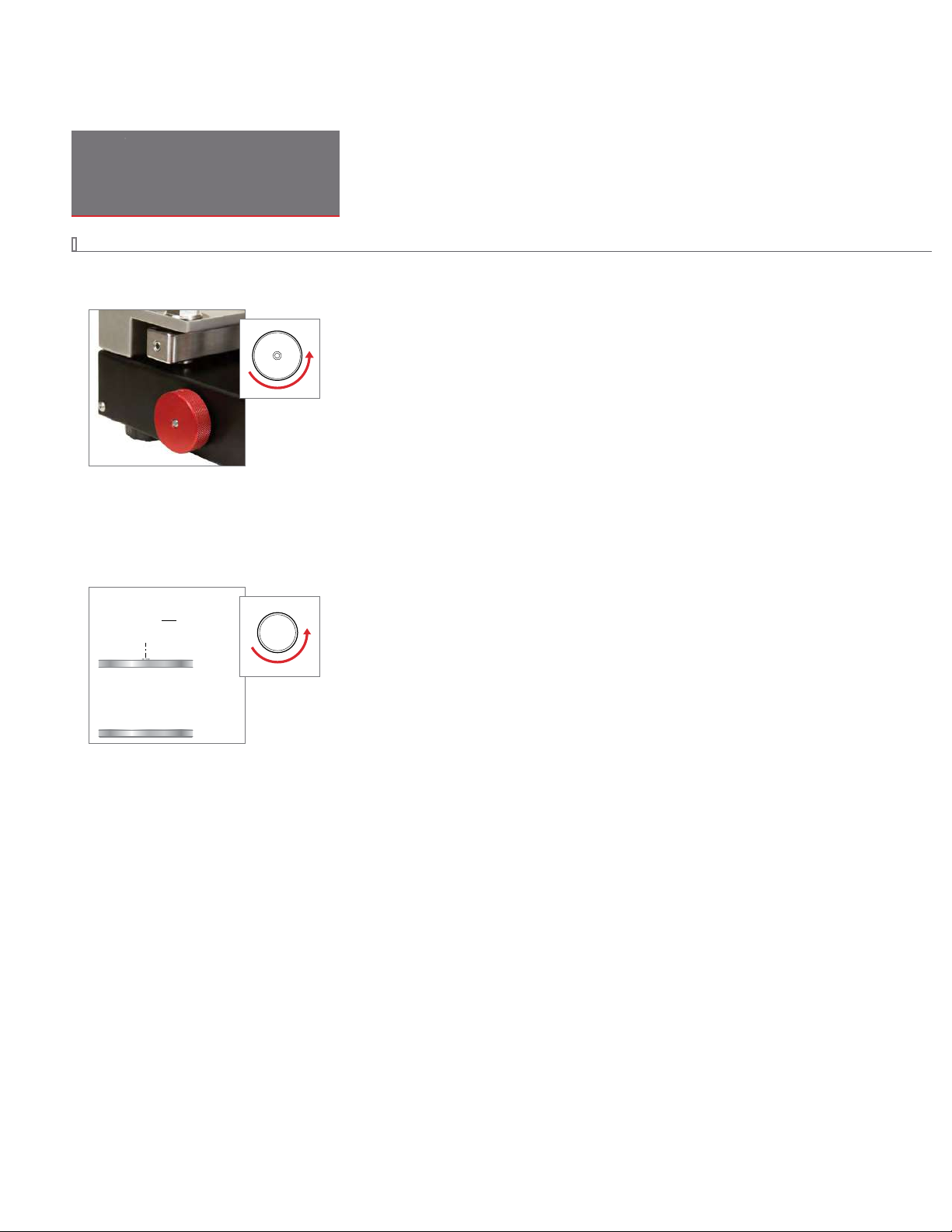
Prepare the Fine Adjust
Turn the ne adjust counter-clockwise about 10 rotations to provide room to increase or decrease pressure as needed.
X
Fill the Reservoir
The test uid can be either water or lightweight oil.
Note:
If using oil, we recommend AMETEK MGAAA oil.
Turn the handle fully counter-clockwise until it stops.
1
2
Turn the reservoir knob fully counter-clockwise and remove it from the reservoir.
Operating Instructions 7
Reservoir Knob
Find Quality Products Online at: sales@GlobalTestSupply.com
www.GlobalTestSupply.com

GaugeCalHP Comparator Operation Manual
3 Fill the reservoir to the ll line.
Fill Line
X
Bleed Air from the System
Tighten the reservoir knob clockwise until uid comes out of the ttings. The drip tray will collect the spilled uid.
X
Install the Device Under Test
Your GaugeCalHP comes with two CPF male ttings (non-removable) and an adapter to 1/4" Female NPT that is rated to 15 000 psi (P/N MPF15K-1/4FPT).
1
Connect the adapter to your device under test.
You will need to use thread tape or sealant to create a leak free seal.
2
Loosely tighten (3 turns only) the other end of the adapter to the connection manifold.
Note:
For additional sizes and pressure ratings, see the Connection Diagram on page 13.
For applications up to 10
000 psi, create nger-tight, leak-free seals by using CPF ttings. Visit the website for more information on CPF.
Operating Instructions 8
Note:
If you are using CPF quick test ttings, do not use thread tape.
CAUTION: Never use a wrench to tighten quick test ttings.
!
Finger-tight seal u ses a
Viton 90 o-ring for a seal up to
10 000 psi/ 700 bar/ 70MPa
(-20 to 50C)
point of contac t
Wrench-tight creates a
metal/metal seal up to
10 000 psi/ 700 bar/ 70MPa
(-40 to 150C)
Find Quality Products Online at: sales@GlobalTestSupply.com
www.GlobalTestSupply.com

GaugeCalHP Comparator Operation Manual
X
Install the Reference Indicator
1 Loosely tighten (3 turns only) the reference to the connection manifold.
Note:
If the reference will not t because you have a large device under test, turn the pivoting manifold to create extra space.
Shown with a Quick Test Fitting (not included).
2 Bleed the system of remaining air by turning the reservoir knob clockwise until uid drips out of the CPF weep hole on the base of the reference and on the
connection tting.
Operating Instructions 9
Turn the reservoir knob… until uid drips from the CPF weep hole.
Find Quality Products Online at: sales@GlobalTestSupply.com
www.GlobalTestSupply.com

GaugeCalHP Comparator Operation Manual
3 Tighten the reference and the device under test. The connection only needs to be nger tight for a seal to 15 000 psi.
4
If necessary, continue to turn the devices clockwise until they are in the desired position.
Note:
If necessary, ll the uid in the reservoir back up to the ll line.
OPERATION
X
Perform a Calibration
1 Vent the system by turning the reservoir knob counter-clockwise until a gap is visible between the reservoir knob and the lid.
Gap
Operating Instructions 10
2
Turn on the reference indicator, and then select the pressure units required for the gauge to be tested.
For detailed operating instructions, refer to the documentation you received with your reference.
Find Quality Products Online at: sales@GlobalTestSupply.com
www.GlobalTestSupply.com

GaugeCalHP Comparator Operation Manual
3 Press the (zero) button on your reference.
We recommend that you exercise the device under test by applying the full scale pressure one or more times.
4
To apply pressure… Turn the handle in a clockwise direction.
To decrease pressure… Turn the handle in a counter-clockwise direction.
5
After decreasing the pressure to zero, recheck the uid level in the reservoir and rezero the reference, if necessary. You will notice that the application of
pressure is non-linear, therefore pressure increases at a more rapid rate at higher pressures.
6 Turn the handle clockwise until the approximate pressure is obtained.
Allow time for the adiabatic eect to stabilize.
7
8
Use the ne adjust knob to obtain the exact pressure.
9 Compare the pressure on the device under test to the pressure displayed on the reference, and record the reading.
Operating Instructions 11
Checking the accuracy of an analog pressure gauge against the display of the reference.
Find Quality Products Online at: sales@GlobalTestSupply.com
www.GlobalTestSupply.com

GaugeCalHP Comparator Operation Manual
X
Perform a Quick Test Calibration
An alternative method eliminates the time required to wait for thermal pressure stability. This method works with the Crystal XP2i and nVision, but not with
the 30 Series.
1
Set the reference to detect peaks and clear any stored peak value.
Slowly increase pressure to the rst major graduation on the device under test (or to the rst calibration point).
2
Increase pressure slowly, so that you don’t overshoot the mark (or point).
The maximum pressure displayed on the reference will be the pressure that was applied—even if actual pressure drops again immediately.
Record the peak reading and continue to the next test point or mark.
3
If you are also checking the gauge for hysteresis, the procedure is the same, except that you start at full scale and set the reference for the peak low. Elimi
nating the time required to wait for thermal equilibrium, signicantly shortens the amount of time it takes to calibrate a gauge.
To automatically collect the readings directly from the reference, use FastCalXP calibration software.
Note:
X
To vent the system
Turn the handle counter-clockwise until it stops.
Vacuum Use
X
To Generate Vacuum
1 Loosen the reference indicator about 3 turns counter-clockwise.
2
Turn the handle clockwise and verify that uid is dripping out of the CPF weep hole into the drip tray. Continue to turn the handle until it stops.
3
Tighten the reference.
4
Rotate the handle counter-clockwise to generate a vacuum.
You can generate up to -12.5 psi.
Be aware that the system will vent during the last inch of travel.
Note:
Operating Instructions 12
-
Find Quality Products Online at: sales@GlobalTestSupply.com
www.GlobalTestSupply.com

GaugeCalHP Comparator Operation Manual
Connection Diagram
GAUGECALHP TO CRYSTAL REFERENCE INDICATOR
Connection Diagram 13
XP2i
Digital Test Gauge
Hi
peak
Lo
Pressure Calibrator
Reference Recorder
nVision
Intrinsically Safe
3000 PSI
zero
units
clear
30 Series
10
MPF-1/8MPT
*
MPF 15K-1/4F PT
*
CPF Male Fittings (2)
Intrinsically Safe
15
Thread tape
required here.
NPT MALE
NPT FEMALE
BSP
TRANSMITTER
TUBE
CPF
ADDITIONAL
MPF-1/8QTM 1/8" Quick Test NPT Male
MPF-1/8MPT 1/8" NPT Male
MPF-1/4QTM 1/4" Quick Test NPT Male
MPF-1/4MPT
Additional NPT si zes available in non-CPF MP a dapters
MPF-1/8QTF 1/8" Quick Test NPT Female
MPF-1/4QTF 1/4" Quick Test NPT Female
MPF-1/4FPT 1/4" NPT Female
MPF-1/2QTF 1/2" Quick Test NPT Female
Additional NPT si zes available in non-CPF MP a dapters
MPF-1/8BSPF G 1/8" Female
MPF-1/4BSPF G 1/4" Female
MPF-3/8BSPF G 3/8" Female
MPF-1/2BSPF G 1/2" Female
MPF-5/16TRM for Foxboro, Rosem ount, & Yokogawa
MPF-1/4TRM for Ho neywell
MPF-1/4TBM 1/4" Tube Male
MPF-3/8TBM 3/8" Tube Male
MPF-1/2TBM 1/2" Tube Male
MPF-MPF Female to Female
MPF-MPFTU T-Union (Female)
MPF-MPFBULK Bulkhead (Female to Female)
MPF-CAP Cap
MPF-M20QTF M20 x 1.5 Quick Test Female
MPF-M20X1.5F M20 x 1.5 Female
MPF-QCN Quick-Connect Nut
MPF-AN4M AN4 Male
1/4" NPT Male
10
10
10
10
10
10
10
5
10
10
10
10
5
5
5
10
10
10
10
5
10
5
5
Medium Pressure FEMALE to NPT FEMALE
Medium Pressure FEMALE to NPT MALE
Medium Pressure MALE to NPT FEMALE
Medium Pressure MALE to NPT MALE
5
5
5
300 bar/5000 psi
10
700 bar/10 000 psi
15
1000 bar/15000 psi
(Non-CPF MP ttings require wrench tightening.)
4501 1/8 NPT
4715 1/4 NPT
4502 3/8 NPT
4503
4714 1/4 NPT
4494 3/8 NPT
4495 1/2 NPT
4496 3/4 NPT
4497 1/8 NPT
4498 1/4 NPT
4499 3/8 NPT
4500 1/2 NPT
4698 1/4 NPT
4492 3/8 NPT
4493 1/2 NPT
1/2 NPT
15
15
15
15
15
15
15
10
15
15
15
15
15
15
15
* These parts are includ ed with the pump. All other pa rts are supplied as p art of a pump system, or m ay be ordered separate ly. All BSP connections requ ire bonded seals.
CPF Fittings Non-CPF MP Fittings
Find Quality Products Online at: sales@GlobalTestSupply.com
www.GlobalTestSupply.com

GaugeCalHP Comparator Operation Manual
Specifications
Specications 14
PERFORMANCE
Hydraulic Pressure
Maximum . . . . . . . . . . . . . . . . . . . . . . . 15 000 psi / 1000 bar
Vacuum
. . . . . . . . . . . . . . . . . . . . . . . . . -12.5 psi / -0.86 bar / -86.2 kPa
Pneumatic Pressure
Maximum . . . . . . . . . . . . . . . . . . . . . . . 400 inH2O / 995 mbar
Sensitivity (ne adjust)
. . . . . . . . . . . 0.01 inH2O / 0.025 mbar
Burst Pressure
Pressure . . . . . . . . . . . . . . . . . . . . . . . . .>25 000 psi / 1700 bar
MATERIALS
Wetted Materials. . . . . . . . . . . . . . . . .Stainless Steel plus Seals and Acrylic Reser voir
Enclosure
. . . . . . . . . . . . . . . . . . . . . . . . Anodized Aluminum
Seals
. . . . . . . . . . . . . . . . . . . . . . . . . . . . Buna N (Nitrile), Viton, and Urethane
. . . . . . . . . . . . . . . . . . . . . . . Water, Oil, or Air
Test Media
DIMENSIONS
Width . . . . . . . . . . . . . . . . . . . . . . . . . . . 8.3 in / 210 mm
Length
. . . . . . . . . . . . . . . . . . . . . . . . . . 20.50 in / 520 mm
Height (base)
Height (with handles)
Weight
Piston Stroke Volume
Reservoir Volume . . . . . . . . . . . . . . . .10.8 in3 / 176.9 cm
ACCESSORIES
. . . . . . . . . . . . . . . . . . . . 5.5 in / 140 mm
. . . . . . . . . . . .11 in / 280 mm
. . . . . . . . . . . . . . . . . . . . . . . . . . 20 lbs / 9 kg
. . . . . . . . . . . . 0.8 in
3
/ 13.1 cm
3
3
Included
Adapter . . . . . . . . . . . . . . . . . . . . . . . . . 1/4” Female NPT (P/N MPF15K-1/4FPT)
SHIPPING INFORMATION
Shipping Weight . . . . . . . . . . . . . . . . . 22 lbs / 9.9 kg
Dimensions
. . . . . . . . . . . . . . . . . . . . . .24 in x 12 in x 12 in /
610 mm x 305 mm x 305 mm
Find Quality Products Online at: sales@GlobalTestSupply.com
www.GlobalTestSupply.com

GaugeCalHP Comparator Operation Manual
Support
TROUBLESHOOTING
Unstable Pressure
X
Problem: Pressure cannot be generated correctly, or set pressure does not remain stable.
X
Solutions:
• Check that all adapters and pressure ttings have been tightened suciently to eliminate leaks.
• Conrm test uid does not contain air (air in the uid can increase adiabatic eects). You may have to adjust the pressure a few times before the
pressure is stable enough for calibration.
• Adiabatic and thermodynamic eects may be aecting the pressure reading. High pressure hydraulic systems are sensitive to temperature and move-
This eect will disappear after a period of time.
ments.
If the pressure is still not stabilizing, the system may be in need of service. Please contact your local distributor for advice.
Note: Always readjust the pressure after 5 to 10 minutes to allow time for settling of above eects.
MAINTENANCE
Users should/must carry out the following cleaning procedures when required:
Standard exterior cleaning
Heavily soiled cleaning
Reservoir
. . . . . . . . . . . . . . . . . . . . . . . . Can be removed for easy cleaning. Turn the GaugeCalHP onto its side and loosen the two screws holding the reservoir in
To clean the clear acrylic reservoir tube use a soft cloth or soap and water only. Never use chemical cleaners.
. . . . . . . Clean using a soft, damp cloth.
. . . . . . . . . . . The instrument may also be cleaned using isopropyl alcohol when heavily soiled.
place. Slide the screws through the hole and quickly remove the reservoir as uid may leak out of the bottom.
Replace test uid if necessary.
Support 15
Find Quality Products Online at: sales@GlobalTestSupply.com
www.GlobalTestSupply.com

GaugeCalHP Comparator Operation Manual
ORDERING INFORMATION, SPARE PARTS, AND FITTING KITS
Ordering Information
P/N GAUGECALHP GaugeCalHP Pressure Comparator
Pressure Comparator, two CPF male ttings (installed), and one 1/4" FNPT adapter (P/N MPF15K-1/4FPT )
.
Spare Parts
P/N 5102 Fine Adjust (included)
P/N 5101 Rolling Case
Two MPF-CAP ttings to prevent leaks while in transit, two hold-down straps, and uid bottle
P/N FASTCALXP Gauge and Transmitter Calibration Software
FastCalXP software, USB Security Key, CD, and USB-RS232 adapter
P/N 3327 USB Footswitch for FastCalXP
P/N 5191 Mounting Kit
P/N 5103 Rebuild Kit
.
.
Fitting Kits
P/N 4013 Quick Test NPT Kit—A set of CPF conversion ttings for connecting to 1/8", 1/4", and 1/2" male NPT; without tools or thread tape.
Finger-tight to working pressure up to 10
Includes (1) MPF-1/8QTF, (1) MPF-1/4QTF, and (1) MPF-1/2QTF CPF tting
P/N 4015 BSP Test Kit—CPF conversion ttings to connect to male BSP: G 1/8, G 1/4, G 3/8, and G 1/2. Working pressure up to 10 000 psi / 700 bar.
Includes (1) MPF-1/8BSPF, (1) MPF-1/4BSPF, (1) MPF-3/8BSPF, and (1) MPF-1/2BSPF CPF tting
000 psi / 700 bar.
.
.
Support 16
Test Fluid
X
Recommended Oil
P/N: MGAAA/QT ...Hydraulic Oil. Quart.
P/N: MGAAA/GL
...Hydraulic Oil. Gallon.
Find Quality Products Online at: sales@GlobalTestSupply.com
www.GlobalTestSupply.com

GaugeCalHP Comparator Operation Manual
CONTACT US
FACTORY SERVICE
Please complete the Return Material Authorization (RMA) form to generate an authorization number and provide return instructions.
WARRANTY
Crystal Engineering Corporation warrants the GaugeCalHP Comparator to be free from defects in material and workmanship under normal use and service for
one (1) year from date of purchase to the original purchaser. It does not apply to batteries or when the product has been misused, altered or damaged by ac-
cident or abnormal conditions of operation.
rystal Engineering will, at our option, repair or replace the defective device free of charge and the device will be returned, transportation prepaid. However, if
C
we determine the failure was caused by misuse, alteration, accident or abnormal condition of operation, you will be billed for the repair.
CRYSTAL ENGINEERING CORPORATION MAKES NO WARRANTY OTHER THAN THE LIMITED WARRANTY STATED ABOVE. ALL WARRANTIES, INCLUDING IMPLIED
WARRANTIES OF MERCHANTABILITY OR FITNESS FOR ANY PARTICULAR PURPOSE, ARE LIMITED TO A PERIOD OF ONE (1) YEAR FROM THE DATE OF PURCHASE.
CRYSTAL ENGINEERING SHALL NOT BE LIABLE FOR ANY SPECIAL, INCIDENTAL OR CONSEQUENTIAL DAMAGES, WHETHER IN CONTRACT, TORT OR OTHERWISE.
Note:
(USA only) Some states do not allow limitations of implied warranties or the exclusion of incidental or consequential damages, so the above limita-
tions or exclusions may not apply to you. This warranty gives you specic legal rights and you may have other rights which vary from state to state.
Support 17
Find Quality Products Online at: sales@GlobalTestSupply.com
www.GlobalTestSupply.com

Find Quality Products Online at: sales@GlobalTestSupply.com
www.GlobalTestSupply.com
 Loading...