

Page 1
SUMMIT
Bottled Water Dispenser User Manual
Page 2
1
2
3
4
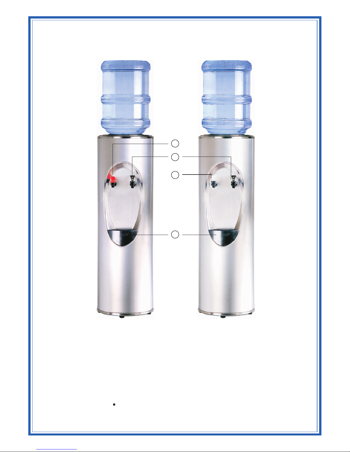
1. Hot Water Faucet (with Child Safety Feature)
2. Cold Water Faucet
3. Cook Water Faucet (Room Temperature Water)
4. Drip Tray
Parts may not appear exactly as shown
Page 3
THANK YOU FOR BUYING A CRYSTAL MOUNTAIN WATER COOLER!
RECEIVING
Inspect the cooler box immediately and carefully for any evidence of shipping or handing
damage before signing to receive goods. In case of shipping damage, claims should be filed
immediately with the carrier. Please note that the carrier will not accept claims for any
damage discovered after the signing for UNINSPECTED GOODS. Ensure cooler stands
upright for 24 hours before plugging it in.
Note: Remove the Protective plastic coating from the surface of the Stainless Steel body
prior to use.
OPERATION
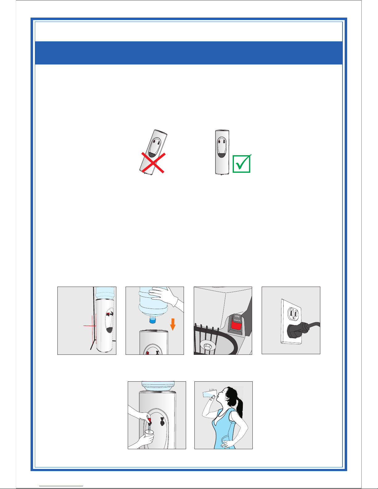
1. Place the water cooler on a flat level surface in a cool shaded location near a grounded
wall outlet. Position water dispenser so that the back of the unit is a minimum of 2 inches /
5cm away from the wall to ensure proper ventilation (Figure 1).
2. Place the water bottle on top of the cooler appropriately (Figure 2). For open reservoir
models, the bottle cap needs to be removed.
3. Ensure that the available power supply matches the cooler’s voltage specifications
indicated on the nameplate label (located at the rear). Plug power supply cord into
receptacle (Figure 4). Please ensure that cooler is set up so as access to the power outlet
and plug is unobstructed.
4. Do not draw water from the cooler for about 30 minutes to let the water cool or heat.
Optimum water temperatures will be reached after several hours of operation (Figure 5
and Figure 6).
Note: On H&C models, vent the hot tank by holding the red faucet open until water flows
out (Figure 3). (Heater switch may now be turned on)
Note: To provide additional protection from the risk of shock, this unit MUST be
connected to a ground fault circuit interrupter (GFCI) outlet at all times. Use of an
extension cord will void any warranties.
Figure 1
Figure 2 Figure 4
Figure 5 Figure 6
Figure 3
2 inches (5 cm)
Page 4
5. Ensure the following when cooler is to be serviced:
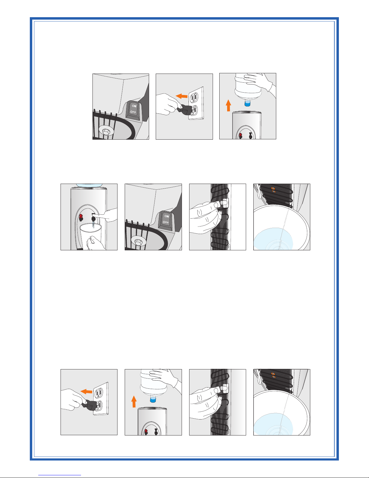
5.1 Turn off Hot Tank Switch (Figure 7) (Hot & Cold models only) and disconnect power
supply cord (Figure 8).
5.2 Remove bottle from reservoir. (Figure 9)
5.3 Use a bucket to drain water from the cold water reservoir through faucets (Figure 10).
On Hot & Cold models (Figure 11), turn off hot tank switch as above. Allow 1 hour for
the hot water to cool down inside the hot water tank. R emove the drain plug at the rear of
the cooler to drain into a container (Figure 12 and Figure 13).
REMOVABLE RESERVOIR
E & S Series
On Cook & Cold and Hot & Cold models the reservoir can be removed easily by following the
steps given below.
1. Unplug (Figure 14) and approach the cooler from the front.
2. Remove the water bottle (Figure 15) and drain water from the reservoir and hot tank,
remembering to cool and drain hot tank. Allow 1 hour for hot water to cool down inside the
hot tank before removing the drain plug at the rear of the cooler to drain into a bucket
(Figure 16 and Figure 17).
CAUTION! ALWAYS DRAIN WATER COMPLETELY
BEFORE SHIPPING OR STORING TH E CO OLER!
Figure 7 Figure 8 Figure 9
Figure 10 Figure 11 Figure 12 Figure 13
Figure 14 Figure 15 Figure 16 Figure 17
Page 5
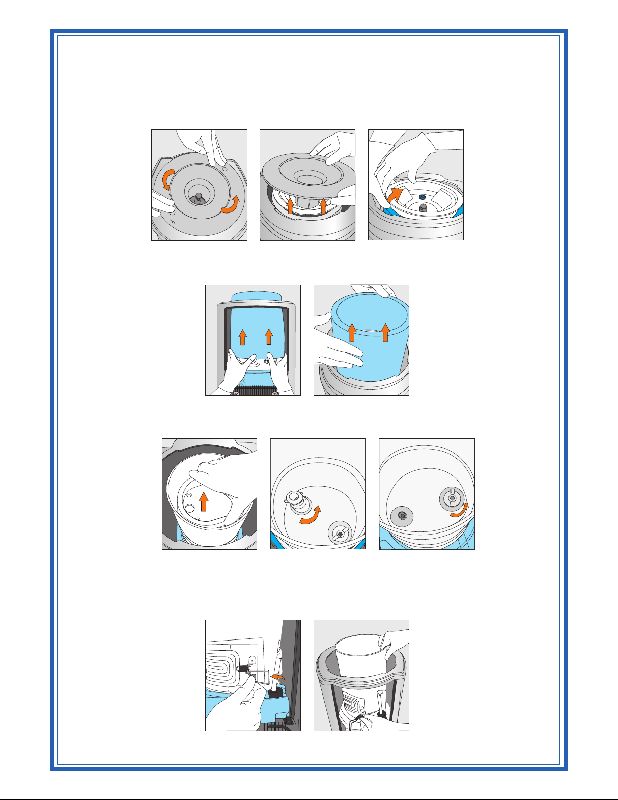
3. Use t he fingertips of both hands to press downward on the Cone and turn counter clockwise
till it is free from the cooler opening. (Figure 18 and Figure 19) then remove the
TM
DryGuard (Figure 20).
4. Use fingers of both hands to lift up and remove the insulation jacket covering the reservoir,
from the cooler opening (Figure 21 and Figure 22).
5. Remove the baffle cup by lifting straight out (Figure 23). Loosen & remove the baffle stem
and wing nut by turning counterclockwise (Figure 24 and Figure 25).
6. Approach the cooler from the rear and open the latch provided on the evaporator band
(Figure 26).
7. Use both hands to loosen the reservoir from the evaporator band and lift is straight though
the cooler opening (Figure 27).
TM TM
Note: the DryGuard lid is standard on the Summit cooler. See the DryGuard section for
installation and removal instructions.
Figure 18 Figure 19 Figure 20
Figure 22
Figure 23
Figure 24
Figure 26 Figure 27
Figure 21
Figure 25
O
P
EN
OP
EN
Page 6
R, P, & G Series
On Cook & Cold and Hot & Cold models the reservoir can be removed easily by following the steps
given below.
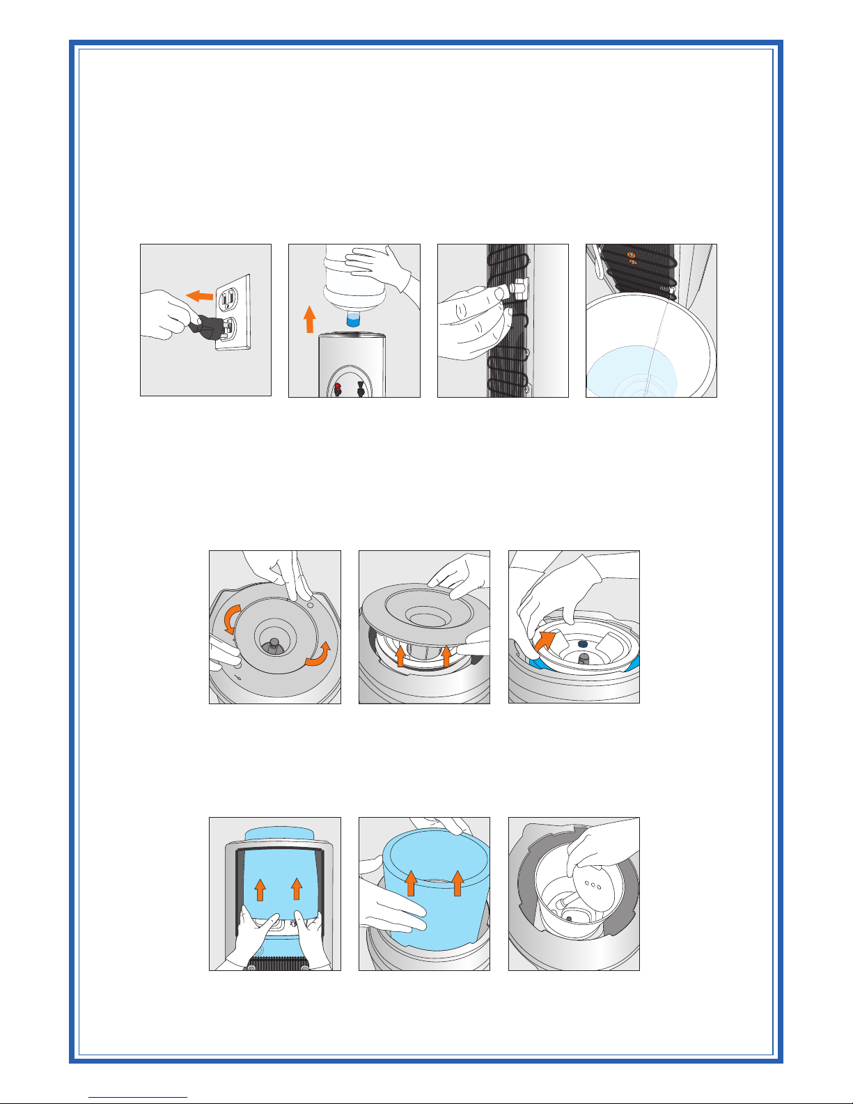
1. Unplug (Figure 28) and approach the cooler from the front.
2. Remove the water bottle (Figure 29) and drain water from the reservoir and hot tank, remembering
to cool and drain hot tank. Allow 1 hour for hot water to cool down inside the hot tank before
removing the drain plug at the rear of the cooler to drain into a bucket (Figure 30 and Figure 31).
3. Use the fingertips of both hands to press downward on the Cone and turn counter clockwise till it is
TM
free from the cooler opening. (Figure 32 and Figure 33) then remove the DryGuard (Figure 34).
4. Using fingers of both hands loosen and remove the insulation jacket covering the plastic reservoir
from the cooler opening (Figure 35 and Figure 36).
TM TM
Note: The DryGuard lid is standard on the Summit cooler. See the DryGuard section for
installation and removal instructions.
(Note: On Hot & Cold models, after step4
unscrew the round plastic one piece baffle Figure 37)
Figure 28 Figure 29 Figure 30 Figure 31
Figure 32 Figure 33 Figure 34
Figure 36Figure 35 Figure 37
OPE
N
OPE
N
Page 7
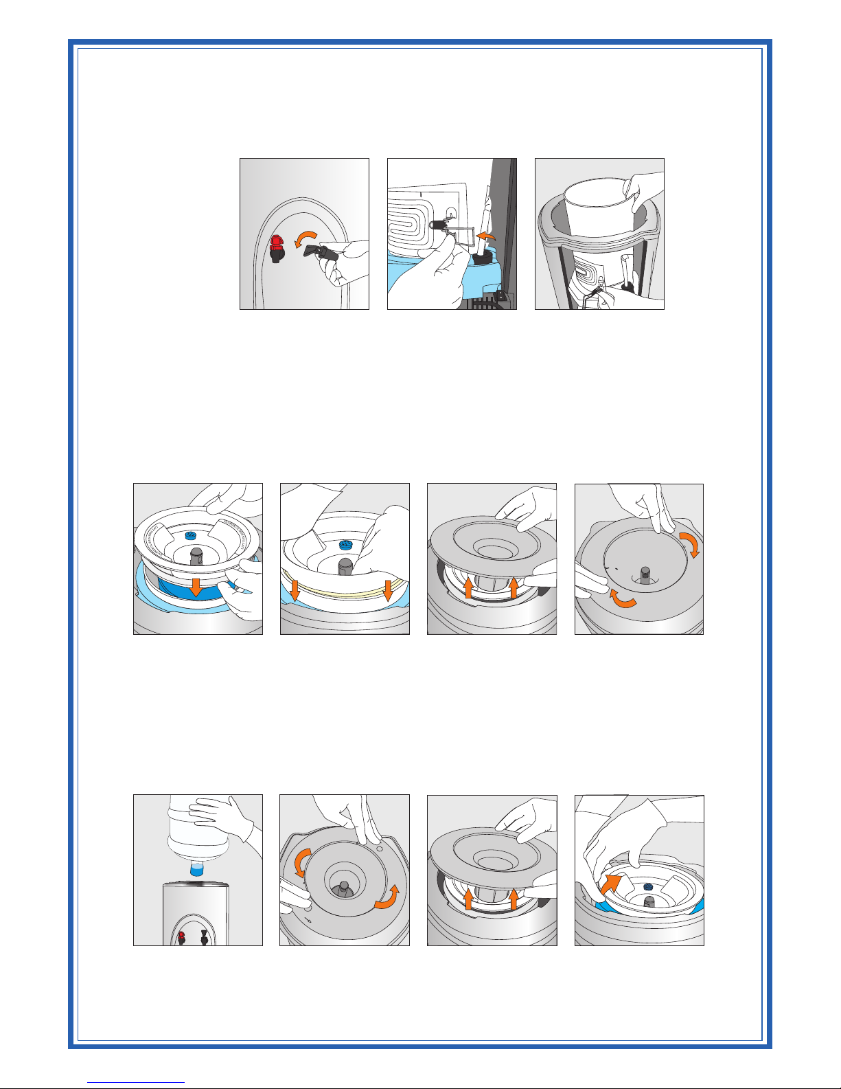
5. Approach the cooler from the rear and open the latch provided on the evaporator band (Figure 38).
6. Remove the faucets from the reservoir elbows by turning them counter clockwise (Figure 39).
7. Using both hands, loosen the reservoir from the evaporator band and lift it straight through the cooler
opening (Figure 40).
TM
DryGuard
Installation
TM
1. Place the Inner DryGuard Cone assembly onto the center of the cold water reservoir (Figure 41);
make sure the words “LIFT THIS SIDE TO REMOVE” is aligned with the sides of the cooler and
that the filter cap is positioned towards the rear of the cooler.
TM
2. Using the palms of both hands, push the DryGuard straight down into the reservoir (Figure 42).
TM
3. Install the Outer DryGuard Cover onto the cooler in the proper position on the body and lock into
place by turning clockwise until it fits tightly (Figure 43 and Figure 44).
Removal
1. Remove the bottle from the cooler (Figure 45).
TM
2. Loosen and remove the Outer DryGuard Cover from cooler’s body by pressing the fingertips of
both hands onto lid and turning it counter clockwise until it is free from the cooler opening (Figure
46 and Figure 47).
3. Approaching the cooler from left (or right), place one palm onto the top of the cooler on the side
furthest from you, and using your thumb, press downwards on the reservoir Insulation. Using your
TM
other hand, grip the edge of the Inner DryGuard Cone and pull it up slowly to remove. (Figure 48)
Warning: This cooler was manufactured using a high grade Stainless Steel. This material like other
metals remains sharp after it is formed. We, the manufacturer, would like to warn you against possible
injuries.
Figure 41 Figure 42 Figure 43 Figure 44
Figure 45 Figure 46 Figure 47 Figure 48
Figure 38 Figure 39 Figure 40
OP
E
N
O
P
EN
Page 8
OPTIONAL FAUCET COVER
Installation
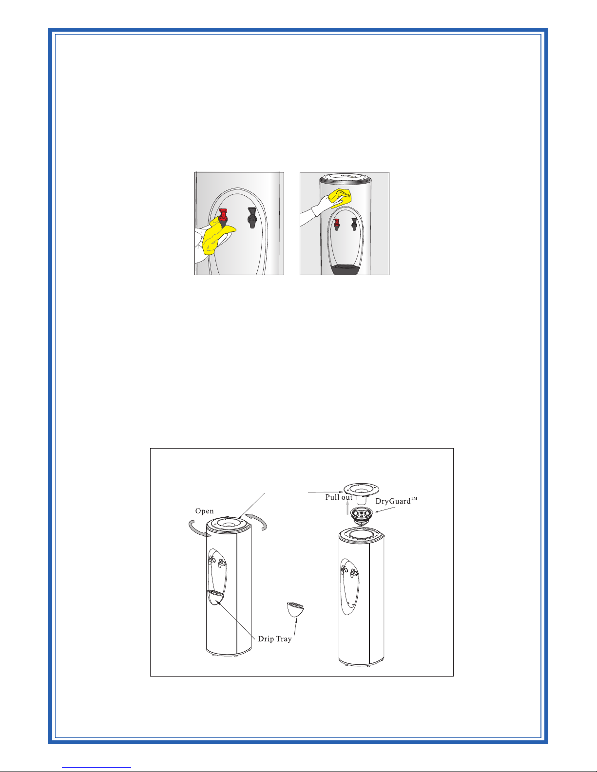
1. Ensure the faucet handles are straight, with the centrally located tabs towards the body. (Figure 51)
2. Hold the cover with the top angled away from the cooler body, and insert the lower taps of the
cover into the body and tilt the top of the cover up against the body and push down to lock into
place. (Ensure the faucet handles line up properly)
Removal
Pull upwards on the base of the cover to unlock and tilt the top outwards and down to remove.
CLEANING
Do Not Immerse the Unit in Water for Cleaning
Remove any dust or contaminants from the cooler by rinsing the cold water reservoir and faucets
with clean water prior to use. IMPORTANT: Stainless steel surfaces require special cleaning
products and treatment. Use only products specially formulated for use (Figure 49 and Figure 50)
TM
on stainless steel (Crystal Brite )
DO NOT USE abrasive cleaners or cloths when polishing
Figure 49 Figure 50
Removal and Installation of Outer DryGuard™ Cover and DryGuard™
TM
Outer D ryGuard Cover
Figure 51
Page 9
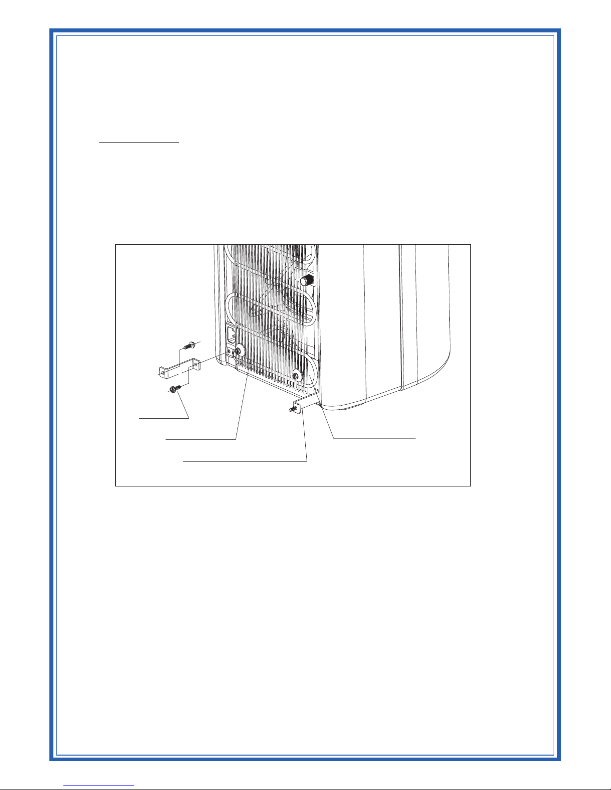
Standup Series Bracket Installation Instructions
INSTALLATION
1. Remove the two mounting screws that secure the Bottom Plate to the outer enclosure.
2. While holding the "S" shaped bracket against the cooler (refer to diagram) reinstall and
tighten the bottom plate/outer enclosure screws securely.
3. Place the cooler in position against the wall and using the "S" bracket, mark the location of
the wall insert holes to be drilled (if required). If not required, secure the cooler to the wall
using the two screws provided.
Figure 52
Screw
Condenser
Bottom Plate
"S" Mounting Bracket
Page 10
WARNING:
The warranty and Underwriters’ Laboratory and CE listings for the coolers are invalidated if
any alteration, modification, or use or misuse in combination with any other machine or
devices is deemed to be the source of any claim. The manufacturer accepts no liability
(including for bodily injury) resulting from any alteration, misuse, neglect, accidents, improper
installations or repairs.
The Red Faucet dispenses hot water during normal operation that may cause severe burns.
This appliance is not intended for use by persons (including children) with reduced physical,
sensory or mental capabilities, or lack of experience and knowledge, unless they have been
given supervision or instruction concerning use of the appliance by a person responsible for
their safety.
Children should be supervised to ensure that they do not play with the appliance.
If the supply cord is damaged, it must be replaced by a special cord or assembly available from
the manufacturer or its service agent.
This marking indicates that this product should not be disposed with other household
wastes throughout the EU. To prevent possible harm to the environment or human
health from uncontrolled waste disposal, recycle it responsibly to promote the
sustainable reuse of sustainable resources. To return your used device, please use the
return and collection systems or contact the retailer where the product was
purchased. They can take this product for environmental safe recycling.
The customer acknowledges that water, like other liquids, can cause damage to surfaces. The
customer takes full responsibility for placing the cooler within a residence or business, and
acknowledges that failure to address drips, leaks or spillages is at the customer’s risk.
Environmental application temperature: 10~32°C.
The unit is rated IP10. (This unit is not protected against ingress of water)
For more information on this product, please visit www.crystalcoolers.com
 Loading...