

UM-CV-RP1417-Q411V2 www.rackmountsales.com
User Manual
dedicated KVM switch and rackmount screen technology
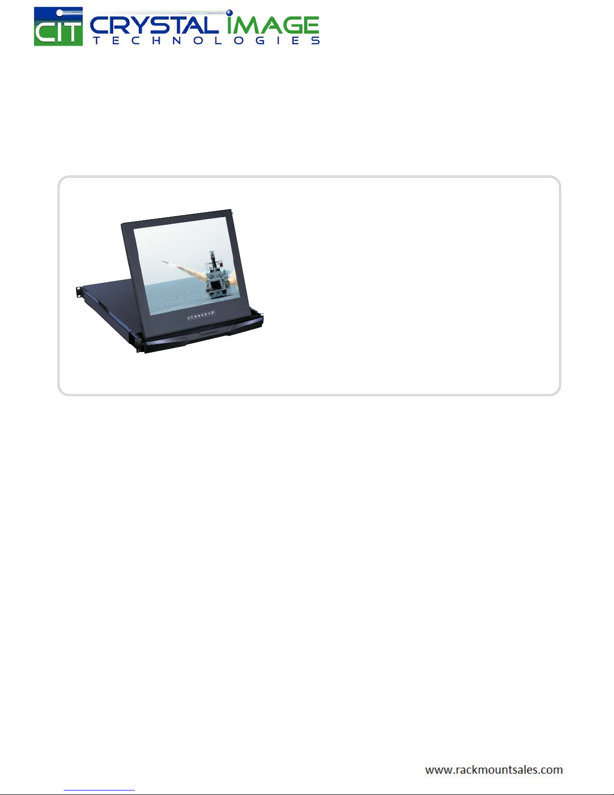
RMD-152-17 / 19
1U 17” / 19” Rackmount Display Drawer
Short depth version
Options :
- AV / DVI-D / HDMI
- Audio / DC power
- Touchscreen

UM-CV-RP1417-Q411V2 www.austin-hughes.com
Legal Information
First English printing, October 2002
Information in this document has been carefully checked for accuracy; however, no guarantee is given to the correctness
of the contents. The information in this document is subject to change without notice. We are not liable for any injury or
loss that results from the use of this equipment.
Safety Instructions
Please read all of these instructions carefully before you use the device. Save this manual for
future reference.
■ Unplug equipment before cleaning. Don’t use liquid or spray detergent; use a moist cloth.
■ Keep equipment away from excessive humidity and heat. Preferably, keep it in an air-conditioned environment with
temperatures not exceeding 40º Celsius (104º Fahrenheit).
■ When installing, place the equipment on a sturdy, level surface to prevent it from accidentally falling and causing dam
age to other equipment or injury to persons nearby.
■ When the equipment is in an open position, do not cover, block or in any way obstruct the gap between it and the
power supply. Proper air convection is necessary to keep it from overheating.
■ Arrange the equipment’s power cord in such a way that others won’t trip or fall over it.
■ If you are using a power cord that didn’t ship with the equipment, ensure that it is rated for the voltage and current
labeled on the equipment’s electrical ratings label. The voltage rating on the cord should be higher than the one listed
on the equipment’s ratings label.
■ Observe all precautions and warnings attached to the equipment.
■ If you don’t intend on using the equipment for a long time, disconnect it from the power outlet to prevent being dam
aged by transient over-voltage.
■ Keep all liquids away from the equipment to minimize the risk of accidental spillage. Liquid spilled on to the power
supply or on other hardware may cause damage, fi re or electrical shock.
■ Only qualifi ed service personnel should open the chassis. Opening it yourself could damage the equipment and invali
date its warranty.
■ If any part of the equipment becomes damaged or stops functioning, have it checked by qualifi ed service personnel.
What the warranty does not cover
■ Any product, on which the serial number has been defaced, modifi ed or removed.
■ Damage, deterioration or malfunction resulting from:
□ Accident, misuse, neglect, fi re, water, lightning, or other acts of nature, unauthorized product modifi cation, or
failure to follow instructions supplied with the product.
□ Repair or attempted repair by anyone not authorized by us.
□ Any damage of the product due to shipment.
□ Removal or installation of the product.
□ Causes external to the product, such as electric power fl uctuation or failure.
□ Use of supplies or parts not meeting our specifi cations.
□ Normal wear and tear.
□ Any other causes which does not relate to a product defect.
■ Removal, installation, and set-up service charges.
Regulatory Notices Federal Communications Commission (FCC)
This equipment has been tested and found to comply with the limits for a Class B digital device, pursuant to Part 15 of the
FCC rules. These limits are designed to provide reasonable protection against harmful interference in a residential installation.
Any changes or modifi cations made to this equipment may void the user’s authority to operate this equipment. This
equipment generates, uses, and can radiate radio frequency energy and, if not installed and used in accordance with the
instructions, may cause harmful interference to radio communications.
However, there is no guarantee that interference will not occur in a particular installation. If this equipment does cause
harmful interference to radio or television reception, which can be determined by turning the equipment off and on, the
user is encouraged to try to correct the interference by one or more of the following measures:
■ Re-position or relocate the receiving antenna.
■ Increase the separation between the equipment and receiver.
■ Connect the equipment into an outlet on a circuit different from that to which the receiver is connected.

UM-CV-RP1417-Q411V2 www.austin-hughes.com
Contents
< Part 1 >
RP-17 RP-19
1.1 Package Contents
1.2 Structure Diagram & Dimension
1.3 Installation
1.4 On-screen Display Operation ( OSD )
1.5 LCD Specifi cation
1.6 Options :
AV / DVI-D / HDMI
: Audio / DC Power
: T
ouchscreen & driver
P. 1
P. 2
P.3 - 4
P. 5
P. 6
P.7 - 8

UM-CV-RP1417-Q411V2 www.austin-hughes.com
+
- RP-1417 or RP-1419 X 1
- 6ft VGA cable X 1
- Power adapter & Power cord X 1
- M6 screw, cage nut & cup washer X 6
■ It is very important to mount the equipment in a suitable cabinet or on a stable surface.
■ Make sure the place has a good ventilation, is out of direct sunlight, away from sources of excessive
dust, dirt, heat, water, moisture and vibration.
The equipment comes with the standard parts shown in package content. Check and make sure they are
included and in good condition. If anything is missing, or damaged, contact the supplier immediately.
Unpacking
Before Installation
< 1.1 > Package Content
RP-1417 / 1419
< Part 1 >
P. 1
The above package content is only for the pure model ( VGA only ).
It varies with options such as AV, DVI-D, HDMI, audio, DC power & touchscreen.

UM-CV-RP1417-Q411V2 www.austin-hughes.com
P. 2
< 1.2 > Structure Diagram & Dimension
RP-1417 / 1419
Model
Product Dimension
(W x D x H)
Packing Dimension
(W x D x H)
Net
Weight
Gross
Weight
RP-1417 series
441.6 x 480 x 44.4 mm
17.4 x 18.9 x 1.75"
590 x 687 x 120 mm
23.2 x 27 x 4.7"
13 kg
29 lb
16 kg
35 lb
RP-1419 series
441.6 x 480 x 44.4 mm
17.4 x 18.9 x 1.75"
590 x 687 x 120 mm
23.2 x 27 x 4.7"
13 kg
29 lb
16 kg
35 lb
The product dimension will change from 480mm to 530mm in depth for the following :
- DVI option
- DC power option
- or change external power to internal power
The weight is only for the pure model ( VGA only ). It varies with accessories & options
such as AV, DVI-D, HDMI, audio, DC power & touchscreen.
LCD panel
“One Man” Installation Slide
LCD OSD membrane
1
2
Carry handle to release the 2-pt lock
2-point lock
3
4
5
1
2
3
4
5

UM-CV-RP1417-Q411V2 www.austin-hughes.com
P. 3
■ Attach the left and right mounting bracket to rack
19” mounting rails.
■ Adjust the rear mounting bracket to fi t your rack.
■ M6 screw and cup washer x 6 pcs included.
■ Pick up the display drawer.
■ Insert the display drawer into the mounting bracket.
■ Pull and hold the left & right black arrow buttons on
the rails.
■ Return the display drawer to park position.
Left front
Right front
Mounting bracket
Black arrow button
Left bracket
Right bracket
Front side
Rear side
■ Tighten all 8 pcs of M6 screw to complete the
installation.
■ Attach front left and right mounting ears of the
display drawer to vertical mounting rails.
■ M6 screw and cup washer x 2 pcs included.
Complete the installation
< 1.3 > Installation - How to install One Man Installation Slides
Step
4
Step
1
Step
2
Step
3
Caution : Leave the screws slightly loose,
until you complete the installation
in step
4

UM-CV-RP1417-Q411V2 www.austin-hughes.com
Figure 1.
LL
I
■ A black arrow release button is located on the
front of each slide. (shown in Figure 1).
Figure 2.
■ Pull and hold the black arrow button on either side
of the display drawer to unlock.
(shown in Figure 2).
L
I
Figure 3.
■ Push the display drawer into the rack.
(shown in Figure 3).
Caution : Keep your fi ngers away from the slide
stop
< 1.3 > Installation - How to Use the Slides
P. 4
RP-1417 / 1419
Power VGA

UM-CV-RP1417-Q411V2 www.austin-hughes.com
< 1.4 > On-screen Display Operation ( OSD )
Exit the OSD screen
Toggle analog, digital & video connection (DVI-D and video options only)
Scrolls through menu options and adjusts the displayed control
(To auto adjustment by pressing the button for 5 seconds)
Display the OSD menu
Power on / off LCD
Power light
Green = On
Orange = Power saving
Membrane Switch Function
OSD Confi guration Page
Image:
for the brightness, contrast, color temp, red, green, and blue
Geometry:
for the auto adjust, H position, V position, phase and clock
Video:
for the colour, tint, sharpness, noise reduction, DCDi and TV Setup
Audio:
for volume, bass, treble, balance, AVL and mute
Misc:
for the language, OSD position, graphic mode, ratio, reset and timer
P. 5

UM-CV-RP1417-Q411V2 www.austin-hughes.com
RP-1417 / 1419
P. 6
Item Description
LCD Manufacturer
Diagonal Size 17" TFT 19" TFT
Max. Resolution 1280 x 1024 1280 x 1024
Brightness (cd/m²) 250 250
Color Support 16.7 M 16.7 M
Contrast Ratio (typ.) 1000:1 1000:1
Viewing Angle (H/V) 160˚ x 160˚ 160˚ x 160˚
Active Area (mm) 338 x 270 376 x 301
Response Time Tr + Tf (ms) 55
LCD Panel MTBF (hrs) 50,000 50,000
VGA Signal Input Analog RGB, 0.7Vp-p
Sync. Type Separate H/V, Composite, SOG
Resolution
800 x 600, 60/ 70/ 72/ 75 Hz
1024 x 768, 60/ 70/ 75 Hz
1152 x 864, 60/ 70/ 75 Hz
1280 x 720, 60/ 70/ 75 Hz
1280 x 1024, 60/ 70/ 72/ 75 Hz
Plug & Play DDC EDID 1.3
Connector DB-15 connector
Power Input Auto-sensing 100 to 240VAC, 50 / 60Hz
Power Consumption Max. 48 Watt, Standby 5 Watt
Compatibility Multi-platform - Mix PCs, SUNs, IBMs, HPs & DELLs.
Regulation Approval FCC, CE
Environmental
Operation 0˚ to 50˚C Degree
Storage -5˚ to 60 ˚C Degree
Relative Humidity 5~90%, non-condensing
Shock 10G acceleration (11ms duration)
Vibration 5~500Hz 1G RMS random vibration
< 1.5 > LCD Specifi cation

UM-CV-RP1417-Q411V2 www.austin-hughes.com
< 1.6 > Options : AV / DVI-D / HDMI / Audio / DC power
HDMI Option
AV Option ( BNC + S-Video )
■ Option includes 1 x 6ft S-Video cable
P. 7
DC Power Option
Model 12V 24V 48V
Input rating
Input voltage: 12-Volt 24-Volt 48-Volt
Input range: 9 ~ 18V 18 ~ 36V 36 ~ 75V
Input current
- No load 50 mA 50 mA 50 mA
- Full load 4950 mA 2450 mA 1220 mA
Output rating
Output voltage: 12-Volt 12-Volt 12-Volt
Output current: 4.16A 4.16A 4.16A
Effi ciency 84% 85% 85%
Speaker
Left Right
DVI-D Option
■ Option includes 1 x 6ft DVI-D cable
■ Audio input is 35mm audio plug
■ The speaker is sharing the same power with LCD.
Audio Option
DC Power
VGA
■ Option includes 1 x 6ft HDMI cable
S-Video BNC
Power VGA
DVI-D
Power VGA
HDMI
Power VGA
Audio
Power VGA
The product dimension will change from 480mm to 530mm in depth for DVI-D option
The product dimension will change from 480mm to 530mm in depth for DC power option

UM-CV-RP1417-Q411V2 www.austin-hughes.com
< 1.6 > Options : Touchscreen & driver
RP-1417 / 1419
Model -17TRB / -17TRS -19TRB / -19TRS
Screen size 17" 19"
Interface USB / serial
Optical transmittance 80% ± 3%
Surface hardness ≥3H (JIS K5400)
Operating system Windows 98 / 2000 / ME / XP / NT / CE, DOS, Linux
P. 8
e-Capacitive Specifi cation
Model -17TCB / -17TCS -19TCB / -19TCS
Screen size 17" 19"
Interface USB / serial
Optical transmittance 93% ± 2%
Surface hardness >9H Surface hardness, withstand over 300 million touches
Operating system Windows 98 / 2000 / ME / XP / NT / CE, DOS, Linux
e-Resistive Specifi cation
■ USB touchscreen package includes 1 x 6ft USB cable, quick reference guideline and CD disc
■ Serial touchscreen package includes 1 x 6ft serial cable, quick reference guideline and CD disc
■ For detailed information, please refer to the attached CD disc
■ As the touchscreen unit is not made of toughened glass, please handle it carefully
■ Touchscreen in other brands are available on request
Please follow the below steps to setup the touch screen:-
Step 1. Run the bundled CD disc or download the driver from the link below :
http://www.austin-hughes.com > Downloads > CyberView > Driver & Software
Step 2. Double click the Setup.exe
Step 3. Follow the installation instruction to fi nish the setup
Step 4. After installation, run the TouchKit program & the “4 point calibration”
Please do the initial calibration
after the fi rst setup

 Loading...