

Page 1
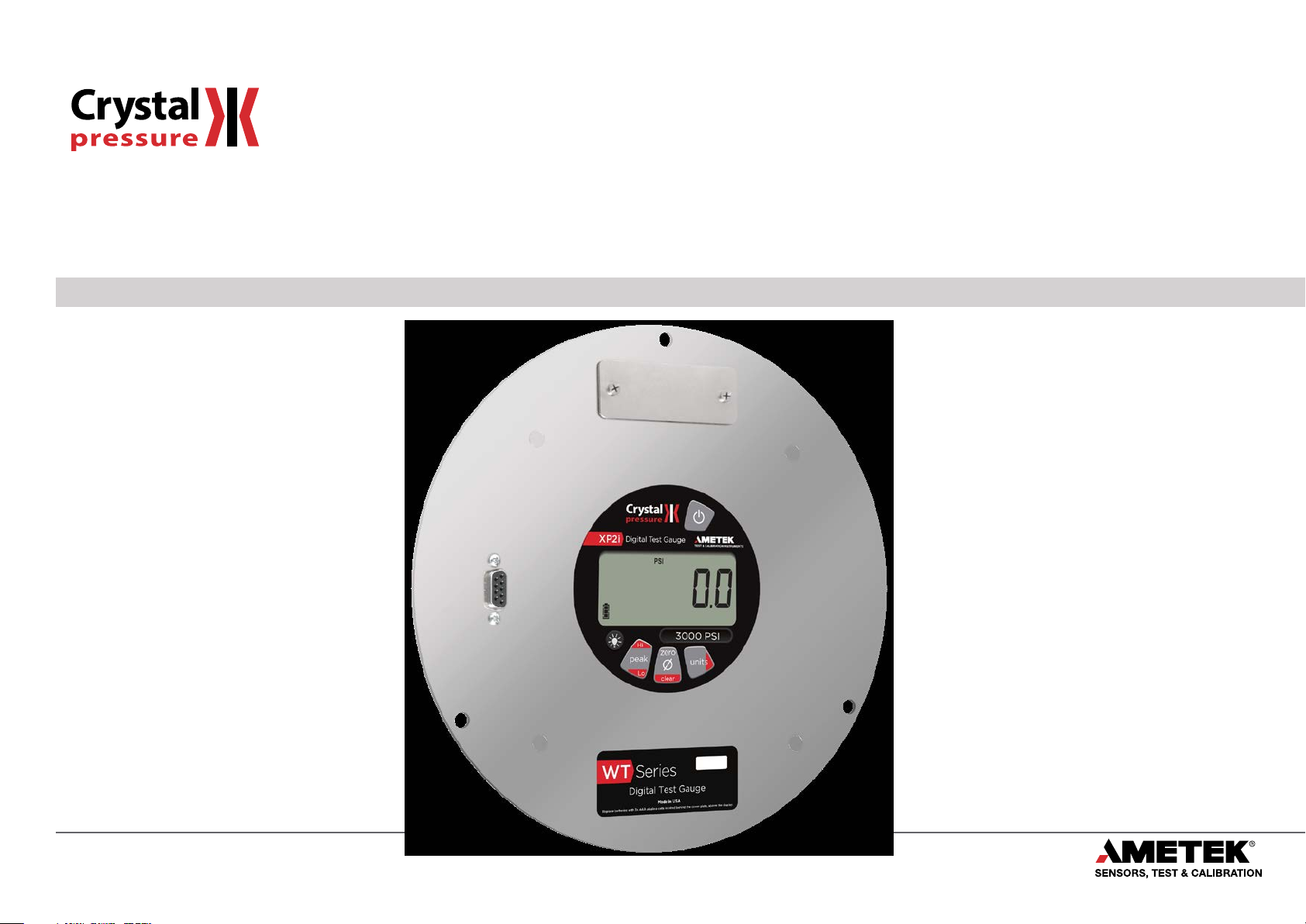
WT Series
Operation Manual
for the WT Series Digital Test Gauge
Page 2

Contents
Overview ............................................................. 1
Introduction .......................................................... 1
Operating Instructions ................................................. 2
Functions ............................................................ 3
Enclosure ........................................................... 10
Serial Numbers ....................................................... 10
Specifications ...................................................... 11
Power ................................................................ 12
Pressure Ranges, Display Scales, & Resolution .......................... 13
Part Numbering System ............................................... 13
Support .............................................................. 14
Troubleshooting ...................................................... 14
Calibration . . . . . . . . . . . . . . . . . . . . . . . . . . . . . . . . . . . . . . . . . . . . . . . . . . . . . . . . . . . 15
Software ............................................................. 16
Replacement Parts .................................................... 16
Accessories ........................................................... 16
Contact Us ........................................................... 17
Factory Service ....................................................... 17
Trademark ........................................................... 17
Warranty ............................................................. 17
Page 3
Overview
INTRODUCTION
Thank you for choosing the WT Series Digital Test Gauge from Crystal Engineering Corporation. The WT Series is a combination of leading edge technol-
ogy and rugged industrial design. The WT Series Digital Test Gauge is designed to t in 8" or 10" panel mount applications commonly found in portable test
. The WT Series is based on the Crystal Engineering Corp. model XP2i digital pressure gauge. The WT Series pressure gauge has been repackaged so that it
sets
may be mounted in a portable enclosure, while retaining easy access to batteries and to the digital (RS-232) interface (both of which would otherwise be on
the back of the gauge).
–
Accuracy is 0.1 percent of reading
–
so there is no change in accuracy throughout the entire operating temperature range!
sated
The WT Series’ case is made from rugged aluminum alloy utilizing a gasket to seal the enclosure against dust and water intrusion. Even the RS-232 connector
is fully sealed (with or without the red cover or rubber boot). Circuitry is mounted in shock absorbing elastomer supports and the batteries are easily acces-
sible by removing four screws. But you won’t need to change the batteries often, since 3 AAA batteries provide up to 500 hours of continuous operation. The
tteries are easily replaced by removing the two screws. Other features include:
ba
Continuous capture of peak and valley pressure readings
•
PSV mode
•
Programming interface
•
User-dened units
•
All welded 316 stainless steel sensor
•
so any WT Series can typically replace several gauges you may have been using. The WT Series is fully temperature compen-
Overview 1
Your WT Series can be customized, through
the use of our free CongXP™ software. Your
personal computer can disable, enable, or
modify a variety of features of your WT Series.
Look for the
logo for programmable features, like:
We hope your WT Series meets your expectations, and we're interested in any comments or suggestions you may have. You can send us a note at:
crystal@ametek.com. Many features in this and our other products are a direct result of your comments!
rystal Engineering is the company that designs, manufactures, markets, and services the nVision reference pressure recorder, XP2i, and 30 series pressure
C
calibrators, M1 Pressure Gauge, MultiCal multimeter pressure adapters, and a variety of industry specic pressure measuring equipment. Crystal Engineering
pioneered features like full temperature compensation and “of reading” rated gauges and calibrators. Pressure measuring equipment is the only thing we do
and that’s why we say:
™
A user dened pressure scale, and/or disable
•
unused pressure units
Password protection to prevent
•
unauthorized changes
Disable keypad recalibration, (peak)
•
button, and/or
Expand or decrease allowable Zero range
•
Set the gauge to a dierent density of water
•
factor (4° C, 60° F, or 68° F)
Store a 12 digit ID or tag number in
•
non-volatile memory
Adjust calibration values
•
(units) button
WT Series Operation Manual
Page 4
OPERATING INSTRUCTIONS
The WT Series is shipped with batteries installed, so it’s ready to use. Press and hold the (on/o) button. The WT Series will rst test all LCD seg-
ments. Release the
The WT Series always resumes operation in the mode and the units of the pressure last used, and it does not automatically rezero when turned on.
Connect the WT Series to your system.
CAUTION: Never insert any object into the pressure connection! The sensor diaphragm is very thin and can be damaged or destroyed by solid or sharp
!
WARNING: Severe injury or damage can occur through improper use of pressure instruments! Do not exceed recommended pressure limits of tubing
!
Most WT Series are intended for gauge pressure measurement. That is, they indicate the dierence between applied pressure and ambient barometric pres-
sure. However, the
factory default setting limits the maximum zero value to 20 PSI, but this limit can be changed with
Some WT Series are rated for absolute pressure. Absolute gauges indicate the dierence between applied pressure and an internal vacuum reference. Abso-
lute pressure is always positive. For instance barometric pressure at sea level is on average about 14.7 PSI (approximately 100 kPa or 1 bar), so at sea level this
is the lo
possible to indicate a negative or positive gauge pressure.
objects. Cleaning of the sensor must be done with appropriate solvents only.
and ttings. Be certain all pressure connections are secured.
(zero) button can be used to force a WT Series to read zero pressure at any applied pressure, up to the full scale rating of the gauge. The
west expected pressure indication. However, absolute gauges can be “zeroed” (unless prevented by CongXP). After zeroing an absolute gauge it is
(on/o) button when the WT Series indicates pressure.
.
Overview 2
WARNING: This gauge can display zero pressure when connected to a source of pressure! Do not rely on the display indication before disconnecting—
!
it may not be indicating true pressure. Never disconnect pressure instrumentation without rst relieving system pressure!
WT Series Operation Manual
Page 5
Functions
units
Units Button
Pressing this button causes the WT Series to select the next available unit of pressure measurement.
See Pressure Ranges, Display Scales, & Resolution on page 13 or the list of pressure units available for your model.
Units that you don’t need or never use can be turned o. You can also dene a special unit for your WT Series with CongXP.
You can use the WT Series to display directly in a unit not otherwise available, such as feet of seawater, or foot-pounds of torque. When you select your custom
unit from the keypad, the screen displays the USER icon.
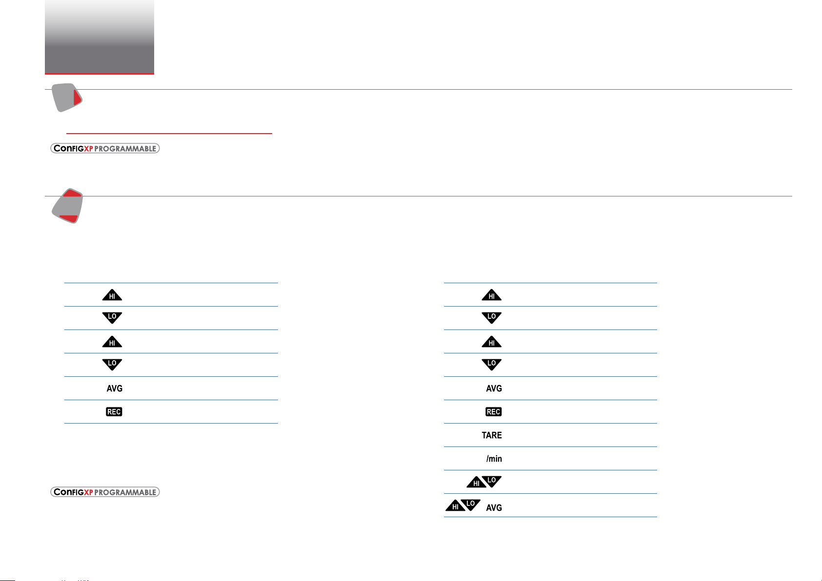
Hi
Peak Button
peak
Lo
Functions 3
On the WT Series, pressing the (peak) button causes the display to cycle
through the following , depending on your setting in CongXP.
<No Icon> . . . . Live Pressure display
. . . . Maximum detected pressure
. . . . Minimum detected pressure
(blinking)
(blinking)
. . . . PSV Mode, maximum
. . . . PSV Mode, minimum
Average pressure
. . . .
. . . . DataLoggerXP datalogging mode
*
*
* From the factory this setting is disabled. Use CongXP to enable.
Peak High and Peak Low values are not saved when the gauge shuts o; they will reset to the current
reading when the WT Series is turned on or reset.
In some cases the ability to display a peak value may not be needed, or
may even be dangerous. CongXP allows you to disable this button.
The WT Series can average 1 to 10 readings, recalculated every time pressure is measured (4 times per
second). Enable and set the number of readings to be averaged with CongXP.
On the -DD, dual-line display WT Series, pressing the
through the following, depending on your setting in CongXP:
<No Icon> . . . . Live Pressure display
. . . . Maximum detected pressure
. . . . Minimum detected pressure
(blinking)
(blinking)
. . . . PSV Mode maximum
. . . . PSV Mode minimum
. . . . Average pressure
. . . . DataLoggerXP datalogging mode
(remaining points displayed on lower line)
*
. . . . Tare
. . . . Rate of change
. . . . Dierential Mode
. . . . Average Dierential Mode
+
*
*
(peak)
*
*
*
button causes the display to cycle
WT Series Operation Manual
Page 6
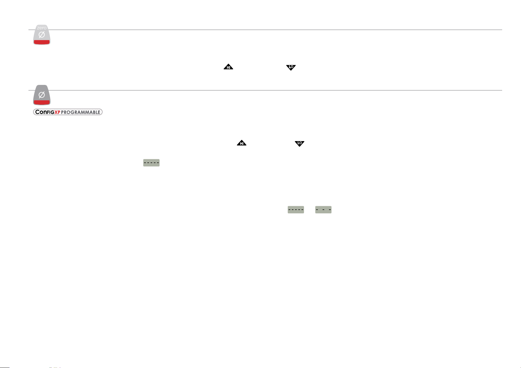
Resetting (Clearing) Recorded Peak Values
HI
LO
HI
LO
zero
zero
clear
Peak values can only be cleared when displaying either a Peak High or Peak Low recorded pressure. Press the (clear) button for at least ½ second. Dashed
lines will briey appear across the display indicating that both Peak values have been cleared. Both Peak High and Peak Low values will then display the
current applied pressure. Pressing the
(clear) button while either the Peak High icon (
value. If you need to rezero the gauge, you must turn o both peak icons by pressing the
) or the Peak Low icon (
(peak) button.
) is displayed will not aect the zero
Zero
clear
If you attempt to zero the gauge while applying a pressure which exceeds the Zero Limit (set in CongXP, defaults to 20 PSI),
the command will be ignored and - - HI - will be displayed.
X
To Zero the WT Series
Turn o peak indication by pressing the (peak) button repeatedly until the Peak High icon (
button for at least ½ second when the gauge is vented to atmosphere.
) and Peak Low icon (
) are o. Then press the (zero)
Functions 4
The display will then briey ash all dashed lines (
WARNING: This gauge can display zero pressure when connected to a source of pressure! Do not rely on the display indication before disconnecting—
!
), indicating that it has been re-zeroed. Absolute gauges will now indicate gauge pressure.
it may not be indicating true pressure. Never disconnect pressure instrumentation without rst relieving system pressure!
X
To Clear the Zero Value on the WT Series
Turn o peak indication as described above, then press and hold the (zero) button until the display changes from (
) to (
).
This is especially useful for absolute gauges that have been zeroed to use for gauge pressure measurement.
WT Series Operation Manual
Page 7

Functions 5
HI
LO
(
Tare
-DD, Dual-Line Display WT Series Only
Tare is a constant value subtracted from the true pressure. For instance, if you were mixing gases by partial pressure, you might want to ll a tank to 1760 psi
with air, then add another 440 psi of helium. To reduce the chance of error, you could tare the gauge at 1760 psi. Then you would add helium until the indica-
tion reached 440.
PSI
TARE
Fill to pressure Press the Tare button Top-o with helium
In contrast to the Zero function discussed previously, Tare is not subject to the Zero Limit set in CongXP. Tare is available only when the TARE icon is on. To
use the Tare feature, press the
not be indicated on the screen. Apply pressure to the gauge until you reach the desired value. Press the
pressure to zero. The amount of the tare will be displayed on the second line.
To clear the tare, press and hold the
(
Rate
-DD, Dual-Line Display WT Series Only
Rate is the measurement of pressure change per minute. When in Rate mode, the second line will display the rate, and the /min icon will display. Rate is
calculated at every pressure measurement (4 times per second), and the displayed value is the average of the most recent 3 to 10 calculations. By increasing
the number of calcula
(peak) button repeatedly until the screen displays the TARE icon. The TARE icon will ash to remind you that live pressure may
(zero) button until the tare value changes from (
The Tare function is disabled by default, but can be enabled with CongXP.
tions in the average, the WT will indicate a more stable rate. However, the WT will react more slowly to changes in rate.
TARE
)
PSI
TARE
PSI
(zero) button. The top line will change from true
) to (
)
).
To use the rate feature, press the
be set with the digital interface.
Dierential Mode
Dierential mode allows the WT Dual-Line Display gauge (the master) to be connected to a second WT gauge (the slave) and display the pressure dierence
between the two gauges. A standard RS232 cable (p/n 2400) and null modem adapter (p/n 3456) or a null modem cable are required to directly connect the
gauges. You must use CongXP to enable this feature, and once enabled, use the
Low (
ware version R0014 or later for this feature to work. Use DataLoggerXP version .6.10 or later to upgrade to the latest rmware.
) icons are displayed simultaneously. A WT Series gauge must be running rmware version R0114 or later, and a WT gauge must be running rm-
(
(peak) button repeatedly until the /min icon displays. As pressure changes, the second line will indicate rate of change.
The rate function is disabled by default, but can be enabled and congured with CongXP. The number of calculations can also
-DD, Dual-Line Display WT Series Only
The dierential mode is disabled by default, but can be enabled and congured with CongXP.
)
(peak) button on the master gauge until the Peak High (
) and Peak
WT Series Operation Manual
Page 8

Automatic Shut-o
The WT Series has a shuto timer and will turn o automatically after 20 minutes of non-operation. Pressing any button or sending any command via the RS-
232 connection resets the shuto timer for another 20 minutes of operation. The WT Series will briey display Auto O 20 when turned on.
Functions 6
To disable the shuto feature, turn on the WT Series by pressing the
No Auto O to indicate that it will not turn o. The shuto feature can be enabled again when turning the WT Series on, by pressing the same
(on/o) and (zero) buttons simultaneously. The WT Series will briey display the words
(on/o) and
(zero) buttons. These settings are retained when the product is powered down.
Note: This key combination will not toggle the auto-shuto feature if CongXP is set to require a password before changing settings.
Backlight
Pressing the (backlight) button instantly lights the display at maximum brightness. Hold down the button for 1 second to keep it on. The display will ash
briey, indicating that it will stay on for 1 minute. If you press the
battery life, and remain on for 2 minutes after the last key is pressed. Press the
If you start the WT Series in the No Auto O mode, you may select the brightness level in the same way. The light will never time out and turn o. Turn o the
WT Series, or press the
(backlight) button repeatedly, to turn o the backlight.
Measuring Vacuum
All versions of the WT Series can be used to measure moderate vacuum, though only ranges of 300 PSI (and 20 bar or 2000 kPa) and lower are actually tested
and certied for vacuum operation.
When measuring pressure less than ambient barometric conditions, a minus (-) sign will appear.
Absolute gauges (models with a “B” in front of “WT” in the part number) will NOT indicate a negative sign when vacuum is applied, unless the
has been pressed while a pressure greater than full vacuum is applied to the gauge. If your absolute gauge does indicate a negative pressure, you can clear
the zero value (“unzero”) by pressing the
CAUTION: WT Series are not recommended for continuous use below -14.5 PSIG.
!
(zero) button until the display changes from (
(backlight) button again, the backlight will go into a lower brightness setting to extend
(backlight) button once more and the light will go out.
(zero) button
) to (
).
For continuous use below -14.5 PSIG with high accuracy, choose our XP2i-DP Dierential Pressure Gauge.
WT Series Operation Manual
Page 9

Water Density (Inches of Water)
The following applies only to models where inches of water is a selectable pressure unit. As shipped from the factory, the WT Series is set to display inches of
water corresponding to the density of water at 4° C (39.2° F). You may require a dierent water density for your application, so the WT Series can be set to use
the density of water at 20° C (68° F) or 15.6° C (60° F) instead.
Functions 7
To check and/or change the water density setting from the keypad, turn on the WT Series by pressing the
ously. The display will indicate either 4C, 60F, or 68F.
ress the
P
Note: If the WT Series is password protected, or inches of water is disabled, you will not be able to view or change the water density from the keypad.
(units) button until the display cycles to the desired water density, then press the (zero) button to store the selection (this will not zero the gauge).
Select and set the desired density of water.
(on/o) button and the (peak) button simultane-
Overpressure Conditions
The WT Series will read pressure up to approximately 110% of the rated pressure range. Above 110% percent of the range the display will start ashing and
the readings will not be reliable. The zero function does not aect the point at which the display starts ashing to indicate overpressure, so depending on the
zero value it is possible that the display can start ashing without the maximum pressure being displayed.
For instance, if a 100 PSI WT Series is zeroed when 30 PSI is being applied, it will indicate that the overpressure condition has been reached at 80 PSI (i.e., 110%
x 100 PSI – 30 PSI = 80 PSI).
Overpressure can aect accuracy, but the eect is only temporary unless the sensor has been destroyed. See Pressure Ranges, Display Scales, & Resolution
on page 13 for maximum overpressure.
WT Series Operation Manual
Page 10

PSVtest Mode
HI
LO
HI
LO
PSVtest mode is designed for PSV and PRV (“Pressure Safety Valve” and “Pressure Relief Valve”, respectively) as well as for Rupture Disc (also known as “Burst
Disc”) testing. It increases the measurement rate of the WT Series gauge to approximately eight times per second, to capture the peak pressure when the
valve opened, and adds a method of automatically capturing the closing reseat pressure.
Functions 8
Use CongXP to activate PSVtest Mode. When the Peak High icon (
tomatically reset to the Peak High value whenever a new Peak High value is detected. Once pressure stops increasing, as when a PSV opens (and the pressure
ops below the maximum pressure) WT Series detects the new minimum pressure values (the Peak Low), capturing the closing pressure of a PSV.
dr
Press the
To clear the peaks, press the
Note: Application note AN-006
(peak) button once to view the captured reseat pressure. The Peak Low icon (
(clear) button while the display shows the Peak High icon (
–
Pressure Safety Valve Testing detailing the operation of the PSVtest mode is available on on our website and includes ex-
amples on how to use the gauge in relief valve and burst disk testing.
) ashes, PSVtest mode is enabled. A special feature of PSVtest is that Peak Low is au-
) will ash on the display.
) or Peak Low icon (
).
Reset
If for some reason the WT Series needs to be reset, remove any battery for at least one minute, then reinstall the battery. If the reset is successful, the WT Series
will start operating without pressing the
set to the default engineering units.
(on/o) button. Reset will clear the zero, peak values will be reset to the current reading, and the WT Series will be
Communications/Programming
The WT Series responds to a query-based command language which allows remote control of the gauge. Please refer to the XP2i Programming Instructions
for documentation of this feature.
WT Series Operation Manual
Page 11

Low Battery Indication
The Battery icon ( ) uses three bars to display the battery level. When the icon displays all three bars, the batteries are full. The WT Series will continue to
operate accurately while the icon is visible. When the batteries are exhausted, the letters batt will appear across the display. After batt appears, no pressure
measurements will be possible until the batteries are replaced.
Battery Replacement
The WTSeries gauge uses 3 AAA alkaline batteries. The batteries are located above the gauge behind a metal panel. With a small at blade screwdriver, un-
screw the two panel screws to gain access to the battery compartment. Remove the battery holder and slide the cover o. After replacing the batteries, the
gauge will star
t operating immediately (without having to press the button). This indicates that a complete reset has occurred, and is normal.
Functions 9
CAUTION: Do not mix battery types or manufacturers.
!
WT Series Operation Manual
Page 12

Enclosure
WT Series
Digital Test Gauge
Made in USA
Replace batteries with 3x AAA alkaline cells located behind the cover plate, above the display.
XP2i
Digital Test Gauge
Hi
Lo
peak
clear
zero
units
3000 PSI
Enclosure 10
INFORMATION
Weight . . . . . . . . . . . . . . . . . . . . . . . . . . 1.25 kg (2.7 lbs) (includes batteries)
Housing . . . . . . . . . . . . . . . . . . . . . . . . .Aluminum, Stainless Steel.
Keypad and Labels . . . . . . . . . . . . . . . UV Resistant Polyester.
BATTERY ACCESS (3 X AAA)
Ø 10.66
BOLT CIRCLE: Ø 10.125
Ø 9.25
BOLT CIRCLE: Ø 8.70
SERIAL PORT
(WITH COVER)
PIN 1
Serial Port Detail
Ø 0.28 THRU ALL
REAR COVER DIAMETER
3 PL
Ø 8.00
ALL DIMENSIONS IN INCHES
Dimensions in red are for the
1500 Panel Mount Flange option
120°
3 PL
3.80
PRESSURE PORT
POSITION
SERIAL NUMBERS
Serial Number Location
The serial number of your WT Series is located on the front panel. It is also stored
digitally within the gauge.
You may also nd your serial number using CongXP software. See CongXP for
more information.
Serial Numbering System
Serial Numbers consist of 6 numbers, with the left most digit representing the
year of manufacture. For example: 567358 was manufactured during 2015.
IDENTIFICATION LABEL
0.08
Panel
Thickness
Rear
ABS Cover
1/8"-27 FNPT
Pressure Port
1.11
2.41
Rear Cover
Mounting Screws
(4 Places)
0.30
WT Series Operation Manual
Page 13

Specifications
Accuracy
Includes all eects of linearity, hysteresis, repeatability, temperature, and stability for one year.
Gauges must be exercised whenever exposed to signicant changes in environmental conditions to achieve these specications, and (if not an absolute
model), rezeroed. To exercise a gauge, cycle the gauge between zero (ambient barometric pressure) and the pressure of interest. A properly exercised gauge
will return to a perfect zero reading (or return to the same ambient barometric reading).
Exposure to environmental extremes of temperature, shock, and/or vibration may warrant a more frequent recertication period.
20 to 100% of Full Scale . . . . . . . . . .±(0.1% of Reading).
0 to 20% of Full Scale . . . . . . . . . . . . ±(0.02% of Full Scale).
Vacuum, for 300 PSI, 20 bar, 2000 kPa, and lower pressure gauges:
±(0.25% of Full Scale), where F.S. = -14.5 PSIG, -1.0 bar, -100.0 kPa.
CAUTION: Not recommended for continuous use below -14.5 PSIG or 0.2 PSIA. Refer to the XP2i-DP data sheet for gauges that are intended for
!
continuous high vacuum use.
Specications 11
Temperature
Operating . . . . . . . . . . . . . . . . . . . . . . . -10 to 50° C (14 to 122° F).
Non-condensing. No change in accuracy over operating temperature range. Gauge must be zeroed to achieve rated specication.
Storage. . . . . . . . . . . . . . . . . . . . . . . . . .-40 to 75° C (-40 to 167° F).
Battery should be removed if stored for more than one month.
Media Compatibility
Liquids and gases compatible with 316 Stainless Steel.
WT Series Operation Manual
Page 14

Specications 12
Pressure Conversions
1 PSI = 27.6806 inches of water column (water at 4° C [39.2° F])
27.7070 inches of water column (water at 15.6° C [60° F])
27.7292 inches of water column (water at 20° C [68° F])
2.03602 inches of mercury (mercury at 0° C [32° F])
51.7149 millimeters of mercury (mercury at 0° C [32° F])
703.087 millimeters of water column (water at 4° C [39.2° F])
0.070307 kilograms per square centimeter
68.948 millibar
6.8948 kilopascals
0.068948 bar
0.006895 megapascals
Connections
Communication . . . . . . . . . . . . . . . . . DB-9, RS-232 (environmentally sealed).
Pressure Connection . . . . . . . . . . . . . 1/8" female NPT
Sensor
Wetted Materials . . . . . . . . . . . . . . . . (Wrench Tight) 316 stainless steel
(Finger Tight) 316 stainless steel and Viton (internal o-ring)
agm Seal Fluid . . . . . . . . . . . .Dow Corning 200
Diaphr
POWER
Batteries . . . . . . . . . . . . . . . . . . . . . . . .Three size AAA batteries.
WARNING: This product is not certied for use in hazardous locations.
!
Battery Life . . . . . . . . . . . . . . . . . . . . . .500 hours typical (alkaline battery).
Ultra Low Power . . . . . . . . . . . . . . . . . > 1 year, typical with 20 minute recording interval in LT5 mode.
Battery Indicator . . . . . . . . . . . . . . . . . 3-segment Battery Icon:
(
(
(
Dead Battery Indication . . . . . . . . . . batt
) : Full Battery
) : Used Battery
) : Low Battery
Display
Screen . . . . . . . . . . . . . . . . . . . . . . . . . .5.5 digits.
Display Rate . . . . . . . . . . . . . . . . . . . . .4 readings/second (standard).
8 readings/second (PSV mode).
ical Display Height . . . . . . . .16.9 mm (0.67”) single line display. LCD readable in sunlight with
Numer
bright backlight.
WT Series Operation Manual
Page 15

PRESSURE RANGES, DISPLAY SCALES, & RESOLUTION
Specications 13
PSI bar kPa MPa Overpressure PSI
15PSI 1BAR 100KPA 0.1M PA 6.5 x 0.0 01 0.01 0.0 01 0.01 1 0.0001 0.0001 0.1 0.01 0.00001
30PSI 2BAR 200KPA 0.2 MPA 3.0 x 0.001 0.01 0.001 0.1 1 0.0001 0.0001 0.1 0.01 0.00001
100PSI 7BAR 700KPA 0.7MPA 2.0 x 0.01 0.1 0.01 0.1
300PSI 20BAR 2KKPA 2M PA 2.0 x 0.01 0.1 0.01 1 0.0 01 0.0 01 1 0.1 0.0001
500PSI 30BAR 3KKPA 3MPA 2.0 x 0.01
1KPSI 70BAR 7KKPA 7MPA 2.0 x 0.1 0.1 0.0 01 0.0 01 0.1 0.0001
2KPSI 14 0BAR 14KKPA 14M PA 2.0 x 0.1 0.1 0.01 0.01 1 0. 001
3KPSI 200BAR 20KKPA 20M PA 1.5 x 0.1 0.1 0.01 0.01 1 0. 001
5KPSI 300BAR 30KKPA 30 MPA 1.5 x 0.1
10KPSI 700BAR 70KKPA 70 MPA 1.5 x
Unneeded pressure units may be disabled via the RS-232 connector using CongXP software.
•
kPa and MPa models can display pressure in kPa, MPa, and bar (or mbar) only. PSI and bar models can display all available units.
•
WT Series will indicate pressure up to 10% above Range Pressure. Above 110%, the display will ash, indicating that the applied pressure exceeds the
•
calibrated pressure range. If the calibrated pressure range is exceeded, the pressure displayed may not be accurate.
Absolute pressure WT Series gauges are designated by a “B” following the part number.
•
An Absolute pressure version is available only on ranges of 2000 PSI and higher.
•
in
H20 inHg mmHg mmH20 kg/cm
1
1
0.1
1
1
1
2
bar mbar kPa MPa
0.0001 0.0001 0.1 0.01 0.00001
0.0 01 0.0 01
0.01 0.01 1 0. 001
0.01 0.01 1 0. 001
1
0.1 0.0001
PART NUMBERING SYSTEM
Model P/N Gauge Type Panel Mount Dual Display? Data-logging?
WT
Standard: (omit)
Absolute: B 10.125”: -1500
Absolute only available
on 2KPSI gauges and
higher
SAMPLE PART NUMBERS
WT300PSI-1000 .........300 PSI standard WT Series gauge with 8.7" bolt centering panel
WT2KPSIB-1500 .........2000 PSI standard WT Series Absolute gauge with 10.125" bolt centering panel
WT30KKPA-1500-DL ....30 000 kPa standard WT Series gauge with 10.125" bolt centering panel, with DataLoggerXP rmware
8.7”: -1000
No .....(omit)
Yes .......-DD
No: (omit)
Yes: -DL
WT Series Operation Manual
Page 16

Support
TROUBLESHOOTING
The WT Series is a very high performance gauge. Due to the high resolution of this product, you may observe conditions that appear to be defects in the prod-
uct, but are in fact a result of being able to resolve and measure pressure to a degree not possible with other instruments.
Support 14
Noisy or Unstable Reading When Used with Fluids
When calibrating or comparing the indicated pressure from a WT Series against a hydraulic dead
–
weight tester or piston gauge, the reading on the WT may appear unstable
digit jumps up and down several counts.
X
Reason: Gas (usually air) is trapped in the line between the gauge and the deadweight tester.
What is actually happening is the mass is oscillating up and down, and the combination of gas
and uid is acting like a spring. At higher pressures (above 2000 PSI, typically) this may eventually
diminish, as the gas dissolv
X
Solution: Evacuate all tubing with a vacuum pump, before introducing uid into the system.
es into the uid.
the least signicant
Non-repeatability of Pressure Measurements
When checking the gauge against a hydraulic deadweight, increasing pressure measurements
do not match decreasing pressure measurements.
X
Reason: As in the previous note, gas has dissolved into the hydraulic uid. When decreasing the
pressure, the dissolved gas then leaves the uid, but at an uneven rate, so small pressure dieren-
tial (due to uid head pressure) may exist between the reference deadweight and the gauge being
ested.
t
X
Solution: Evacuate all tubing with a vacuum pump, before introducing uid into the system.
Err 2 Displayed
X
Reason: The WT has tried to display a number too large for the display (i.e., more than 5 digits).
May be due to an electrical malfunction or numerical error.
X
Solution: Contact factory for further instructions.
Err 4 Displayed on -DD, Dual Line Display Gauge.
X
Reason: The gauge is a master in dierential mode that cannot detect the slave device.
X
Solution:
1 Turn on the slave gauge.
2 Ensure you are using a null modem RS232 cable or standard cable with a null modem adapter.
3 Use CongXP to remove the dierential mode from the gauge.
Err 5 or Err 6 Displayed
X
Reason: The WT pressure sensor is exhibiting out of normal operating condition behavior.
X
Solution: Contact factory for sensor replacement.
Err 1 Displayed
X
Reason: The WT checks the integrity of internal calibration coecients every time it’s turned on.
If any coecients have been corrupted in any way, “Err 1” is displayed.
X
Solution: Contact factory for instructions on how to restore the memory to the original factory
settings.
WT Series Operation Manual
Page 17

CALIBRATION
Factory Adjustment
If adjustment is required, we recommend returning the unit to the factory. Factory service oers benets you won’t nd anywhere else. We have the facilities
to test your gauge at a variety of temperatures utilizing NIST traceable standards in our A2LA accredited laboratory, resulting in calibration certicates that
provide performance data over temperature. Furthermore, upgrades may be available to add or enhance operating features. We designed the product to last,
and we support it so that you can get the most from your investment.
Calibration Frequency
Under normal operating conditions, we recommend the WT be calibrated on an annual basis. Your quality system may require more or less frequent calibra-
tion, or your experience with the gauge, or operating environment may suggest longer or shorter intervals.
lthough we prefer that you return the WT to Crystal Engineering for calibration, ordinary recertication and/or adjustments may be performed by any quali-
A
ed personnel with appropriate training and equipment.
Span Factor
There are no internal potentiometers. The WT contains a “span” factor, set to approximately 1 (as shipped from the factory). As components age this may need
to be changed to a value slightly higher or lower, to slightly increase or decrease all readings. This adjustment can be made with or without a computer (see
CongXP Conguration Software).
Support 15
X
Span Factor adjustment
Note: The following instructions are ONLY intended for such qualied personnel with appropriate test equipment. We recommend that the calibration stan-
dards used have a minimum rated accuracy of 0.025% of reading, or equivalent in terms of percent of full scale. This level of accuracy requires the use
on (deadweight) gauges or very high performance pressure controllers.
of pist
“Zero” the WT, then record displayed pressure for two or more pressure points. Determine if the WT would benet from an overall increase or decrease of the
indicated pressures.
To change the span factor from the keypad, turn o the WT, then press the
be briey displayed, followed by the word cal, followed by the actual span value. The span factor may be adjusted by pressing either the
button to increase or decrease the value, respectively. The value changes in 0.0001 increments. Press the
(on/o) button to cancel the change.
the
For absolute WTs, it is possible to correct for long term drift using a second calibration factor, zero value oset. CongXP and a barometric reference with ac-
curacy of 0.1 PSI or better is required to perform the calibration. To calibrate the zero oset, clear the zero as described earlier in this manual by pressing and
holding the
zero value oset in CongXP, and update the gauge (new value = barometric – displayed + existing). For example, if the displayed value is 14.5 PSI, barometric
pressure is 14.7 PSI, and the existing zero value oset in CongXP is 0.1 PSI, the new zero value oset would be 0.3 PSI (14.7 - 14.5 + 0.1 = 0.3).
can be disabled by CongXP through the disable span factor feature or by password protecting the WT .
(zero) button until (
The span factor and zero value oset can be viewed and set directly by CongXP. Span factor adjustment through the keypad
) appears. Once cleared, subtract the displayed pressure from barometric pressure, add this dierence to any existing
(on/o), (units), and (peak) buttons simultaneously. The rmware version will
(units) or (peak)
(zero) button to store the new value in memory, or
XP
WT Series Operation Manual
Page 18

SOFTWARE
CongXP Conguration Software
Use CongXP to disable unwanted pressure units, set default pressure units, change water density, adjust calibration, and more via the RS-232 interface.
REPLACEMENT PARTS
The only user-replaceable parts are the batteries.
ACCESSORIES
P/N 2984 AC adapter kit
Permits operation of a WT Series from an AC supply of 90 - 264 VAC and 47 - 63 Hz. Includes interchangeable international plugs (for USA, Europe, U.K., and Australia).
Adapter will not charge batteries, but in the event of AC power loss, WTs will automatically revert to battery operation.
P/N 3313 USB-RS232 Adapter
USB B receptacle to RS232 DB9M.
P/N 2400 RS232 Cable
DB-9 male to DB-9 female straight pass-through cable.
Support 16
WT Series Operation Manual
Page 19

CONTACT US
Phone . . . . . . . . . . . . . . . . . . . . . . . . . .(805) 595-5477
Toll-Free . . . . . . . . . . . . . . . . . . . . . . . . (800) 444-1850
Fax . . . . . . . . . . . . . . . . . . . . . . . . . . . . . . (805) 595-5466
Email . . . . . . . . . . . . . . . . . . . . . . . . . . .crystal@ametek.com
Web . . . . . . . . . . . . . . . . . . . . . . . . . . . . . ametekcalibration.com
FACTORY SERVICE
Please complete the Return Material Authorization (RMA) form. It will generate an authorization number and provide return instructions.
TRADEMARK
“Pressure is Our Business” is a registered trademark of Crystal Engineering Corp.
WARRANTY
Support 17
Crystal Engineering Corporation warrants the WT Series Digital Test Gauge to be free from defects in material and workmanship under normal use and service
for one (1) year from date of purchase to the original purchaser. It does not apply to batteries or when the product has been misused, altered or damaged by
accident or abnormal conditions of operation.
Crystal Engineering will, at our option, repair or replace the defective device free of charge and the device will be returned, transportation prepaid. However, if
we determine the failure was caused by misuse, alteration, accident or abnormal condition of operation, you will be billed for the repair.
CRYSTAL ENGINEERING CORPORATION MAKES NO WARRANTY OTHER THAN THE LIMITED WARRANTY STATED ABOVE. ALL WARRANTIES, INCLUDING IMPLIED
WARRANTIES OF MERCHANTABILITY OR FITNESS FOR ANY PARTICULAR PURPOSE, ARE LIMITED TO A PERIOD OF ONE (1) YEAR FROM THE DATE OF PURCHASE.
CRYSTAL ENGINEERING SHALL NOT BE LIABLE FOR ANY SPECIAL, INCIDENTAL OR CONSEQUENTIAL DAMAGES, WHETHER IN CONTRACT, TORT OR OTHERWISE.
Note: (USA only) Some states do not allow limitations of implied warranties or the exclusion of incidental or consequential damages, so the above limitations
or exclusions may not apply to you. This warranty gives you specic legal rights and you may have other rights which vary from state to state.
WT Series Operation Manual
Page 20

3310.F 1907
© 2019 Crystal Engineering Corporation
708 Fiero Lane, Suite 9, San Luis Obispo, California 93401-8701
 Loading...