

Page 1
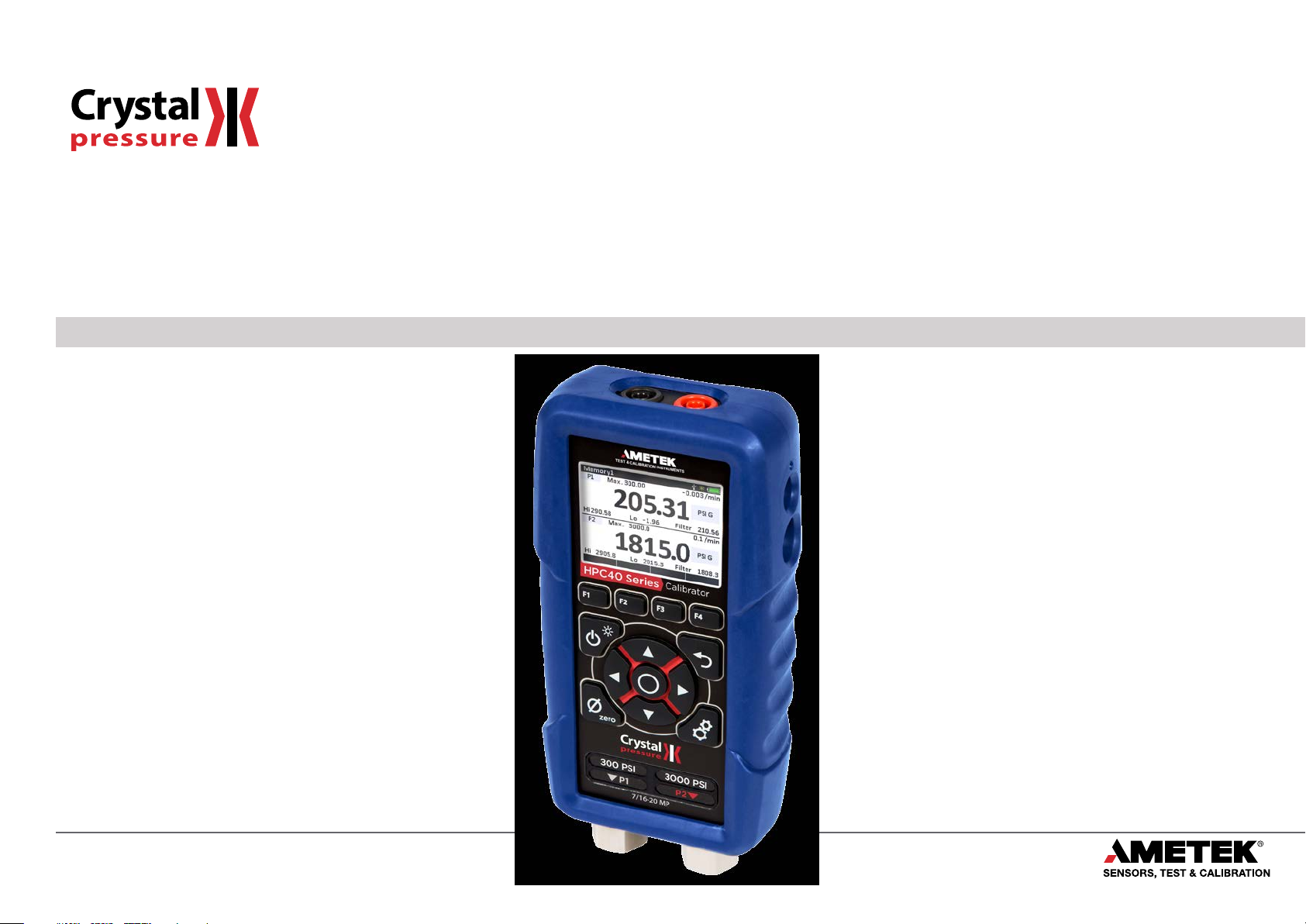
HPC40 Series
Operation Manual
for the HPC40 Series Handheld Pressure Calibrator
Page 2

Contents
Overview...............................................................1
Introduction ............................................................1
Quickstart ..............................................................2
Functions ..............................................................3
On/O..................................................................3
Navigation..............................................................3
Settings ................................................................5
Display .................................................................8
Operation..............................................................9
Pressure Sensors ........................................................9
Measuring Current .....................................................13
Sourcing Current.......................................................14
Measuring Voltage .....................................................16
Measuring Temperature (RTD) ..........................................17
Performing a Switch Test ...............................................18
Calibrating a Pressure Transmitter.......................................19
Enclosure .............................................................21
Specifications .......................................................22
Ranges and Resolutions ................................................27
Certications ..........................................................27
Support ...............................................................28
Troubleshooting .......................................................28
Calibration ............................................................29
Accessories and Replacement Parts .....................................30
Contact Us.............................................................31
Warranty ..............................................................31
Page 3

Overview
INTRODUCTION
Thank you for choosing the HPC40 Series handheld pressure calibrator from Crystal Engineering Corporation. HPC40 calibrators feature deadweight tester
accuracy in a modern digital package with the safest tting connection available. The new full color display also features a new easy to use interface similar to
the one used in the JOFRA ASC-400 Series. The HPC40 is available as a stand-alone calibrator or in one of our complete pump systems, and may be used in a
broad range of applications from simple tool type jobs to complex calibration jobs in custody transfer systems.
Overview 1
Accuracy is up to 0.035 percent of reading
temperature compensated
Single and dual pressure sensor models are available from vacuum up to 15 000 psi / 1000 bar. In addition, the HPC40 features the ability to add an external
pressure port (APM) to provide up to 3 pressure ports. When included with a barometric reference (BARO option), all pressure readings can be displayed as
gauge or absolute readings.
In addition to pressure measurement, the HPC40 also includes a full set of electrical connections. Inputs are included for mA, voltage, switch testing, and
temperature measurement (RTD). An internal 24 VDC supply is also included to power mA transmitters.
HPC40 Series Measurement Options
Measurement Type Available Modes (as dened on display)
Pressure P1, P2, APM, Di. Pres, Dual Pres.
Temperature RTD In
Barometric Pressure BARO
Current mA in, mA Out
Voltage VDC In
Switch Tes t Switch Tes t
Other features include:
User congurable information display
•
% error calculation
•
Damping
•
Leak Testing
•
Min/Max hold
•
Uses Crystal’s new CPF ttings and hose system (leak-free and nger-tight to 10 000 psi (700 bar))
•
– so there is no change in accuracy throughout the entire operating temperature range!
– so one HPC40 can typically replace several gauges or calibrators you may have been using. The HPC40 is fully
We hope your HPC40 meets your expectations, and we’re interested in any comments or suggestions you may have. You can send us a note at:
crystal@ametek.com. Many features in this and our other products are a direct result of your comments!
rystal Engineering is the company that designs, manufactures, and services the nVision reference recorders, XP2i series pressure gauges, 30 series pressure
C
calibrators, and a variety of industry specic pressure measuring equipment.
HPC40 Series Operation Manual
Page 4
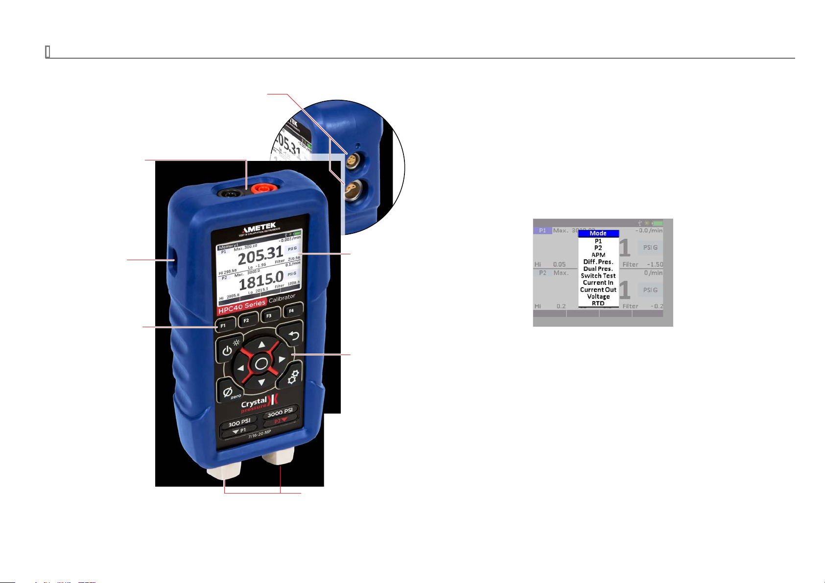
QUICKSTART
display combined with the
“Wireless” Keypad
APM and Temperature Connection
Connect to an external APM module to expand
the pressure options, plus a high accuracy RTD to
read temperature.
Overview 2
All input and output
connectors are placed
away from the display and
keypad to give maximum
freedom to operate.
Mini-USB Port
Customize the set-up through
free CrystalControl software.
Function Buttons
The function of each
button is clearly explained
on the bottom of the
display.
Color Display
The new large full-color
advanced simplicity of the
new user interface, makes
the HPC40 Series the
easiest-to-use pressure
calibrator available.
Cursor Keys
Cursor keys help you to
navigate through the
display to perform set up
functions and ne tune
values.
Unique “Non-Menu” User Interface
Easy to use single layer user interface. No deep menu structure!
Operate and set up the HPC40 Series to perform your tasks quickly
and intuitively.
CPF Pressure Connections
Includes patented, leak-free, nger-tight
CPF connection ttings.
HPC40 Series Operation Manual
Page 5
Functions
ON/OFF
Power button
Press and hold the (power) button to turn the HPC40 Series on or o.
The HPC40 will automatically power down if not used for the time period dened in the unit settings or in CrystalControl.
Automatic Shuto - Low Power Mode
To optimize battery life, adjust your Automatic Shuto time (shut o time in absence of key press) on the unit or through the free
CrystalControl software.
This feature is adjustable from 5 minutes to “always on.”
Functions 3
When powered by USB, the HPC40 does not employ any power management strategies.
CrystalControl.
NAVIGATION
Arrow Buttons
The (arrow) buttons serve dierent functions depending on the mode of operation. Press any of the four (arrow) buttons to enter “Naviga-
tion Mode”. In this mode, the user can scroll through editable elds directly onscreen. Any eld that can be edited will be highlighted in blue.
Navigation Mode: Use the four
Edit Mode: Use the Up and Down
(arrow) buttons to scroll through lists of options. Or, if entering a number, use the left and right
(arrow) buttons to move the cursor in the desired direction.
(arrow) buttons to move the cursor one character in the desired direction.
Back Button
Press the (back) button to cancel a selection or to return to a previous menu.
Enter Button
Press the (enter) button to view/accept selected options or entered values. When a value is entered with the (enter) button, the cursor selects
the next value eld in the list.
Therefore, it will not automatically shut o to the settings dened by
HPC40 Series Operation Manual
Page 6
Zero Button
Press the (zero) button to activate the function key options. The HPC40 will display the parameters that are currently shown on the upper and
lower displays. Press the
zero
(-----), indicating that it has been zeroed.
Note: If you attempt to zero the gauge with more pressure applied than the Zero Limit set on the HPC40 (or with CrystalControl) the command will be
ignored, and Over Zero Limit will display.
ote: The BARO sensor cannot be zeroed.
N
WARNING: This calibrator can display zero pressure when connected to a source of pressure! Do not rely on the display indication before disconnecting—
!
X
To Clear the Zero Value
1 Press the (zero) button to activate the (function) buttons for the available pressure sensors.
it may not be indicating true pressure. Never disconnect pressure instrumentation without rst relieving system pressure!
(function) button for the parameter that you would like to zero. The display will then briey ash all dashed lines
Functions 4
2 Press and hold the
X
To Clear the Peaks
1 Press the (zero) button to activate the (function) buttons for the available pressure sensors.
2 Press the
(function) button for Peaks to reset the P1, P2, and APM peaks.
(function) button for the sensor that you would like to unzero until the display changes from (- - - - -) to (- - -).
Navigating Through a Typical Setup
1 Press any of the (arrow) buttons to enter Navigation Mode. Editable elds will be highlighted in blue.
2 Use the
3 Use the (enter) button to select a eld for editing.
(arrow) buttons to move between the congurable elds within the upper and lower displays. Selected elds will be highlighted in dark blue.
HPC40 Series Operation Manual
Page 7
4 Use the up and down (arrow) buttons to select a new value, then press the (enter) button to choose the new value.
Select a Value… then press enter.
Note: To exit Navigation mode without making a selection, press the (back) button.
SETTINGS
Settings Button
Press the (settings) button to enter the system settings menu.
Functions 5
X
Recall
Used to recall a saved setup.
X
Save
Used to store the current display setup. Saving a setup allows for quick loading of the same congurations for later use. This makes it easy to switch between
dierent applications or tasks. Up to 5 setups can be stored.
X
General
Used to view or edit the following system settings:
Auto O Time
•
HART resistor On/O
•
Battery Chemistry
•
Serial Number
•
Firmware Version
•
Part Number
•
HPC40 Series Operation Manual
Page 8

X
P1, P2, and APM
Mode: Switch between absolute and gauge pressure.
•
Filter Time
•
Zero Limit
•
Custom Engineering Unit
•
Serial Number
•
Range
•
Maximum Resolution: When a resolution less than standard is selected, the displayed number will include an asterisk (*).
•
View Calibration Details
•
X
RTD In
Dene Custom RTD
•
Serial Number
•
Maximum Resolution: When a resolution less than standard is selected, the displayed number will include an asterisk (*).
•
View Calibration Details
•
X
mA In, mA Out, VDC In
Serial Number
•
Maximum Resolution: When a resolution less than standard is selected, the displayed number will include an asterisk (*).
•
View Calibration Details
•
Functions 6
HPC40 Series Operation Manual
Page 9
X
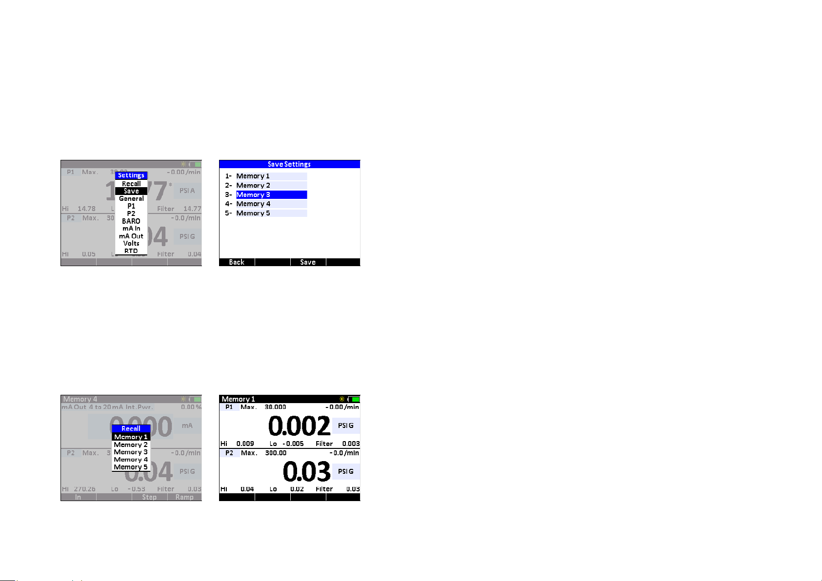
To Save a Setup
After you have congured the unit, you can save the setup for future use.
Functions 7
1 Press the
2 Press the
3 Press the
4 Use the
The name is limited to eight characters.
Highlight the settings to modify... then change the name of the saved setup.
5 Press the (F3) function button for Save.
X
To Recall a Setup
1 Press the (settings) button to enter the settings section.
2 Press the
3 Press the
(settings) button to enter the settings section.
(arrow) buttons to highlight the Save Setting, and the press the (enter) button.
(arrow) buttons to highlight the setup you want to modify, and then press the (enter) button.
(arrow) buttons to change the name of the saved setup. When nished press the (enter) button.
(arrow) buttons to highlight the Recall Setting, and then press the (enter) button.
(arrow) buttons to highlight the setup you want to use, and then press the (enter) button.
The name of the setup will appear in the upper-left corner
Highlight the setup… then press enter.
HPC40 Series Operation Manual
Page 10

DISPLAY
The display is divided into two sections: the upper and lower displays. The upper display can be congured to show values for Current, Voltage, RTD, Pressure,
BARO, or Switch Test. The lower display can be congured to show values for only RTD, Pressure, and BARO.
Upper Display (showing Current)
Lower Display (showing Pressure)
Functions 8
HPC40 Series Operation Manual
Page 11

Operation
PRESSURE SENSORS
The HPC40 Series is equipped with one or two pressure sensors. In addition, a Crystal APM (Advanced Pressure Module) may also be used. For information on
the Crystal APM, please refer to the APM CPF Series Operation Manual. Be sure to choose the proper sensor based on working pressures and accuracy.
WARNINGS: The following warnings apply to any sensor used with the HPC40 — whether internal or external:
!
Pressure sensors may be damaged and/or personal injury may occur due to improper application of pressure. Please refer to the
•
Ranges and Resolutions table for information on overpressure ratings.
Operation 9
The calibrator will display
•
to prevent damage or possible personal injury.
Note:
+
OL is displayed when the pressure exceeds 110% of the nominal range of the sensor.
+
OL when an inappropriate pressure is applied. If + OL is displayed, the pressure should be reduced or vented immediately
Pressure Connection
Crystal CPF System: Medium Pressure Female (MPF) (1/4” medium pressure tube system with 7/16-20 threads). See our CPF brochure for further information.
CPF o-ring size and material: AS568A-012, Viton 80 or 90 durometer (P/N 3981).
For most applications CPF Fittings can be hand tightened (no tools required). Wrench tightening is recommended (to achieve a metal to metal cone seal) for
applications where chemical compatibility of the process uid and the o-ring are a concern. Cone seals require only moderate assembly torque to seal up to
10 000 PSI (700 bar). We recommend a tightening torque of 120 in-lbs ±20 in-lbs for our CPF ttings. Please note this is only a fraction of the typical torque
required to seal a 1/4” NPT tting. If a torque wrench isn’t practical to use, the ttings can be assembled as follows: Hand tighten tting fully
until the cone has bottomed out, then tighten an additional 20° using a hex wrench. Apply a small amount of media-compatible lubricant to the gland
thr
eads and male cone to increase tting life, reduce the likelihood of galling, and promote sealing.
CAUTION: To achieve CPF maximum allowable working pressures no o-ring substitutions are allowed. See our CPF brochure and
!
CES-003 CPF Safety Guide available from the website at ametek.com for further detail.
Measuring Vacuum
All versions of the HPC40 can be used to measure moderate vacuum.
When measuring pressure less than ambient barometric conditions, a minus (-) sign will appear.
CAUTION: The HPC40 is not recommended for continuous use at high vacuum.
!
HPC40 Series Operation Manual
Page 12

Overpressure Conditions
The HPC40 Series will read pressure up to approximately 110% of the rated pressure range. Above 110%, the display will indicate + OL, and readings will stop
+
updating. The zero function does not aect when the display will indicate
without the maximum pressure being displayed.
For instance, if a 100 psi range is zeroed when 30 psi is being applied, it will indicate that the overpressure condition has been reached at 80 psi
(i.e., 110% x 100 psi – 30 psi = 80 psi).
verpressure can aect accuracy, but the eect is only temporary unless the sensor has been destroyed. See the Ranges and Resolutions table for maximum
O
allowable overpressure ratings.
OL, so depending on the zero value it is possible that the display will indicate + OL
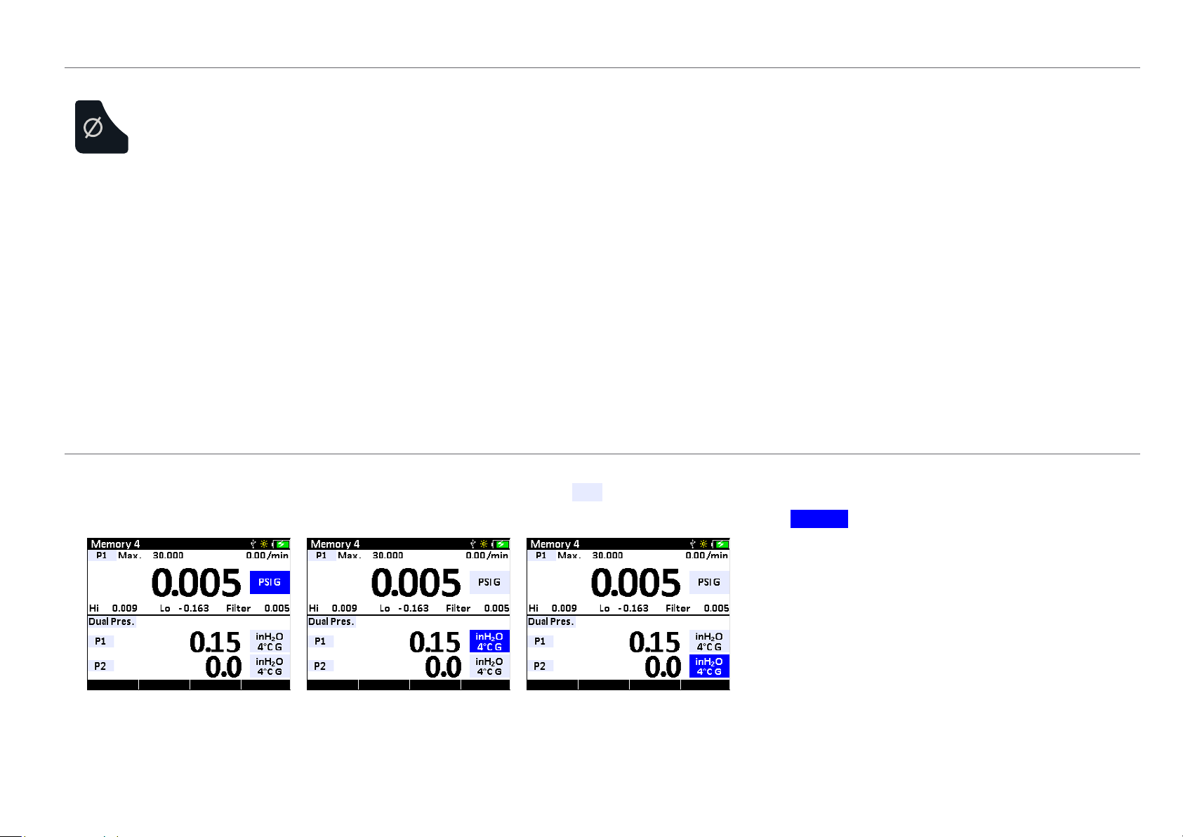
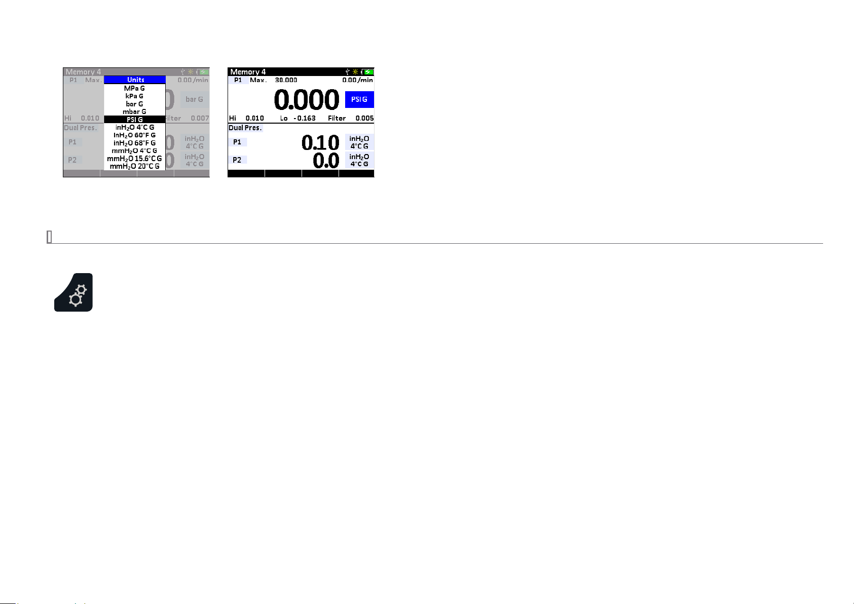
Measuring Pressure
X
To Measure Pressure
1 Connect the HPC40 using an appropriate tting.
2 Select one of the pressure modes: P1 , P2 , APM , BARO , or Dual Pres .
For more information on working in the HPC40 display, see Navigating Through a Typical Setup.
3 From the HPC40 display, select the desired pressure units.
Operation 10
Select a pressure mode... then select a pressure unit.
4 Apply pressure to the device under test.
X
Absolute Pressure (BARO Option)
See P1, P2, or APM settings to toggle between absolute and gauge pressure.
HPC40 Series Operation Manual
Page 13

X
To Zero the Calibrator
1 Press the (zero) button to activate the (function) buttons for the available pressure sensors.
Operation 11
2 Press the
The display will change to dashed lines (- - - - -) and the reading will be zeroed.
Zeroing the P2 sensor.
X
To Clear the Zero Value
1 Press the (zero) button to activate the (function) buttons for the available pressure sensors.
2 Press and hold the
X
To Clear the Peaks
1 Press the (zero) button to activate the (function) buttons for the available pressure sensors.
2 Press the
3 Press the
(function) button for the sensor that you would like to zero.
(function) button for the sensor that you would like to unzero until the display changes from (- - - - -) to (- - -).
(function) button for Peaks to reset the P1, P2, and APM peaks.
(function) button for the peaks you would like to clear. The Hi, Lo, and Filter will all display (- - - - -).
Note: If you attempt to zero the gauge with more pressure applied than the Zero Limit set on the HPC40 (or with CrystalControl) the command will be
ignored, and Over Zero Limit will display.
ote: The BARO sensor cannot be zeroed.
N
WARNING: This calibrator can display zero pressure when connected to a source of pressure! Do not rely on the display indication before disconnecting—
!
it may not be indicating true pressure. Never disconnect pressure instrumentation without rst relieving system pressure!
Dierential Pressure
The HPC 40 Series can display dierential pressure when 2 or more sensors are installed (including external APM). The modules do not have to be the same full
scale pressure range.
HPC40 Series Operation Manual
Page 14

X
To Display Dierential Pressure
1 Select Di. Pres. from the Mode section.
2 Choose the two sensors that you want to use for dierential pressure.
3 Choose the unit for the dierential reading.
For more information on working in the HPC40 display, see Navigating Through a Typical Setup.
4 Apply pressure to one or both sensors to read the dierential.
The two pressure sensors being used can be changed from P1, P2, or APM.
Dierential Pressure Unit
Static Pressure Unit
Note: The static pressure is also displayed on the bottom of the window. The unit for the static pressure does not have to be the same as the dierential unit.
Tare
Operation 12
Using the Tare function improves your dierential measurement uncertainty signicantly if used properly. The Tare function equalizes (normalizes) the
HPC40’s two modules at a non-ambient datum.
If you apply the same static line pressure to both sensors simultaneously, you should have a dierential reading of zero. Due to the allowable error tolerance
for each module, the reading may not be zero. The Tare function allows you to normalize both readings so that the dierential reading is zero. This gives you a
more accurate dierential reading than if this process were not completed.
Note: Tare should be reestablished every time your measurement conditions change, including vent condition. For instance if your ΔP reading has 8 inH20 of
Tare at 1500 psi static, when you return to vent condition this 8 inH20 of Tare will remain in place on your ΔP reading until cleared with the Tare button.
To Tare:
1 Use the
2 Press the
3 Press the
Note: You will notice that the word Tare is now included on the top right of the display to indicate that the sensors have been tared.
4 To clear the Tare value in the Dierential Mode, hold the
(arrow) buttons to navigate to the Dierential Mode view.
(zero) button to activate the function button options.
(function) button for the ( ) icon.
(function) button for the ( ) icon for four seconds until the dierential display readings
change from (- - - - -) to (- - -). The tare indication will now be removed from the display.
HPC40 Series Operation Manual
Page 15

MEASURING CURRENT
The HPC40 is capable of measuring current in four dierent modes:
mA Measured current is displayed (mA). The module is capable of measuring inputs up to 55 mA.
•
0-20 mA Current is displayed as a percentage of the 0-20 mA current range of the module. Where: 0 mA = 0%, and 20 mA = 100%
•
4-20 mA Current is displayed as a percentage of the 4-20 mA current range of the module. Where: 4 mA = 0%, and 20 mA = 100%
•
10-50 mA Current is displayed as a percentage of the 10-50 mA current range of the module. Where: 10 mA = 0%, and 50 mA = 100%
•
X
To Measure Current
1 Select mA In .
For more information on working in the HPC40 display, see Navigating Through a Typical Setup.
2 In current mode, the numerical value displayed represents the current measured at the test lead inputs. In the top right corner is a percentage value based
on whether 0 to 20 mA , 4 to 20 mA , or 10 to 50 mA is selected.
For example, if the measured current is 16 mA and the selected scale is 4 to 20 mA, the percent will display as 75%.
Operation 13
Measuring Current.
3 Select Ext. Pwr. from the power source list if the mA loop is already powered, or Int. Pwr. to have the HPC40 supply the power.
Int. Pwr. is not available in the 10-50 mA range.
4 Connect the HPC40 using the appropriate test leads.
5 The HPC40 will display the measured current.
Note: The display will indicate
Note: For details on % error and scaling features see page 20.
+
OL if the measured current exceeds the nominal range of current measurement (55 mA).
HPC40 Series Operation Manual
Page 16

SOURCING CURRENT
The HPC40 is capable of sourcing up to 25 mA.
X
To Source mA (Internal Loop Power Supply)
1 Select mA Out.
2 Select the appropriate range (0-20 or 4-20) if you will be sourcing based on the % of the scale.
3 Choose Int. Pwr. from the power source list.
4 Choose either mA (to output a specic mA signal), or % (to output based on the % of the mA range).
5 Connect the HPC40 using the appropriate test lead connections.
Operation 14
6 Enter the desired current in mA or % to source.
X
mA Sink (External Loop Power Supply)
1 Select mA Out.
2 Select the appropriate range (0-20 or 4-20) if you will be sourcing based on the % of the scale.
3 Choose Ext. Pwr. from the power source list.
4 Choose either mA (to output a specic mA signal), or % (to output based on the % of the mA range).
5 Connect the HPC40 using the appropriate test lead connections.
6 Enter the desired current in mA or % to sink.
HPC40 Series Operation Manual
Page 17

X
mA Step
The HPC40 has the ability to automatically or manually step through the mA range at predened intervals.
1 Select mA Out.
2 Select the appropriate mA range (0-20, 4-20).
3 Select Ext. Pwr. from the power source list if the mA loop is already powered, or Int. Pwr. to have the HPC40 supply the power.
Operation 15
4 Press the
5 Enter the 0 and 100% mA points. For example, if you’re sourcing to a 4-20 mA loop, enter 4 for the 0% point and 20 for the 100% point.
6 Choose the step size from 10%, 20%, or 25%. This is the percent of the mA range that will be increased with each step.
7 Enter the time between each step you would like to use.
8 Press the (function) button for Auto, and the HPC40 will automatically start the step process.
9 Press the
new function keys -Step (decreasing a single step) and +Step (increasing a single step) are now available.
X
mA Ramp
The HPC40 has the ability to provide a consistent ramp throughout the full mA range.
1 Select mA Out.
(function) button for Step.
(function) button for back when nished. Or, if you would like to pause the step function and increase manually, press Stop. If you press Stop,
2 Select the appropriate mA range (0-20, 4-20).
3 Select Ext. Pwr. from the power source list if the mA loop is already powered, or Int. Pwr. to have the HPC40 supply the power.
4 Press the
5 Enter the 0 and 100% mA points.
(function) button for Ramp.
HPC40 Series Operation Manual
Page 18

6 Enter the total time to get from 0 to 100% of the scale.
7 Press the (function) button for Start and the HPC40 will begin the ramp process.
Operation 16
8 Press the
MEASURING VOLTAGE
The HPC40 may be used to measure voltages up to 30VDC. Voltage measurements are limited to the upper display.
X
To Measure Voltage
1 Select VDC In .
For more information on working in the HPC40 display, see Navigating Through a Typical Setup.
2 Connect the HPC40 using the appropriate test leads.
3 The HPC40 will indicate the measured voltage.
Note: The display will indicate
(function) button for Stop to pause the ramp, or Back to go back to the ramp setup screen.
+
OL if the measured voltage exceeds the nominal range of voltage measurement (30 VDC).
HPC40 Series Operation Manual
Page 19

MEASURING TEMPERATURE RTD
Your HPC40 has the ability to measure temperature very accurately using “true ohm” technology. True ohm resistance measurement eliminates temperature
reading errors by compensating for thermoelectric eects associated with the wires and connections between the RTD and the HPC40. The HPC40 will also
indicate electrical resistance (Ω) to help in troubleshooting your resistance based sensing element.
RTDs are characterized by their 0° C resistance, R0. The HPC40 accepts -2, -3, and -4 wire inputs, with 4 wire input being the most accurate.
The HPC40 is compatible with a large number of platinum RTD probe types. Ametek oers a platinum 100 probe that is ready to connect directly to the
HPC40’s RTD port. See Accessories and Replacement Parts for details.
X
To Measure Temperature
1 Select RTD In .
For more information on working in the HPC40 display, see Navigating Through a Typical Setup.
2 In RTD mode select an RTD type from the RTD Type list.
Operation 17
Select RTD... then select an RTD type.
3 Select a wire connection from the Num Wires list: 2-wire , 3-wire , or 4-wire .
4-wire allows for the most accurate measurement
4 Select the appropriate unit from the list.
5 Connect your RTD probe to the HPC40.
If you have our probe (PN 127387), plug it in to the HPC40’s RTD port and select probe type P100(90)385, 4-wire. If you wish to connect your own RTD
probe, you may do so by connecting your probe wires per the HPC40 RTD port diagrams below, and using a mating connector from Lemo’s 1S.304 series.
4 wire
1
2
3
4
3 wire
2-wire 3-wire 4-wire
4 wire
1
2
3
4
3 wire
4 wire
1
2
3
4
3 wire
6 The HPC40 will display the measured temperature.
Note:
+
OL will be displayed if the probe resistance is greater than 400 Ohms and/or the calculated temperature is outside the range dened for the probe.
Temperature range depends on the probe type.
HPC40 Series Operation Manual
Page 20

PERFORMING A SWITCH TEST
Performing a switch test will require the use of both screens. The HPC40 records switch state, and pressure or temperature measurement at the time of switch
change. After the test, the result is displayed in a convenient and easy-to-use format.
X
To Perform a Switch Test
1 Select Switch Test in the upper display.
2 FOR A PRESSURE SWITCH, select P1, P2, Di. Press., or APM in the lower display.
FOR A TEMPERATURE SWITCH, select RTD In in the lower display.
For more information on working in the HPC40 display, see Navigating Through a Typical Setup.
3 Connect the HPC40 to the switch using the terminals on the top of the HPC40. (The polarity of the terminals does not matter.)
4 FOR A PRESSURE SWITCH, connect a pump to the HPC40 and then to the switch.
FOR A TEMPERATURE SWITCH, connect an RTD to the HPC40 connection and place the RTD and temperature sensor in a temperature calibrator.
5 Check that the vent on the pump is open, and zero the calibrator if necessary. Then close the pump vent.
The upper display will show no read outs for the Closed, Opened, and Dead band values.
Operation 18
6 Slowly apply pressure or temperature until the switch opens.
Once the switch is open, the switch icon will change to (
Note: In the switch test mode, the display update rate is increased to ten readings per second to help capture the changing switch state. Even with this en-
hanced sample rate, pressurizing the device under test should be done slowly to ensure accurate readings.
), and the display will indicate pressure at which the switch opened.
HPC40 Series Operation Manual
Page 21

7 Decrease pressure or temperature until the switch closes.
Once the switch closes, the icon will change to (
Switch Open Switch Closed
8 To perform a new test, highlight the reset option and press the (enter) button.
The Closed, Opened, and Dead band value will all be blank again.
Note: The procedure is the same whether the default mode for the switch is opened or closed. So for example, applying pressure or temperature to an open
switch will cause the switch to close, and the icon will change to (
CALIBRATING A PRESSURE TRANSMITTER
When calibrating a transmitter, both the upper and lower displays are used. Pressure and Temperature Transmitters with ranges of 0 to 20 mA, 4 to 20 mA, and
10 to 50 mA can be calibrated by an HPC40. The example below will use a 4 to 20 mA pressure transmitter.
) and the Closed value and Dead band value will be indicated.
) as in step 7 above.
Operation 19
X
To Calibrate a Pressure Transmitter
1 Select mA In in the upper display and P1 in the lower display.
2 Select 4 to 20mA from the Range list.
3 Select Ext. Pwr. from the power source list if the mA loop is already powered, or Int. Pwr. to have the HPC40 supply the power.
Select 4 to 20mA... then select Int. Pwr. or Ext. Pwr.
4 Connect the HPC40 to the transmitter.
HPC40 Series Operation Manual
Page 22

X
HART Resistor
The HPC40 has an internal 250 Ohm HART resistor that can be selected if desired. With the (settings) button, choose General to select HART resistor
On or O.
X
Percent Error Function
The HPC40 can be programmed to calculate a deviation or % error from 4-20 mA output. This eliminates the need for manual calculations and can also be
helpful if it becomes dicult to set an exact pressure with an external pump. The HPC40 simultaneously displays pressure, mA, and percent error.
1 Select % Error from the mA units selection in the upper window.
Operation 20
2 Use the
3 Increase pressure to the desired point and the HPC40 upper display will indicate the % error as well as the actual mA value. The lower display will show the
X
Scaling Function
The HPC40 has the ability to read current or voltage in the upper display that is scaled to and displayed in the same units as the lower display. This makes it
much easier to compare a mA reading to a known accurate pressure reading.
1 Select Scaling from the mA units selection in the upper window.
2 Use the
3 Increase pressure to the desired point and the HPC40 upper display will indicate the equivalent pressure based on the mA reading, as well as the actual mA
(arrow) buttons to set the 0 and 100% points for both the mA and pressure ranges of the transmitter.
measured pressure.
(arrow) buttons to set the 0 and 100% points for both the mA (or VDC) and pressure ranges of the transmitter.
value. The lower display will show the measured pressure.
HPC40 Series Operation Manual
Page 23

Enclosure
ADDITIONAL SENSOR LENGTH WITH OPTIONAL FITTING ADAPTERS
CONNECTOR
INFORMATION
Weight . . . . . . . . . . . . . . . . . . . . . . . . . . 689 g (24.3 oz) (includes batteries).
Housing . . . . . . . . . . . . . . . . . . . . . . . . .Machined aluminum; hard anodized.
Rating . . . . . . . . . . . . . . . . . . . . . . . . . . .IP65.
Keypad and Labels . . . . . . . . . . . . . . . UV Resistant Silicone.
88.6
(3.49)
Enclosure 21
MINI USB
176.3
(6.94)
164.6
(6.48)
300 PSI 15K PSI
34.9
(1.38)
mA CONNECTIONS
Ø 4 mm SHIELDED BANANA JACKS
REMOTE PRESSURE
MODULE CONNECTION
RTD CONNECTION
SENSOR DIAPHRAGM
7/16 -20 M P
CPF PORTS
SUR FACE
22.7
(0.90)
19.1
(0.75)
41.5
(1.63)
1/4 INCH MNPT
ADAPTER
29.1
(1.15)
1/4 INCH MBSP
ADAPTER
26.1
(1.03)
32.6
(1.30)
M20X1.5
ADAPTER
HPC40 Series Operation Manual
Page 24

Specifications
Gauge Pressure Accuracy
Includes all eects of linearity, hysteresis, repeatability, temperature, and stability with the operating temperature range for one year.
Note: Exposure to environmental extremes of temperature, shock, or vibration may warrant a more frequent calibration period.
The HPC40 Series must be exercised and re-zeroed whenever exposed to signicant changes in environmental conditions to achieve these specications. To
exercise a gauge, cycle the gauge between zero (ambient barometric pressure) and the pressure of interest. A properly exercised gauge will return to a zero
reading (or return to the same ambient barometric reading).
X
Gauge Pressure (psi)
• 18 to 28° C
0 to 30% of Range . . . . . . . . . . . . . . . . . . ±(0.01% of Full Scale)
30 to 110% of Range . . . . . . . . . . . . . . . . ±(0.035% of Reading)
Vacuum
• -20 to 50° C
0 to 30% of Range . . . . . . . . . . . . . . . . . . ±(0.015% of Full Scale)
30 to 110% of Range . . . . . . . . . . . . . . . . ±(0.050% of Reading)
Vacuum
*
**
. . . . . . . . . . . . . . . . . . . . . . . . . . . ±(0.05% of Full Scale**)
*
. . . . . . . . . . . . . . . . . . . . . . . . . . . ±(0.05% of Full Scale**)
*
Applies to 300 psi and lower ranges only.
Full Scale is the numerical value of the positive pressure range.
Specications 22
CAUTION: Not recommended for continuous use below -14.5 psig. Refer to the XP2i-DP data sheet for gauges that are intended for continuous high
!
X
Absolute Pressure with BARO Option (psiA)
All absolute accuracies are equivalent to the gauge pressure accuracies, except as noted below.
30 psi Range . . . . . . . . . . . . . . . . . . . . . . . Gauge Accuracy + 0.005 psiA
100 psi Range . . . . . . . . . . . . . . . . . . . . . . Gauge Accuracy + 0.002 psiA
vacuum use.
HPC40 Series Operation Manual
Page 25

X
Dierential Pressure
The Tare function can improve dierential pressure measurement uncertainties. Requires the use of an equalizing valve. Use the higher range sensor specica-
tion when two dierent ranges are selected.
Full Scale Range of Both Sensors The Greater of (+/–)
psi psi mbar inH
30 0.0005 0.04 0.014 0.4
100 0. 0015 0.10 0.04 1.0
300 0.005 0.4 0.14 4.0
1000 0.02 1.0 0.4 10. 0 or
3000 0.05 4.0 1.4 n/a
10000 0.2 10.0 4.0 n/a
15000 0.3 15.0 6.0 n/a
Unit is enabled in CrystalControl
O mmH2O % of DP Reading
2
0.035%
• Without tare function:
± (0.05% of static line pressure reading)
Barometric Reference
Accuracy . . . . . . . . . . . . . . . . . . . . . . . . ± 0.00725 psi, ± 0.5 mbar
Specications 23
Accuracy specications include all eects of linearity, hysteresis, repeatability, temperature, and stability within the specied operating temperature range for
one year.
Note: Exposure to environmental extremes of temperature, shock, and/or vibration may warrant a more frequent recertication period.
Pressure Sensor (P1 and P2)
Wetted Materials. . . . . . . . . . . . . . . . .(wrench tight) 316 stainless steel
(
finger tight) 316 stainless steel and Viton® (internal o-ring)
Diaphragm Seal Fluid: . . . . . . . . . . . .Silicone Oil
Connection: . . . . . . . . . . . . . . . . . . . . .Crystal CPF Female
HPC40 Series Operation Manual
Page 26

Pressure Conversions
1 PSI = 27.6806 inches of water column (water at 4°C [39.2°F])
703.087 millimeters of water column (water at 4°C [39.2°F])
70.3087 centimeters of water column (water at 4°C [39.2°F])
2.03602 inches of mercury (mercury at 0°C [32°F])
51.7149 millimeters of mercury (mercury at 0°C [32°F])
6.8948 kilopascals
0.070307 kilograms per square centimeter
0.068948 bar
68.948 millibar
0.0068948 megapascals
Note: Other conversions may have been specied at time of order. Refer to your certicate of calibration for details.
Temperature
Specications 24
Accuracy . . . . . . . . . . . . . . . . . . . . . . . . ±(0.015% of rdg) + 0.02 Ohm
Range . . . . . . . . . . . . . . . . . . . . . . . . . . . 0 – 400 Ohms
Resolution . . . . . . . . . . . . . . . . . . . . . . . 0.01 on all scales
Units . . . . . . . . . . . . . . . . . . . . . . . . . . . . °C, K, °F, R, Ω
Types . . . . . . . . . . . . . . . . . . . . . . . . . . . .13 standard and 1 custom
Wiring . . . . . . . . . . . . . . . . . . . . . . . . . . . 2-, 3-, and 4-wire support
Connection . . . . . . . . . . . . . . . . . . . . . . Lemo Plug, 1S Series, 304 insert conguration
HPC40 Series Operation Manual
Page 27

Electrical
All accuracy specications include all eects of linearity, hysteresis, repeatability, temperature, and stability within the specied operating temperature range
for one year.
Note: Exposure to environmental extremes of temperature, shock, and/or vibration may warrant a more frequent recertication period.
Specications 25
Connection . . . . . . . . . . . . . . . . . . . . . . 4 mm jacks
Maximum Voltage . . . . . . . . . . . . . . . 45 VDC
X
Current (mA) Input
Accuracy . . . . . . . . . . . . . . . . . . . . . . . . ±(0.015% of rdg + 0.002 mA)
mA Range . . . . . . . . . . . . . . . . . . . . . . . 0 to 55 mA
Percent Range . . . . . . . . . . . . . . . . . . .0-20, 4-20, 10-50
Max Allowable Current . . . . . . . . . . . 60 mA
Resolution . . . . . . . . . . . . . . . . . . . . . . . 0.001 mA or 0.01%
Units . . . . . . . . . . . . . . . . . . . . . . . . . . . . mA and %
Input Resistance . . . . . . . . . . . . . . . . .< 17.2 Ω
Voltage Burden @ 20mA . . . . . . . . . < 0.35 V
Voltage Burden @ 50mA . . . . . . . . . < 0.86 V
HART Resistor . . . . . . . . . . . . . . . . . . .250 Ω
X
Current (mA) Output
Accuracy . . . . . . . . . . . . . . . . . . . . . . . . ± (0.015 of rdg + 0.002 mA)
Range . . . . . . . . . . . . . . . . . . . . . . . . . . . 0 to 25 mA
From 0.001 to 0.05 mA, add 0.02 mA to accuracy.
*
Step Time . . . . . . . . . . . . . . . . . . . . . . . 1 to 999 seconds
Ramp Time . . . . . . . . . . . . . . . . . . . . . . 5 to 999 seconds
*
X
Loop Power
Fixed Output . . . . . . . . . . . . . . . . . . . .24 VDC
Voltage Output Accuracy . . . . . . . .± 10%
Maximum Output Current. . . . . . . .25 mA
X
Switch Test
Switch Type . . . . . . . . . . . . . . . . . . . . .Dry Contact
Closed State Resistance . . . . . . . . . .< 1K Ω
Open State Resistance . . . . . . . . . . . > 100K Ω
Sample Rate: . . . . . . . . . . . . . . . . . . . .10 Hz
Display
Screen . . . . . . . . . . . . . . . . . . . . . . . . . . .320 x 240 pixel graphical display
Display Rate . . . . . . . . . . . . . . . . . . . . . 3 readings/second (standard)
10 readings/second (switch test and peak hi/lo modes)
Operating and Storage Temperature
Operating Temperature Range . . .-20 to 50° C (-4 to 122° F)
Storage Temperature Range . . . . . . -40 to 75° C (-40 to 167° F)
Voltage (VDC) Input
Accuracy . . . . . . . . . . . . . . . . . . . . . . . . ±(0.015 % of rdg + 2 mV)
Range . . . . . . . . . . . . . . . . . . . . . . . . . . . 0 to 30 VDC
Resolution . . . . . . . . . . . . . . . . . . . . . . . 0.001 VDC
Input Impedance . . . . . . . . . . . . . . . .> 1 MOhm
HPC40 Series Operation Manual
Page 28

Power
The HPC40 can be powered by batteries or USB. The USB port can also be used to recharge appropriate batteries.
X
Power Icon States
The HPC40 battery icon indicates how much battery life is remaining.
100% 50% 0%
X
Battery Power
The HPC40 uses four(4) size AA (LR6) batteries. It can be used with rechargeable or non-rechargeable batteries.
Note: If the batteries discharge too deeply, the calibrator will automatically shut down to avoid battery leakage and false measurements.
Acceptable Batteries
Typ e Cell Volt age
Alkaline 1.5 V
NiMH 1.2 V
Lithium 1.5 V
X
Battery Life
Settings such as Auto Shuto and Backlight level greatly vary battery life.
Specications 26
Battery Life . . . . . . . . . . . . . . . . . . . . . . >12 hours non-sourcing
>8 hours when sourcing 12 mA
Recharge Time . . . . . . . . . . . . . . . . . . . 16 hours
Charging is done through USB.
*
X
Battery Replacement
*
The HPC uses four AA batteries. Unscrew the two athead screws to gain access to the battery compartment. Replace the batteries taking care to note polarity
for their proper installation. Failure to properly seal the battery compartment may allow water damage that could permanently compromise the HPC40.
After installation, the HPC40 may prompt you to indicate the type of battery you installed. This is to ensure that non-rechargeable batteries are not damaged
through charging when connected to the USB port.
X
USB Power and Charging
The USB/powered icon ( ) will be displayed when connected. The mini USB connection will power the HPC40 with or without batteries installed. If
rechargeable batteries are installed and the appropriate battery type selection has been made, it will also recharge the batteries.
HPC40 Series Operation Manual
Page 29

RANGES AND RESOLUTIONS
psi bar kPa/MPa Overpressure psi kg/cm2 inHg inH20 mmHg mmH20 kPa bar mbar MPa
Specications 27
30PSI
100PSI
300PSI
1KPSI
3KPSI
10KPSI
15K PS I
X
Ordering Information
Number
of Sensors
HPC41 ...(Single)
....(Dual)
HPC42
3.0 x 0.001 0.0001 0.001 0.01 0.01 1 0.01 0.0001 0.1
3BAR
2.0 x 0.001 0.0001 0.01 0.1 0.1 1 0.01 0.0001 0.1 0.00001
10BAR
2.0 x 0 .01 0.001 0.01 0.1 0.1
30BAR
2.0 x 0 .01 0.001 0 .1
100BAR
1.5 x 0.1 0.01 0.1
300BAR
1.5 x 0.1 0.01
700BAR
1.3 x 0.1 0.01
1000BAR
—
3.0 x 0. 001 0.0001 0. 001 0.01 0.01 1 0.01 0.0001 0.1
30 0KPA 3.0 x 0.01 0.0001 0.1
2.0 x 0. 001 0.0001 0.01 0.1 0 .1 1 0.01 0.0001 0 .1 0.00001
1MPA 2.0 x 0.01 0.0001 0.1 0.00001
2.0 x 0.01 0.001 0.01 0.1 0.1 0 .1 0.0 01 1 0.0001
3MPA 2.0 x
2.0 x 0.01 0.001 0.1 0.1 0.001 0.0001
10M PA 2.0 x
1.5 x 0.1 0.01 0.1 1 0.01 0.001
30MPA 1.5 x
1.5 x 0.1 0.01 1 0.01 0.001
70MPA 1. 5 x
1. 3 x 0.1 0.01 1 0.01 0.001
100MPA
1st Pressure
Range P/N
1.3 x
2nd Pressure
/
Range P/N
—
BARO
Option
No .... (omit)
Yes ... -BARO
—
1/4 NPT ....
G 1/4 B .....
M20x1.5
Adapter
(omit)
-BSP
...-M20
SAMPLE PART NUMBERS
HPC41-1KPSI ..............................Single Sensor (1000 psi) HPC40 with a 1/4" NPT pressure tting.
HPC42-3BAR-700BAR-BSP-BARO .....Dual Sensor (3 bar/700 bar) HPC40 with a 1/4" BSP pressure tting
0.1 0.001 1 0.0001
0.1 0.001 1 0.0001
0.1 0.001
0.1 0.001
1 0.01
1 0.01
1 0.01
1 0.01
1 0.01
1 0.01
and BARO option.
0.0001
0.0001
0.0 01
0.0 01
0.0 01
0.0 01
0.0 01
0.0 01
CERTIFICATIONS
The HPC40 Series has been tested and certied to comply with a variety of international standards.
We declare that the HPC40 is in accordance with the Electromagnetic Compatibility Directive, and the Pressure
Equipment Directive per our declaration(s).
his HPC40 Series complies with the Australian Radiocommunications (Electromagnetic Compatibility) Standard 2008.
T
HPC40 Series Operation Manual
Page 30

Support
TROUBLESHOOTING
The HPC40 Series is a very high performance calibrator. Due to the high resolution of this product, you may observe conditions that appear to be defects in the
product, but are in fact a result of being able to read and measure pressure to a degree not possible with other instruments.
Noisy or unstable reading when used with uids
When calibrating or comparing the indicated pressure from an
appear unstable—the least signicant digit jumps up and down several counts.
X
Reason
Gas (usually air) is trapped in the line between the
the combination of gas and uid is acting like a spring. At higher pressures (above 2000 psi, typically) this may eventually diminish, as the gas dissolves into
the uid.
X
Solution
Evacuate all tubing with a vacuum pump before introducing uid into the system.
HPC40
Non-repeatability of pressure measurements
When checking the calibrator against a hydraulic deadweight, increasing pressure measurements do not match decreasing pressure measurements.
X
Reason
As in the previous note, gas has dissolved into the hydraulic uid. When decreasing the pressure, the dissolved gas then leaves the uid, but at an uneven rate,
so a small pressure dierential (due to uid head pressure) may exist between the reference deadweight and the gauge being tested.
X
Solution
Evacuate all tubing with a vacuum pump before introducing uid into the system.
HPC40
against a hydraulic deadweight tester or piston gauge, the reading on the
and the deadweight tester. What is actually happening is the mass is oscillating up and down, and
HPC40
may
Support 28
Slow return to zero and/or non-repeatability of pressure measurements
X
Reason
Pressure port is obstructed.
X
Solution
Clean with low pressure uid. Do not touch diaphragm as damage will result.
HPC40 Series Operation Manual
Page 31

CALIBRATION
If adjustment is required, we recommend returning the HPC40 to the factory. Factory service oers benets you won’t nd anywhere else. Factory calibra-
tion tests your HPC40 at a variety of temperatures utilizing NIST traceable standards, resulting in calibration certicates that provide performance data over
emperature. Our calibration facilities are A2LA accredited (cert #2601.01) to ISO 17025:2005 & ANSI/NCSL Z540-1-1994. A2LA is internationally recognized as
t
an accreditation body by the International Laboratory Accreditation Cooperation, ILAC. Furthermore, upgrades may be available to add or enhance operating
features. We designed the product to last, and we support it so that you can get the most from your investment.
Support 29
Under normal operating conditions, we recommend the HPC40 be calibrated on an annual basis. Your quality system may require more or less frequent
calibration, or your experience with the gauge, or operating environment may suggest longer or shorter intervals.
lthough we prefer that you return the HPC40 to us for calibration, ordinary recertication and/or adjustments may be performed by any qualied personnel
A
with appropriate training and equipment. The following instructions are ONLY intended for such qualied personnel with appropriate test equipment. We
recommend that the calibration standards used have a minimum rated accuracy of 0.008% of reading, or equivalent in terms of percent of full scale. This level
of accuracy requires the use of piston (deadweight) gauges or very high performance pressure controllers.
There are no internal potentiometers. Each of the HPC40’s sensors has a “span factor” (userspan), set to approximately 1 (as shipped from
the factory). As components age this may need to be changed to a value slightly higher or lower, to slightly increase or decrease all readings. This adjustment
can be made with a computer through CrystalControl.
Calibration of P1 and P2
“Zero” the HPC40, then record displayed pressure for two or more pressure points. Determine if the HPC40 would benet from an overall
increase or decrease of the indicated pressures.
Adjust userspan accordingly and validate results.
Calibration for Barometric Reference Module (BARO)
The BARO module can be calibrated by selecting the Edit Calibration Data button while within the BARO Cong screen. Enter Userspan
and Oset information directly, or you can use the Calibration Wizard to calculate the optimum values for a 1 or 2 point calibration.
1 Remove the mounting bracket on the back of the HPC 40, exposing the barometric sensor port.
2 Connect a exible 4.8 mm [3/16”] ID tubing from your clean pneumatic calibration reference to the BARO sensor.
You can also order the BARO calibration kit (P/N 4547), which includes the tubing.
CAUTION: Do not subject the BARO sensor to pressures less than 700 mbarA (10.153 PSIA), or greater than 1100 mbarA (15.954 PSIA), as this may
!
CAUTION: Direct contact with the surface of the BARO sensor may cause permanent damage. Direct sunlight on exposed BARO sensor may aect
!
cause permanent damage. Use only clean a clean dry pneumatic source.
readings slightly.
HPC40 Series Operation Manual
Page 32

ACCESSORIES AND REPLACEMENT PARTS
P/N 2368 Test Lead Kit
Lead Kit, Red and black test leads with clips. (Included as standard)
P/N 5241 Protective Boot
Skydrol™ resistant protective boot. (Included as standard)
P/N 3951 Mini-USB Cable
The durable and high-speed Micro-USB cable enables data transfer in the most convenient form. (Included as standard)
P/N 3009 Hard Carrying Case
Aluminum carrying case with molded eggshell foam interior.
P/N 2888 Waterproof Carrying Case
Hard plastic carrying case with molded eggshell foam interior.
P/N 127387 RTD Probe
Pt100 Probe with 4-pol LEMO .
P/N 5940 4AA Rechargeable Batteries
Package of 4.
MPM-1/4MPT CPF Male to 1/4" Male NPT Fitting
(Included as standard)
Support 30
MPM-1/4BSPM CPF Male to 1/4” Male BSP Fitting
(Included with -BSP)
MPM-M20x1.5M CPF Male to M20 Male Adapter
(Included with -M20)
HPC40 Series Operation Manual
Page 33

CONTACT US
USA
Crystal Engineering • California
Tel +1 (800) 444 1850
Fax +1 (805) 595 5466
crystal@ametek.com
Manseld & Green • Florida
Tel +1 (800) 527 9999
cal.info@ametek.com
Support 31
United Kingdom
*
Tel +44 (0)1243 833 302
jofra@ametek.co.uk
France
Tel +33 (0)1 30 68 89 40
general.lloyd-instruments@ametek.fr
Germany**
Tel +49 (0)2159 9136 510
info.mct-de@ametek.de
Denmark
Tel +45 4816 8000
jofra@ametek.com
***
India
Tel +91 22 2836 4750
jofra@ametek.com
Singapore
Tel +65 6484 2388
jofra@ametek.com
China
Shanghai
Tel +86 21 5868 5111
Beijing
Tel +86 10 8526 2111
Guangzhou
Tel +86 20 8363 4768
jofra.sales@ametek.com.cn
ISO 17025 accredited calibration lab, (A2LA #2601.01). **DIN EN ISO / IEC 17025 accredited calibration lab.
*
If calling, have ready the model number, serial number, date of purchase, and reason for return. You will receive instructions for returning the device to us.
WARRANTY
Crystal Engineering Corporation warrants the HPC40 Series Calibrator to be free from defects in material and workmanship under normal use and service for
one (1) year from date of purchase to the original purchaser. It does not apply to batteries or when the product has been misused, altered or damaged by ac-
cident or abnormal conditions of operation.
rystal Engineering will, at our option, repair or replace the defective device free of charge and the device will be returned, transportation prepaid. However, if
C
we determine the failure was caused by misuse, alteration, accident or abnormal condition of operation, you will be billed for the repair.
CRYSTAL ENGINEERING CORPORATION MAKES NO WARRANTY OTHER THAN THE LIMITED WARRANTY STATED ABOVE. ALL WARRANTIES, INCLUDING IMPLIED
WARRANTIES OF MERCHANTABILITY OR FITNESS FOR ANY PARTICULAR PURPOSE, ARE LIMITED TO A PERIOD OF ONE (1) YEAR FROM THE DATE OF PURCHASE.
CRYSTAL ENGINEERING SHALL NOT BE LIABLE FOR ANY SPECIAL, INCIDENTAL OR CONSEQUENTIAL DAMAGES, WHETHER IN CONTRACT, TORT OR OTHERWISE.
Note: (USA only) Some states do not allow limitations of implied warranties or the exclusion of incidental or consequential damages, so the above limita-
tions or exclusions may not apply to you. This warranty gives you specic legal rights and you may have other rights which vary from state to state.
DANAK EN ISO/IEC 17025 accredited calibration lab.
***
HPC40 Series Operation Manual
Page 34

5369.E
© 2016 Crystal Engineering Corporation
708 Fiero Lane, Suite 9, San Luis Obispo, California 93401-8701
 Loading...