How it Works
Log In / Sign Up
Buy Points
How it Works
FAQ
Contact Us
Questions and Suggestions
Users
Crystal
Loading...
G
GaugeCalXP Rebuild Kit
GELOBOX
GELOBOX GD
H
HLH22820DVBT
3
HydraulicPump
I
ICE BOX 24
ICE BOX 24 GD
ICE BOX 30
ICE BOX 30 GD
ICE CREAM DISPLAY
M
M1 Digital Test Gauge
MH 665
MIRA
MultiCal BAR-PSI
MultiCal KPA-PSI
MultiCal Pressure Module
O
Optimus 16
P
P-018-CPF
2
Premium
Pump Systems
2
R
RCS1921R
RD1119
RE0412
RE0813
Reports
RS112
RS232SF
RS235
RS252SF
RS255
RS255L24
RS363SF X9
RS373S17
RS47F
RS47FL24
S
SIM2 Home Cinema Series
SNAP 100
SNAP 100 GD
SNAP 70
SNAP 70 GD
T
T-1-CPF
T-620H-CPF
T-975-CPF
V
VENUS VETRINE 16
VENUS VETRINE 26
VENUS VETRINE 36
2
VENUS VETRINE 46
2
VENUS VETRINE 56
2
W
WT Series Panel Mount Digital Pressure Gauge
2
X
XP2
XP2i
3
XP2i 2nd Generation
XP2i-DP Digital Differential Pressure Gauge
4
Loading...
Loading...
Nothing found
XP2i
Instruction Manual
32 pgs
3.2 Mb
0
Operation Manual
41 pgs
2.92 Mb
0
Programming Instructions
13 pgs
531.1 Kb
0
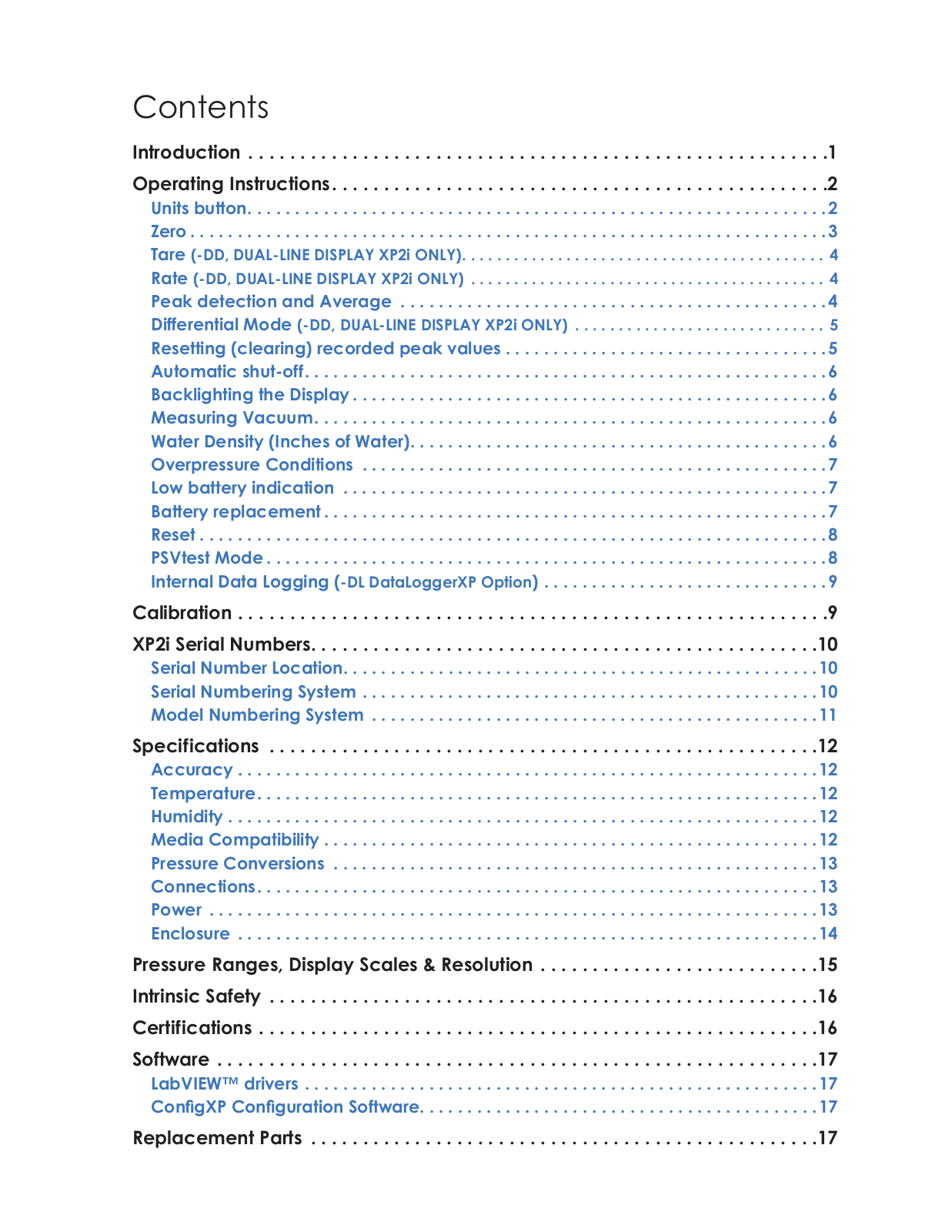
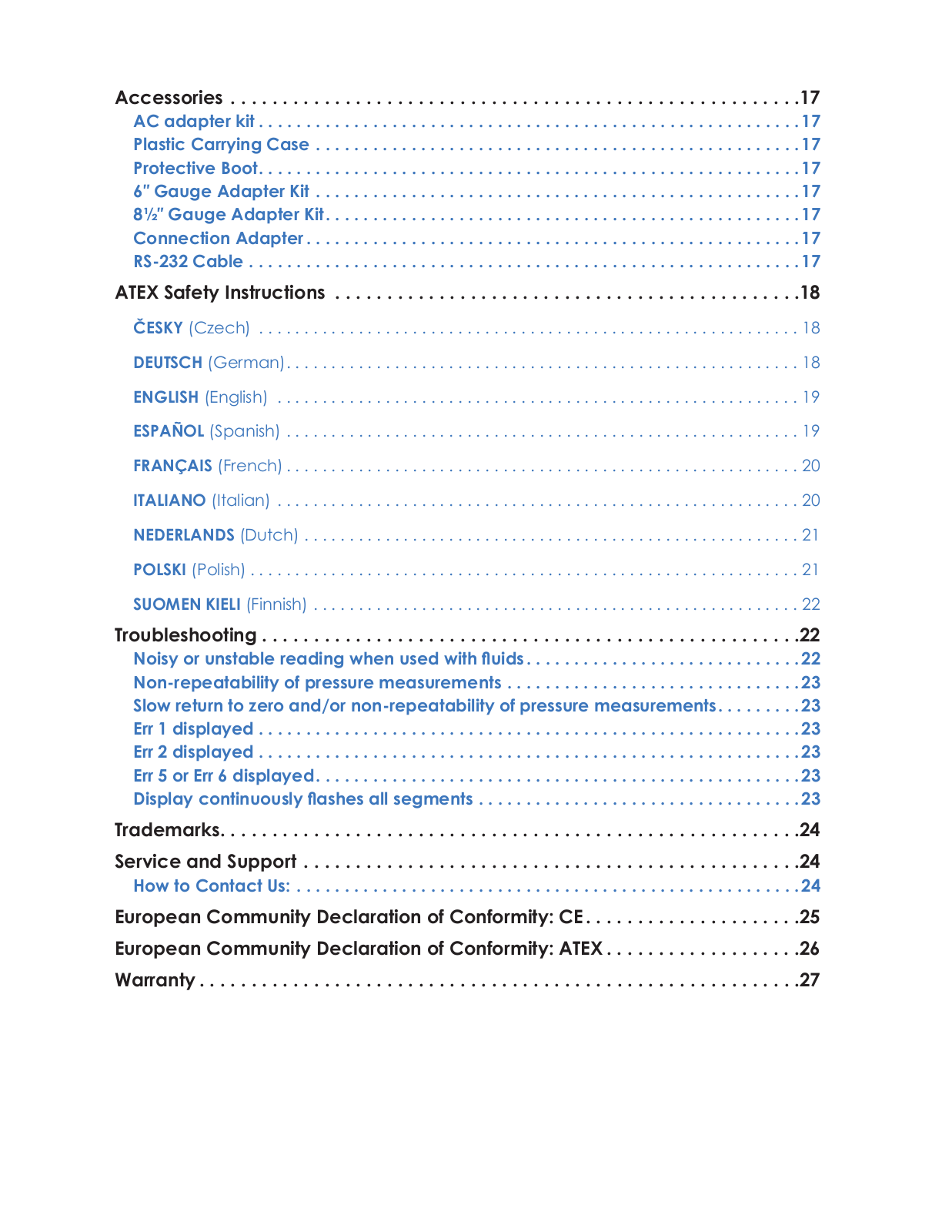
Table of contents
Loading...
Crystal XP2i Instruction Manual
...
Crystal Instruction Manual
Download
Specifications and Main Features
Frequently Asked Questions
User Manual
Download
Page 1
Page 2
Page 3
Page 4
Page 5
Page 6
Page 7
Page 8
Page 9
Page 10
Page 11
Page 12
Page 13
Page 14
Page 15
Page 16
Page 17
Page 18
Page 19
Page 20
Page 21
Page 22
Page 23
Page 24
Page 25
Page 26
Page 27
Page 28
Page 29
Page 30
Page 31
Page 32
Loading...
+
hidden pages
Unhide
You need points to download manuals.
1 point = 1 manual.
You can buy points or you can get point for every manual you upload.
Buy points
Upload your manuals