

Page 1
MultiCal Instruction Sheet
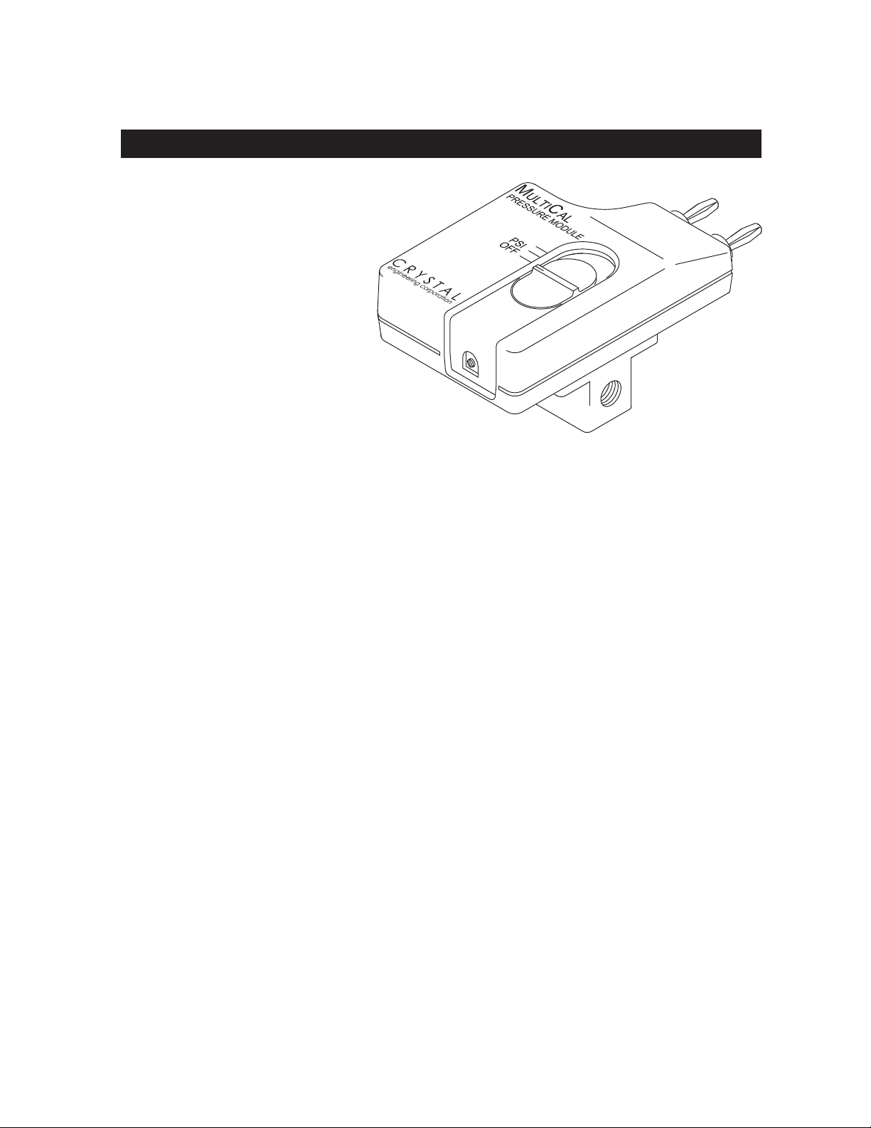
kPa/PSI Pressure Module
Introduction
MultiCal pressure modules are used to measure pneumatic or hydraulic pressures. They can
also be used to measure vacuum.
MultiCal modules don’t display
pressure, since they only have
an electrical output. Instead, the
modules convert pressure to
millivolts. Modules are used with
devices capable of measuring
DC millivolts, such as a digital
multimeters or oscilloscopes.
MultiCals are calibrated to convert
pressure units (for this model, inches kPa
or PSI) to 1 millivolt per pressure unit. Vacuum
readings will of course be negative.
Pressure is measured by connecting an appropriate fitting to one of the two 1/8″ female NPT
ports (plug any unused port). Any gas or liquid compatible with 316 stainless steel, PTFE
(polytetrafluoroethylene) impregnated hard anodized aluminum, and buna-n rubber, can be
applied to the module as the pressure source.
The three-position switch acts as a power switch as well as selecting kPa or PSI scaling
for the output. The OFF position is used to measure the internal battery condition via an
external multimeter.
MultiCal modules perform best when used with high accuracy multimeters. We recommend
meters manufactured by the Fluke Corporation, but MultiCals can be used with any meter
that has 10MΩ or greater input impedance, and (preferably) 4mm banana jacks on 19mm
(3/4″) centers.
When used with a high performance multimeter, the pressure adapter becomes more
than just a “digital pressure gauge”. By using the features built-in to the Fluke 87 for
example, the system becomes a datalogger capable of measuring and recording peak high,
peak low and average pressures.
This manual includes instructions for calibrating the module itself, but we also offer repair,
calibration/certification services. MultiCals are manufactured (and serviced) by a company
that only makes pressure measuring instruments. It’s the only thing we do and that’s why we
say: Pressure is Our Business!
C R Y S T A L
engineering corporation
PN: 1763 Rev C, 4/2004
Page 1 of 8
Page 2

PN: 1763 Rev C, 4/2004
Page 2 of 8
PRESSURE is Our BUSINESS
™
Operating Instructions
To ensure safe and accurate operation, please be familiar with the following operations and
functions.
WARNING:
Severe injury or damage can occur through improper use of pressure instruments!
Do not exceed recommended pressure limits of tubing and fittings. Be certain all pressure
connections are secured. Never disconnect pressure instrumentation without first relieving
system pressure.
CAUTION:
Never insert any object (other than a 1⁄8″ NPT fitting) into the inlet ports. The sensor
diaphragm is very thin and can be damaged or destroyed by solid or sharp objects. Clean
the sensor with appropriate solvents, only.
The internal pressure sensor measures the difference between atmospheric (barometric)
pressure, and the pressure (or vacuum) applied to the pressure port. The pressure being
measured can be either liquid or gaseous, providing it is compatible with the materials listed
in the specification section.
PTFE tape should be used with any fittings installed into either of the 1⁄8″ female NPT ports.
Two ports are provided so that additional tees should not be required. Plug any unused
ports.
MultiCals have been calibrated for use with meters that have 10MΩ input impedance, as do
most handheld meters, and some benchtop multimeters. If your meter has higher or lower
input impedance, add 0.1% to the specification of the MultiCal, or refer to the Calibration
section of this manual for other methods of eliminating the error introduced by an impedance
mismatch.
Pressure Measurement
Follow this procedure to correctly use the MultiCal pressure module.
1. Plug the MultiCal directly into the voltage input terminals of the multimeter or with the
patch cord set. The patch cord set consists of a 48″ cord with double banana plugs
on each end and a double banana jack splice. Plug the splice into the MultiCal and
the patch cord into the splice. Plug the other end of the patch cord into the multimeter.
Polarity is marked on the MultiCal and on the patch cord and splice.
2. Set the multimeter to the millivolt (DC) range.
3. Check the battery condition: With the MultiCal still in the OFF position, the
multimeter must indicate a minimum reading of 100 mV. Readings less than 100 mV
indicate the battery must be replaced. To be sure that your pressure measurements are
accurate, always check the battery condition first, and replace the battery if necessary.
4. Turn on the MultiCal by sliding the switch to the range you intend to use.
Page 3

PN: 1763 Rev C, 4/2004
Page 3 of 8
C R Y S T A L
engineering corporation
5. “Zero” the MultiCal. Without any pressure or vacuum applied to the module turn the
knob opposite the banana plugs until your meter reads precisely zero. Prior to taking
measurements, and recommended when changing scales, the module should be
“zeroed” at barometric pressure.
Most multimeters “forget” the “relative” setting when changing from mV to any other
scale, even just to Volts. Some meters autorange from mV to Volts and then lose the
“relative” value. In these cases the zero knob may be more convenient than the “relative”
button on the multi-meter.
The zero reading may also shift when the MultiCal is shifted from a vertical to a
horizontal orientation. This is due to the oil filling that transmits the pressure signal
from the stainless steel diaphragm to the silicon pressure sensor. The magnitude of the
shift is typically 0.07 kPa or less.
6. Apply pressure to the MultiCal. If the meter reads overrange, change the multimeter
range to DC volts (instead of mV). Note: The decimal place will be for volts. Multiply the
reading by 1000. For example, 0.200 V would be 200 kPa.
Battery Replacement
1. Set the power switch to the OFF position.
2. Disconnect the MultiCal from the multimeter and any pressure connections.
3. Turn the MultiCal so the power switch is facing down. Remove the single screw located
between the banana plugs.
4. Grasp the one case half in each hand. Pull the two halves apart, beginning at the end
with the banana plugs.
5. Remove and replace the battery.
6. Reassemble the MultiCal. To reassemble, mate the two case halves at the end opposite
the banana plugs, then “snap” the two halves together.
Page 4

PN: 1763 Rev C, 4/2004
Page 4 of 8
PRESSURE is Our BUSINESS
™
MultiCal Calibration
A calibration cycle of 1 year is recommended to maintain the MultiCal within specifications.
Table 1: Recommended Equipment
Instrument Minimum Specification Recommended Model
Pressure Standard ± 0.025% of Reading DH Instruments PPC2+
Digital Voltmeter
You do not need to use a reference multimeter, if the MultiCal will be used with only one
multimeter. In those cases, your overall accuracy may be better if it is calibrated as a set with
the matching multimeter.
The recommended Digital Voltmeter listed in Table 1 has 10MΩ input impedance - as
do many handheld multimeters. Your reference multimeter should have the same input
impedance as the multimeter(s) the module will be used with. In some cases this may mean
that the reference multimeter will need to have its input impedance lowered.
For example, a Fluke 8840A is an excellent benchtop meter, but it has an input impedance of
≥10,000MΩ. If the module will be normally used with a lower impedance meter, like a Fluke
87, which has an input impedance of 10MΩ, simply connect a 10MΩ resistor in parallel with
the input to the 8840A.
Procedure
1. Connect the MultiCal to the pressure calibration system and to the multimeter. Be sure
that the pressure calibration system and the connection to the MultiCal is leak free.
2. Allow the MultiCal to stabilize at room temperature, away from drafts, for at least 30
minutes before proceeding with calibration. Turn on the multimeter and allow it to warm
up per the multimeter operating instruction. Set the multimeter to the appropriate DC volt
or millivolt scale.
± 0.025% of Reading
10MΩ input impedance
Fluke 45
3. Verify the condition of the battery and replace the battery if necessary. Follow the Battery
Replacement procedure to disassemble the MultiCal, but do not remove the battery or
reassemble the MultiCal.
4. Set the switch on the MultiCal to the kPa position (switch in position closest to the
banana plugs). Allow the MultiCal to warm up for two minutes.
5. The Fine Zero potentiometer (R1) should be set to the center of its rotational range. To
center the Fine Zero, rotate the Fine Zero potentiometer fully clockwise until a “click” is
heard. Then rotate the FINE ZERO potentiometer counter-clockwise 7½ turns. Adjust
the COARSE ZERO pot until the output is as close to zero as possible. Trim in the final
reading to 0 mV ±0.01 mV with the FINE ZERO potentiometer.
Page 5

PN: 1763 Rev C, 4/2004
Page 5 of 8
C R Y S T A L
engineering corporation
6. Check the kPa pressure points shown on Table 2. Adjust R12 if necessary to bring the
FINE ZERO
kPa
PSI
COARSE ZERO
-
LINEARITY
R1
R12
R15
readings to within the tolerances shown on Table 2.
7. Set the switch on the MultiCal to the PSI position.
8. Test the MultiCal at the 30 PSI point. The reading should be within the tolerance shown in
Table 2. If not, adjust R15 until both points are within specification.
9. In the unlikely event that you are unable to adjust the MultiCal so that all of the points
meet the tolerances of Table 2, contact Customer Service for assistance. Do not readjust
linearity. The linearity adjustment is factory set and should never require readjustment,
unless the sensor is replaced.
Figure 1: Potentiometer Locations
Table 2: Readings in mV @ 23°C ±5°C
True Pressure Acceptable Output (mV)
100 kPa 99.92 to 100.07
200 kPa 199.87 to 200.12
30 PSI 29.98 to 30.03
Specifications
The following specifications apply at 23°C, ±5°C for 1 year after calibration, and when
used with measuring devices having 10MΩ input impedance, or shunted so that their input
impedance is 10MΩ. Also, the module must be "zeroed" prior to taking measurements to
achieve the pressure specifications.
Page 6

PN: 1763 Rev C, 4/2004
Page 6 of 8
PRESSURE is Our BUSINESS
™
Pressure
EC Declaration of Conformity
I/We
Crystal Engineering Corporation
of
720 Aerovista Place, Suite B
San Luis Obispo, CA, 93401
USA
declare that
Pressure Module
MultiCal Series (All Versions)
In accordance with the following directives
89/336/EEC The Electromagnetic Compatibility Directive
and its amending directives
has been designed and manufactured to the following specifications
EN 61326-1:2002 Conducted Emissions Class A N/A
EN 61326-1:2002 Radiated Emissions Class A Pass
EN 61000-3-2:1995 Current Harmonic Emissions Class A N/A
EN 61000-3-3:1995 Voltage Variations & Flicker N/A N/A
EN 61000-4-2:2002 Electrostatic Discharge
Pass
EN 61000-4-3:2002
Radiated EM Field
Pass
EN 61000-4-4:2002
Electrical Fast Transient/Burst
N/A
EN 61000-4-5:2002
Surge Immunity
N/A
EN 61000-4-6:1994
RF Conducted Disturbances
N/A
EN 61000-4-8:1994
Power Magnetic Field
N/A
EN 61000-4-11:1994
Voltage Dips and Interruptions
N/A
Note: Product is battery operated.
I hereby declare that the equipment named above has been designed to comply with the
relevant sections of the above referenced specifications. The unit complies with all essential
requirements of the Directives
David K. Porter, P.E.
(NAME OF AUTHORIZED PERSON)
Director of Engineering
(TITLE OF AUTHORIZED PERSON)
16 July 2003
(SIGNATURE OF THE AUTHORIZED PERSON) (DATE OF ISSUE)
Range Accuracy
0 to 200 kPa ±(0.05% of Reading + 0.1″H2O)
0 to 30 PSI ±(0.05% of Reading + 0.01PSI)
30 to 50 PSI ±(0.25% of Reading)
0 to -100kPa ±(0.5% of Reading + 0.14 kPa)
0 to -14.7 PSI ±(0.25% of Reading), typical
Maximum Working Pressure: 100 PSI
Burst Pressure: 500 PSI
Wetted Materials: 316 Stainless Steel, PTFE impregnated hard
anodized aluminum, and buna-n rubber.
Unless otherwise specified at time of purchase: 1 PSI = 27.6806″H2O (water at 4°C)
Operating Environment
Temperature Range Humidity
-10 to 10°C Uncontrolled Humidity
10 to 30°C 0 to 95% Relative Humidity
30 to 40°C 0 to 75% Relative Humidity
40 to 50°C 0 to 45% Relative Humidity
50 to 55°C 0 to 35% Relative Humidity
Temperature Derating
Add to Basic Accuracy Specification. °C = ambient temperature.
Temperature Range Derating
28 to 55°C (0.016%/°C) x (°C - 28°C)
18 to 28°C No Derating
0 to 18°C (0.048%/°C) x (18° - °C)
-10 to 0°C (0.264%/°C) x (9° - °C)
General Specifications
Weight 164 grams (5.8 oz.) w/battery
Overall length 118mm (45/8″)
Battery NEDA#1604, 6F22, 006P
Battery Life 400 Hours typ. w/alkaline battery
Output 1mV/unit into 10MΩ load
Storage -51°C to 71°C
Page 7

PN: 1763 Rev C, 4/2004
Page 7 of 8
C R Y S T A L
engineering corporation
European Community Declaration of Conformity
EC Declaration of Conformity
I/We
Crystal Engineering Corporation
of
720 Aerovista Place, Suite B
San Luis Obispo, CA, 93401
USA
declare that
Pressure Module
MultiCal Series (All Versions)
In accordance with the following directives
89/336/EEC The Electromagnetic Compatibility Directive
and its amending directives
has been designed and manufactured to the following specifications
EN 61326-1:2002 Conducted Emissions Class A N/A
EN 61326-1:2002 Radiated Emissions Class A Pass
EN 61000-3-2:1995 Current Harmonic Emissions Class A N/A
EN 61000-3-3:1995 Voltage Variations & Flicker N/A N/A
EN 61000-4-2:2002 Electrostatic Discharge
Pass
EN 61000-4-3:2002
Radiated EM Field
Pass
EN 61000-4-4:2002
Electrical Fast Transient/Burst
N/A
EN 61000-4-5:2002
Surge Immunity
N/A
EN 61000-4-6:1994
RF Conducted Disturbances
N/A
EN 61000-4-8:1994
Power Magnetic Field
N/A
EN 61000-4-11:1994
Voltage Dips and Interruptions
N/A
Note: Product is battery operated.
I hereby declare that the equipment named above has been designed to comply with the
relevant sections of the above referenced specifications. The unit complies with all essential
requirements of the Directives
David K. Porter, P.E.
(NAME OF AUTHORIZED PERSON)
Director of Engineering
(TITLE OF AUTHORIZED PERSON)
16 July 2003
(SIGNATURE OF THE AUTHORIZED PERSON) (DATE OF ISSUE)
Page 8

Warranty
Crystal Engineering Corporation warrants MultiCals to be free from defects in material and
workmanship under normal use and service for one (1) year from date of purchase to the
original purchaser. It does not apply to batteries or when the product has been misused,
altered or damaged by accident or abnormal conditions of operation.
Crystal Engineering will, at our option, repair or replace the defective device free of charge
and the device will be returned, transportation prepaid. However, if we determine the failure
was caused by misuse, alteration, accident or abnormal condition of operation, you will be
billed for the repair.
CRYSTAL ENGINEERING CORPORATION MAKES NO WARRANTY OTHER THAN
THE LIMITED WARRANTY STATED ABOVE. ALL WARRANTIES, INCLUDING IMPLIED
WARRANTIES OF MERCHANTABILITY OR FITNESS FOR ANY PARTICULAR PURPOSE,
ARE LIMITED TO A PERIOD OF ONE (1) YEAR FROM THE DATE OF PURCHASE.
CRYSTAL ENGINEERING SHALL NOT BE LIABLE FOR ANY SPECIAL, INCIDENTAL OR
CONSEQUENTIAL DAMAGES, WHETHER IN CONTRACT, TORT OR OTHERWISE.
Note (USA only): Some states do not allow limitations of implied warranties or the exclusion
of incidental or consequential damages, so the above limitations or exclusions may not apply
to you. This warranty gives you specific legal rights and you may have other rights which
vary from state to state.
How to Contact Us:
Phone. . . . . . . . (805) 595-5477
Toll-Free . . . . . (800) 444-1850
Fax. . . . . . . . . . (805) 595-5466
Email . . . . . . . . service@crystalengineering.net
Web . . . . . . . . . www.crystalengineering.net
If calling, have ready the model number, serial number, date of purchase and reason for
return. You will receive instructions for returning the device to Crystal Engineering.
Send your comments to: feedback@crystalengineering.net
© 2004, Crystal Engineering Corporation
720 Aerovista Place, Suite B
San Luis Obispo, CA 93401-8701
PN: 1763 Rev C, 4/2004
Page 8 of 8
PRESSURE is Our BUSINESS
™
 Loading...