


GaugeCalxp
Operator Instructions
™
PRESSURE COMPARATOR
10000 PSI–700bar
C R Y S T A L
engineering corporation
Page 2 • GaugeCalXP Operator Instructions
Introduction
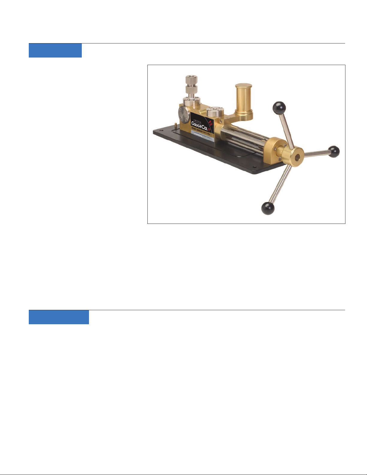
Thank you for purchasing a GaugeCalXP™
Pressure Calibrator from Crystal Engineer-
ing. The GaugeCalXP is a self contained,
precision hydraulic pressure generator
intended for the calibration of pressure
gauges rated up to 700 bar or 10,000 PSI.
Two pressure ports are provided. Connect
a reference grade gauge on one port (we
recommend an XP2i from Crystal Engineer-
ing) and the gauge to be tested on the
second port. Rotate the handle clockwise
until the desired pressure is generated.
Then, compare the displayed pressure val-
ues between the reference gauge and the
gauge under test.
PRESSURE is Our BUSINESS
®
Pressure can be set very quickly and pre-
cisely. Gauges can be calibrated in less than ten minutes (5 to 10 test points, increasing and decreasing pressure) if you
follow the method outlined in this manual. The comparator can be lled with your choice of uid: water, oil or isopropyl
alcohol.
The GaugeCalXP is much, much faster to use than a deadweight tester, and it’s also faster than most automated pressure
controllers, but it costs much less than either. It’s so quick and easy to use, it’s ideal to calibrate those low cost gauges that
are often overlooked for ISO9000 compliance. Please spend a few minutes to read this manual, and learn how you can
get the most benet from your GaugeCalXP.
Specifications
Performance
Maximum Pressure . . . . . . . . . . . . . . .10,000 PSI / 700 BAR
Minimum Pressure . . . . . . . . . . . . . . . . . . . . . . 5 PSI / 0.5 BAR
Burst Pressure . . . . . . . . . . . . . . . . . >20,000 PSI / 1400 BAR
Materials
Ram/Adapters . . . . . . . . . . . . . . . . . . . . . . . . . . . . . . . . . . 316SS
Body . . . . . . . . . . . . . . . . . . . . . . . . . . . . . . . . . . . . . . . Aluminum
Seals . . . . . . . . . . . . . . . . . . . . . . . . . . . . . . . . . . Buna N (Nitrile)
Test Media. . . . . . . . . . . . . Water, Oil, or Isopropyl Alcohol
C R Y S T A L
engineering corporation
Dimensions
Width (of base) . . . . . . . . . . . . . . . . . . . . . . . . 175mm (6.88”)
Length (of base) . . . . . . . . . . . . . . . . . . . . . . 429mm (16.88”)
Length (overall) . . . . . . . . . . . . . . . . . . . . . . . 495mm (19.50”)
Weight . . . . . . . . . . . . . . . . . . . . . . . . . . . . . . . . 6.4kg (14.2 lbs)
Accessories (included)
Adapters . . . . . . . . . . . . . . . . . . . . . . . 1/4” and 1/2” NPT std.
Wrenches . . . . . . . . . . . . . . . . . . . . . . . . . . . . . . . . . . . . . . . . . . . 2
Shipping Information
Shipping Weight . . . . . . . . . . . . . . . . . . . . . . . . . 8.6kg (19 lbs)
Dimensions . . . . . . . . . . . . . . .559mm x 305mm x 229mm
(22.0” x 12.0” x 9.0”)
GaugeCalXP Operator Instructions • Page 3
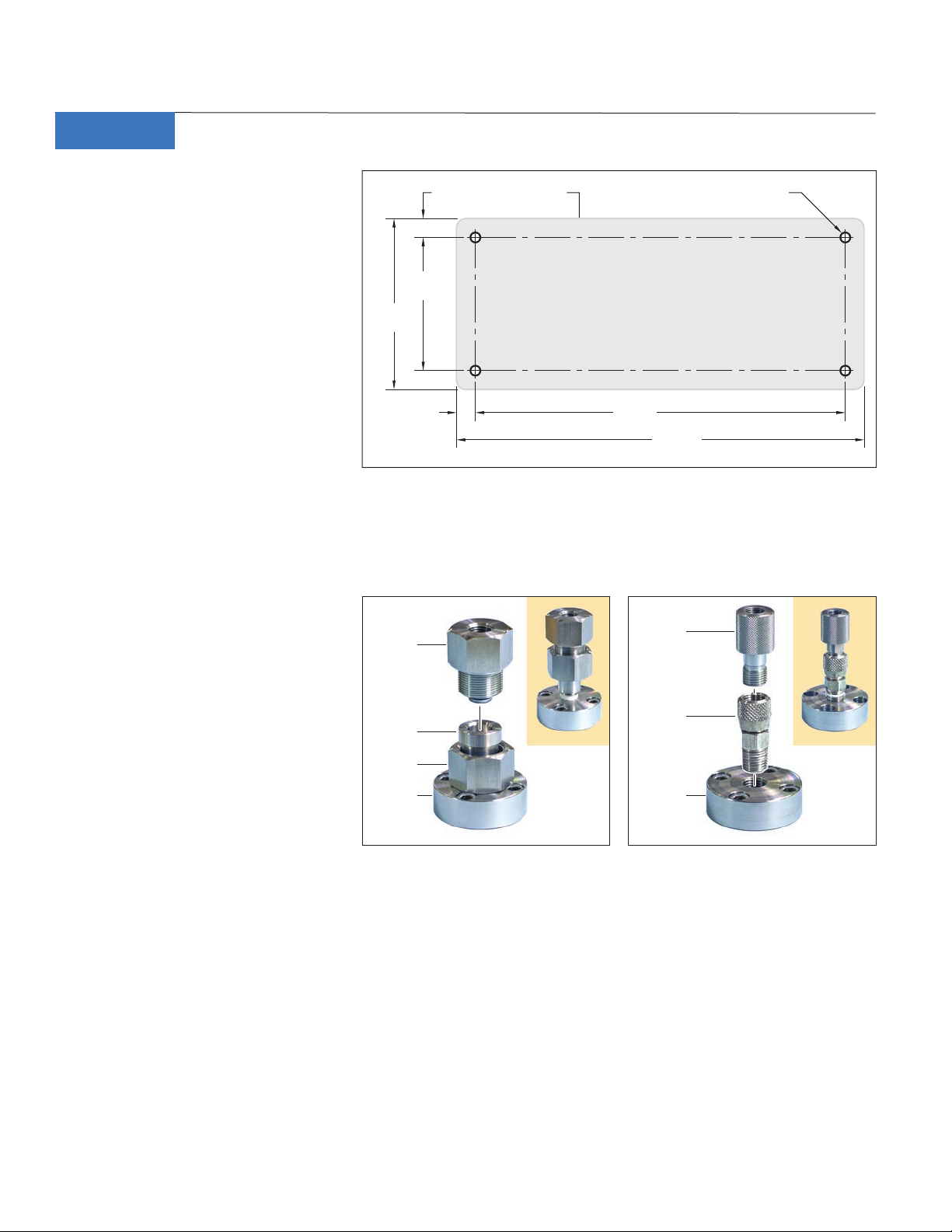
Baseplate16.25mm
[0.64”]
19.4mm
[0.76”]
O/ 10mm [O/ 0.39”], 4 places
Maximum bolt size, 8mm or [5/16”]
174.9mm
[6.88”]
142mm
[5.60”]
390mm
[15.35”]
428.8mm
[16.88”]
Gauge
Adapter
Flange
Stem
Stem Nut
Flange
Base
Quick-
Connect
Gauge
Adapter
Stem
Adapter
Flange
Base
Operation
For safe and reliable operation of your
GaugeCalXP Pressure Comparator, please
spend a few minutes reading the follow-
ing instructions.
1 Mount the comparator to your bench
or table: At higher pressures the force
required to rotate the handle may
cause the base of the comparator to
lift. We recommend that the compara-
tor be bolted to your bench or table.
Refer to Figure 1 for the hole pattern
and suggested bolt sizes.
2 Install the ange stem or stem adapters:
There are two (2) stainless steel ange bases. Each base has a 1/4” female (tapered) NPT thread. These bases are in-
tended to have either a ange stem (Figure 2) or stem adapter (Figure 3) for quick connectors installed. It is possible
to install an XP2i reference gauge directly into the base, but this is practical if only one XP2i will be regularly used
with the comparator.
Figure 1. GaugeCalXP Pressure Comparator mounting hole pattern.
One ange stem is supplied with the
comparator, and installed into a base
ange. If testing is limited to 5000 PSI
(350 bar) or less, quick connect ttings
that eliminate wrenches, thread tape or
sealant, may be used. Use PTFE thread
tape when installing either the ange
stem(s) or the stem adapter(s) into the
ange base(s).
3 Fill the reservoir: The reservoir holds
Figure 2. Two stainless steel gauge adapters are supplied with
the GaugeCalXP Pressure Comparator.
Figure 3. O ptional quick-connect gauge adapters allow quick
interchange of gauges without the need for sealing tape or
wrenches.
the test uid that lls the system each
time you test a gauge. The test uid can be either water, lightweight hydraulic oil, or isopropyl alcohol. Wind the han-
dle fully counter-clockwise, then clockwise for at least 10 turns (this prevents uid ow through the comparator and
potential uid spillage). Then ll the reservoir with test uid to within 6mm (1/4”) of the top. Turn the handle counter-
clockwise until you see the uid level in the reservoir drop. This lls the system with uid and removes any trapped
air bubbles. The reservoir cap has an o-ring to allow the GaugeCalXP to be transported with the test uids in place.
Due to the sealing capabilities of the cap, it must be removed or ajar during testing to allow proper equalization of the
system.
C R Y S T A L
engineering corporation

Page 4 • GaugeCalXP Operator Instructions
XP2i Digital Test gauge
mounted with the supplied
NPT gauge adapter.
Analog gauge to be tested
mounted with a quick-connect
gauge adapter.
4 Install the digital gauge: Use a ¼” fe-
male NPT gauge adapter (Figure 4).
If you are using the ange stem, ap-
ply PTFE thread tape to the pressure
gauge threads, then screw the gauge
into the adapter (PN: 3116). Be sure to
use wrenches on both the tting AND
the gauge when tightening the tting.
CAUTION: Never use wrenches when
connecting the gauge adapter to the
stem adapter tting—hand tight is sucient to insure a leak free connection. The
wrenches are intended to help separate
the gauge adapter from the stem adapter
tting, if necessary.
PRESSURE is Our BUSINESS
®
If you are using the quick connect
adapter (PN 3126), just screw it onto
the gauge, nger tight, then onto the stem adapter, also nger tight. Although wrench ats are provided on the quick
connect adapter, these are intended only to help remove the adapter.
CAUTION: Never use a wrench to tighten a quick connect adapter.
5 Install the gauge to be tested: As with the digital gauge, choose the appropriate adapter, either the quick connect or
regular gauge adapter (Figure 4).
6 Remove any remaining air from the system: Each time you install a new gauge, air bubbles may be introduced
into the Comparator and cause problems with calibration. Check again that the reservoir is full, then turn the handle
counter-clockwise until it stops at the full out position. If air bubbles are present in the system, the test uid level in the
reservoir will drop as it ows into the Comparator. If necessary, repeat this step until all trapped air has been removed.
Another way to remove air bubbles is to tilt the comparator. Wind the handle fully counter-clockwise, then lift the back
of the comparator. Any remaining bubbles will come out the back ange adapter.
7 Set up the digital pressure gauge: Turn on the XP2i, and then select the pressure units required for the gauge to
be tested—kg/cm2, bar, kPa, or PSI. (Refer to the documentation you received with your Crystal Engineering XP2i for
detailed operating instructions.)
8 Start the test: We recommend that you exercise the gauges by applying the full scale pressure of the gauge being
tested, one or more times. To apply pressure to the gauges, wind the handle in a clockwise direction. (To decrease
pressure to the gauges, wind the handle in a counter-clockwise direction). After decreasing the pressure to zero, re-
check the uid level in the reservoir, and rezero the XP2i, if necessary. You will notice that the application of pressure is
non-linear, therefore pressure increases at a more rapid rate at higher pressures.
Figure 4. The GaugeCalXP Pressure Comparator can be congured with an XP2i digital test gauge and a gauge to be tested, in either
of the two ports.
C R Y S T A L
engineering corporation

GaugeCalXP Operator Instructions • Page 5
bar
4
2 8
6
0 10
C R Y S T A L
engineering corporation
300 PSI
Note: If you cannot generate the desired pressure it is because one of two reasons: Either the system has too much air
in it, or the volume being pressurized is too large. Repeat step 6 to bleed the system and start again. If this does not
solve the problem, the volume is too large, and an auxiliary hydraulic pump is required.
9 Compare pressure readings: Wind the handle clockwise on the comparator so that the needle on the gauge being
tested is centered on the rst major graduation mark (or rst calibration point). These major marks are usually placed
at 10% or 20% increments of the full scale of gauge being tested. Hold the pressure for 15 seconds, then compare the
pressure on the gauge to be tested to the pressure displayed on the XP2i digital gauge, and record the reading on the
XP2i (Figure 5).
Normally, pressure will drop at rst,
as each ascending pressure point is
reached. This is due to the residual,
trapped gas, rst heated by compres-
sion, then cooled, so that the com-
pressed gas is at the same temperature
as the ambient environment. An equal
and opposite eect happens when re-
ducing pressure—the pressure will rise
as each new lower pressure is achieved.
Waiting for these thermal eects to sta-
bilize can add a lot of time to the cali-
bration.
10 Quick test method: An alternative
method eliminates the time required
to wait for thermal pressure stability. Start by setting the XP2i into the Peak “Hi” mode and clearing any stored peak
value. As above, increase pressure to the rst major graduation on the gauge (or calibration point), but increase pres-
sure slowly, so that you don’t overshoot the mark (or point). The pressure recorded on the XP2i will be the pressure
that was applied when the gauge was on the mark—even if actual pressure drops. Just record the reading from the
XP2i and continue to the next test point or mark. If you are also checking the gauge for hysteresis, the procedure is the
same, except that you start at full scale and set the XP2i to indicate the Peak “Lo”, and then clear the peaks at full scale
pressure. The XP2i will record the descending points in the same way.
Eliminating the time required to wait for thermal equilibrium, signicantly shortens the amount of time it takes to
calibrate a gauge.
Note: Below the rear gauge ange base of the Pressure Comparator are ports for an optional Fine Adjust accessory.
The Fine Adjust can be mounted on either side of the manifold block at the rear of the comparator. While the Fine
Adjust accessory is helpful for ne pressure adjustments, it is not necessary for general calibration. The Fine Adjust Kit
(P/N 3205) can be ordered directly from Crystal Engineering.
Figure 5. Checking the accuracy of an analog pressure gauge against the display of the XP2i digital pressure gauge.
C R Y S T A L
engineering corporation

Page 6 • GaugeCalXP Operator Instructions
Up to 10,000 PSI-700 bar
Kit p/n Individual Component p/n
GaugeCalXP Pressure Comparator
Fine Adjust Kit for GaugeCalXP
Rebuild Kit for GaugeCalXP
Rolling Carry Case Kit for GaugeCalXP
1
/8" Female NPT Gauge Adapter
1
/4" Female NPT Gauge Adapter (included)
1
/2" Female NPT Gauge Adapter (included)
1
/4" BSPP Gauge Adapter
1
/2" BSPP Gauge Adapter
3
/8" BSPP Gauge Adapter
NPT Quick-Connect Gauge Adapter Kit
Quick-Connect 1/8" Female NPT Gauge Adapter
Quick-Connect 1/4" Female NPT Gauge Adapter
Quick-Connect 1/2" Female NPT Gauge Adapter
1
/4" Male NPT Stem Adapter
BSPP Quick-Connect Gauge Adapter Kit
1
/4" Male NPT Stem Adapter
Quick-Connect 1/8" BSPP Gauge Adapter
Quick-Connect 1/4" BSPP Gauge Adapter
Quick-Connect 3/8" BSPP Gauge Adapter
Quick-Connect 1/2" BSPP Gauge Adapter
PTFE Thread Tape, 6mm (1/4") wide
3134
3116
3117
3137
3135
3136
3125
3126
3127
3254
3254
3184
3185
3186
3187
1810
3205
3143
3395
3183
3188
Up to 5,000 PSI-350 bar
Optional Accessories
PRESSURE is Our BUSINESS
®
C R Y S T A L
engineering corporation

GaugeCalXP Operator Instructions • Page 7
Warranty
Crystal Engineering Corporation warrants the GaugeCalXP Pressure Comparator to be free from defects in material and
workmanship under normal use and service for one (1) year from date of purchase to the original purchaser. It does not
apply when the product has been misused, altered, or damaged by accident, or abnormal conditions of operation.
For in (or out) of warranty service, we can be reached at:
Phone . . . . . . . . . . . . . . . . . . . . . . . . . . . . . . . . . (805) 595-5477
Email . . . . . . . . . . . . . . . . . service@crystalengineering.net
Web . . . . . . . . . . . . . . . . . . . . . www.crystalengineering.net
If calling, have ready the model number, serial number, date of purchase, and reason for return. You will receive instruc-
tions for returning the device to Crystal Engineering.
Crystal Engineering will, at our option, repair or replace the defective device free of charge, and the device will be re-
turned, transportation prepaid. However, if we determine the failure was caused by misuse, alteration, accident, or abnor-
mal condition of operation, you will be billed for the repair.
CRYSTAL ENGINEERING CORPORATION MAKES NO WARRANTY OTHER THAN THE LIMITED WAR-
RANTY STATED ABOVE. ALL WARRANTIES, INCLUDING IMPLIED WARRANTIES OF MERCHANT-
ABILITY OR FITNESS FOR ANY PARTICULAR PURPOSE, ARE LIMITED TO A PERIOD OF ONE (1) YEAR
FROM THE DATE OF PURCHASE. CRYSTAL ENGINEERING SHALL NOT BE LIABLE FOR ANY SPECIAL,
INCIDENTAL, OR CONSEQUENTIAL DAMAGES, WHETHER IN CONTRACT, TORT, OR OTHERWISE.
Note (USA only): Some states do not allow limitations of implied warranties or the exclusion of incidental or consequen-
tial damages, so the above limitations or exclusions may not apply to you. This warranty gives you specic legal rights and
you may have other rights which vary from state to state.
Phone (Toll Free) . . . . . . . . . . . . . . . . . . . . . . . (800) 444-1850
FAX . . . . . . . . . . . . . . . . . . . . . . . . . . . . . . . . . . . (805) 595-5466
C R Y S T A L
engineering corporation

C R Y S T A L
engineering corporation
© 2006 C rysta l Enginee ring Corpor at ion
708 Fiero Lane, Su ite 9, San Luis Ob ispo, Cali forn ia 9 34 01-8701
PN: 317 1—Re v C
 Loading...