

Page 1

Operation ManualGaugeCalXP
Page 2

Contents
Overview ................................................................ 1
Introduction ..............................................................1
Operation ............................................................... 2
Specifications .......................................................... 7
Performance ..............................................................7
Materials ..................................................................7
Dimensions ...............................................................7
Accessories ................................................................7
Shipping Information ......................................................7
Certification ...............................................................7
Ordering Information ................................................8
Pressure Comparator ......................................................8
Fitting Kits ................................................................8
Support .................................................................. 9
Contact Us ................................................................9
Repair. . . . . . . . . . . . . . . . . . . . . . . . . . . . . . . . . . . . . . . . . . . . . . . . . . . . . . . . . . . . . . . . . . . . .9
Warranty ..................................................................9
Page 3

Overview
IntroductIon
Thank you for purchasing a GaugeCalXP™ Pressure Calibrator from Crystal Engineering. The GaugeCalXP is a self-contained, precision hydraulic pressure
comparator intended for the calibration of pressure gauges rated up to 700 bar or 10 000 PSI. You may fill the GaugeCalXP with your choice of water or oil.
—
Using this comparator for calibration is much faster than deadweight testers and most automated pressure controllers. The GaugeCalXP is so quick and easy
to use, it is ideal for calibrating those low cost gauges that are often overlooked for ISO9000 compliance.
In fact, you can calibrate most gauges, transmitters, pressure safety valves, sensors, and switches in less than ten minutes (5 to 10 test points, increasing and
decreasing pressure) using the methods described in this manual.
Spend a few minutes to read this manual and learn how you can get the most benefit from your GaugeCalXP.
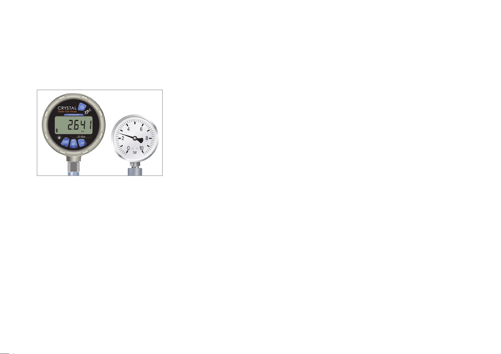
Note: We recommend using one of these three Crystal reference gauges with the GaugeCalXP.
Overview 1
XP2i Digital Test Gauge nVision Reference Recorder 30 Series Pressure Calibrator
GaugeCalXP Operation Manual
Page 4

Operation
Follow these instructions for safe and reliable operation of your GaugeCalXP Pressure Comparator.
Operation 2
1 Mount the c
174. 9
(6.88)
Baseplate dimensions and suggested bolt sizes
omparator to your bench or table: At higher pressures the force required to rotate the handle may cause the base of the comparator to lift.
All dimensions in mm (in)
142
(5.60)
19.4
(0.76)
16. 25
(0.34)
Baseplate
Ø 10.00 (Ø 0.39), 4 places
Maximum bolt size: 8mm or 5/16"
390
(15.3 5)
428. 8
(16. 88)
2 Install the CPF-compatible ttings and any applicable adapters:
Crystal Pressure Fittings (CPF) simplify your connections and create fi nger-tight, leak-free connections up to 10 000 PSI/700 bar/70MPa working pressure.
No sealing tape is required. See the diagram below, or visit the website, for more information on CPF.
our GaugeCalXP is fi tted with a CPF base (7/16-20 MP) and will connect with the two included CPF male fi ttings (MPM-MPM) and two included 1/4" female
Y
fi ttings (MPF-1/4FPT). Should you have a need for additional fi ttings, visit crystalengineering.net or contact your Crystal Distributor. Refer to the diagram
ollowing page for connection information.
on the f
Finger-tight seal uses a
Viton 90 o-ring for a seal up to
10 000 PSI/ 700 bar/ 70MPa
(-20 to 50oC)
point of conta ct
Wrench-tight creates a
metal/metal seal up to
10 000 PSI/ 700 bar/ 70MPa
(-40 to 150oC)
GaugeCalXP Operation Manual
Page 5
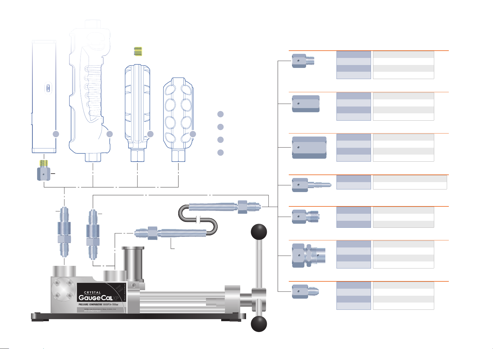
T
GaugeCalXP Connection Diagram
Operation 3
MPM-MPM
1
MPF-1/8MPTMPF-1/8MP
2
MPM-MPM
Denotes area where thread-sealing tape is required.
(CPF & Quick-Test connections
3
do not require thread-sealing tape.)
1
30 Series
2
nVision
4
3
XP2i
4
m1
NPT MALE
NPT FEMALE
BSP
TRANSMITTER
TUBE
MPF-1/8QTM 1/8" Quick Test NPT Male
MPF-1/8MPT 1/8" NPT Male
MPF-1/4QTM 1/4" Quick Test NPT Male
MPF-1/4MPT 1/4" NPT Male
Additional NPT sizes available in non-CPF MP adapters
MPF-1/8QTF 1/8" Quick Test NPT Female
MPF-1/4QTF 1/4" Quick Test NPT Female
MPF-1/4FPT 1/4" NPT Female
MPF-1/2QTF 1/2" Quick Test NPT Female
Additional NPT sizes available in non-CPF MP adapters
MPF-1/8BSPF G 1/8" Female
MPF-1/4BSPF G 1/4" Female
MPF-3/8BSPF G 3/8" Female
MPF-1/2BSPF G 1/2" Female
MPF-5/16TRM for Foxboro, Rosemount, & Yokogawa
MPF-1/4TRM for Honeywell
MPF-1/4TBM 1/4" Tube Male
MPF-3/8TBM 3/8" Tube Male
MPF-1/2TBM 1/2" Tube Male
CPF
MPH-XX
ADDITIONAL
MPF-MPF Female to Female
MPF-MPFTU T-Union (Female)
MPF-MPFBULK Bulkhead (Female to Female)
MPF-CAP Cap
MPF-M20QTF M20 x 1.5 Quick Test Female
MPF-M20X1.5F M20 x 1.5 Female
MPF-QCN Quick-Connect Nut
MPF-AN4M AN4 Male
GaugeCalXP Operation Manual
Page 6

3 Fill the reservoir: The reservoir holds the test fl uid that fi lls the system each time you test a gauge. The test fl uid can be either water or lightweight oil. Wind
the handle fully counter-clockwise, fi ll the reservoir until it is 25% full. Lift the back of the comparator six inches and tap on the side. The internal trapped air
will be removed. The reservoir cap has an o-ring to allow the GaugeCalXP to be transported with the test fl uids in place.
Operation 4
Note: Due to the sealing capabilities of the cap, it must be removed or ajar during operation to allow proper equalization of the syst
4 I
nstall the gauges:
fi tting directly to reference gauges equipped with a CPF female connection or attach an appropriate adapter. Repeat for the device under test.
The GaugeCalXP Pressure Comparator can be confi gured with a Crystal reference gauge (in this example, an XP2i) and a gauge to be tested in either of the two ports.
The above example also has the optional Fine Adjust and 1/4 female NPT Quick Test adapter installed.
Note: We recommend installing the Crystal reference in the rear port and the device under test in the front port of the GaugeCalXP.
5 If you are using CPF quick test fi
Although wrench fl ats are provided on the quick test fi tting, these are only intended to help remove the adapter.
CAUTION: Never use a wrench to tighten a quick connect adapter.
!
6 Slowly turn the handle clockwise until the fl
reference.
Slowly turn the handle of the GaugeCalXP clockwise until the fl uid is visible at the top of the MPM-MPM fi tting. Connect the MPM-MPM
ttings (MPF-1/4QTF) screw them onto the installed MPM-MPM fi ttings, fi nger-tight.
uid is visible at the same level as the MPF-1/4QTF o-ring, then attach your device under test. Repeat for the
em.
7 Turn the handle counter clockwise until it stops in the fully vented position.
8
Set up the Crystal reference gauge: Turn on the Crystal reference gauge, and then select the pressure units required for the gauge to be tested. (For de-
tailed operating instructions, refer to the documentation you received with your Crystal Engineering reference.)
9 Press the
(zero) button on your Crystal reference gauge.
GaugeCalXP Operation Manual
Page 7
10 Start the test: We recommend that you exercise the gauges by applying the full scale pressure of the gauge being tested, one or more times. To apply
pressure to the gauges, wind the handle in a clockwise direction. To decrease pressure to the gauges, wind the handle in a counter-clockwise direction.
After decreasing the pressure to zero, recheck the fl uid level in the reservoir, and rezero the Crystal reference gauge, if necessary. You will notice that the
application of pressure is non-linear, therefore pressure increases at a more rapid rate at higher pressures.
Operation 5
ompare pressure readings:
11 C
Wind the handle clockwise on the comparator so that the needle on the device under test is centered on the fi rst major gradua-
tion mark (or fi rst calibration point). These major marks are usually placed at 10% or 20% increments of the full scale of gauge being tested. Hold the pressure
for 15 seconds, then compare the pressure on the device under test to the pressure displayed on the Crystal reference gauge, and record the reading.
Checking the accuracy of an analog pressure gauge against the display of the Crystal reference gauge
Normally, pressure will drop at fi rst, as each ascending pressure point is reached. This is due to the residual, trapped gas, fi rst heated by compression, then
cooled, so that the compressed gas is at the same temperature as the ambient environment. An equal and opposite eff ect happens when reducing pres-
sure—the pressure will rise as each new lower pressure is achieved. Waiting for these thermal eff ects to stabilize can add a lot of time to the calibration.
12 Quick t
est method: An alternative method eliminates the time required to wait for thermal pressure stability. This method works with the Crystal XP2i and
nVision, but not with the 30 Series. Start by setting the Crystal reference gauge to detect peaks and clear any stored peak value. As above, increase pressure
to the fi rst major graduation on the device under test (or to the fi rst calibration point), but increase pressure slowly, so that you don’t overshoot the mark
(or point). The maximum pressure recorded on the Crystal reference gauge will be the pressure that was applied—even if actual pressure drops again im-
mediately. Just record the peak reading from the Crystal reference gauge and continue to the next test point or mark. If you are also checking the gauge for
hysteresis, the procedure is the same, except that you start at full scale and check the Crystal reference gauge for the Peak Lo. Eliminating the time required
to wait for thermal equilibrium, signifi cantly shortens the amount of time it takes to calibrate a gauge.
Note: The Fine Adjust option (PN 3205) may be mounted on either side of the GaugeCalXP. The ports for the Fine Adjust are located behind r
plates at the rear of the comparator.
Note: If you cannot generate the desired pressure it is for one of two reasons: Either the system has too much air in it, or the volume being pr
large. Use the procedure on the following page to remove more air from the system or to generate vacuum.
emovable side
essurized is too
GaugeCalXP Operation Manual
Page 8

Remove Air from the System or Generate Vacuum
WARNING: Do not use this procedure if the test device can be damaged by vacuum.
!
1 With the Crystal reference gauge in place, remove the device to be tested.
2 Install a short piece of hose going from the device test port to the top of the reservoir.
T
his is to return the fl uid expelled to the reservoir. If you do not have a short piece of hose please use paper towels or a shop rag to soak up the excess fl uid.
3 Rotate the screw handle fully clockwise.
M
ake sure the reservoir does not run out of fl uid while you do this.
4 Connect the device to be tested.
Operation 6
5 Fill the reservoir with fl
6 Rotate the screw handle fully counter-clockwise.
Obser
ve the reference gauge
vacuum at sea level for a device with a small volume.
7 As you reach the end of travel, and the comparator's piston reaches the fi
reservoir. Unless you are fi lling a very large device, the volume of fl uid in the reservoir should be suffi cient to completely fi ll the system. If not, repeat this
procedure, but be ready to fi ll the reservoir as it drops.
8 Before generating positive pressure with the comparator, refi
Note: If this procedure does not solve the problem, the volume is too large and an auxiliary hydraulic pump is required.
uid, almost to the top.
–
it should start indicating negative pressure as you rotate the screw handle. The GaugeCalXP can typically generate -12.5 PSI
ll point (about 1 cm from the end of travel), you will see the fl uid level drop in the
ll the reservoir.
GaugeCalXP Operation Manual
Page 9

Specifi cations
Specifi cations 7
PERFORMANCE
Hydraulic
—
Maximum Pressure . . . . . . . . . . . . . . 10 000 PSI / 700 bar
Minimum Pressure . . . . . . . . . . . . . . .5 PSI / 0.5 bar
Pneumatic Pressure
Maximum Pressure . . . . . . . . . . . . . . 400 inH2O / 995 mbar
Sensitivity (fi ne adjust option) . . . . 0.01 inH2O / 0.025 mbar
Burst Pressure
Pressure . . . . . . . . . . . . . . . . . . . . . . . . .>20 000 PSI / 1400 bar
MATERIALS
Ram/Adapters . . . . . . . . . . . . . . . . . . . 316SS
—
Body . . . . . . . . . . . . . . . . . . . . . . . . . . . . Aluminum
Seals . . . . . . . . . . . . . . . . . . . . . . . . . . . . Buna N (Nitrile)
Seals (Skydrol compatible) . . . . . . . EPDM
Test Media . . . . . . . . . . . . . . . . . . . . . . . Water, Oil, or Air
DIMENSIONS
Width (of base) . . . . . . . . . . . . . . . . . . 175mm (6.88 in)
—
Length (of base) . . . . . . . . . . . . . . . . . 429mm (16.88 in)
Length (overall) . . . . . . . . . . . . . . . . . . 495mm (19.50 in)
Weight . . . . . . . . . . . . . . . . . . . . . . . . . . 6.4kg (14.2 lbs)
Piston Stroke Volume . . . . . . . . . . . .1.8 in
Reservoir Volume . . . . . . . . . . . . . . . .3.35 in3 / 54.9 cm
ACCESSORIES
Included
—
Adapters . . . . . . . . . . . . . . . . . . . . . . . . (2) MPF-1/4FPT, (2) MPM-MPM
Wrenches. . . . . . . . . . . . . . . . . . . . . . . .2
SHIPPING INFORMATION
Shipping Weight . . . . . . . . . . . . . . . . . 8.6kg (19 lbs)
—
Dimensions . . . . . . . . . . . . . . . . . . . . . . 559mm x 305mm x 229mm
3
/ 29.5 cm
(22.0 in x 12.0 in x 9.0 in)
3
3
CERTIFICATION
The GaugeCalXP Pressure Comparator is approved for use as a portable test instrument for Marine use and complies with Det Norsjke Veritas’ Rules for
Classifi cation of Ships, High Speed & Light Craft, and Off shore Standards.
—
GaugeCalXP Operation Manual
Page 10
Ordering Information
PRESSURE COMPARATOR
P/N GAUGECALXP GaugeCalXP Pressure Comparator
—
Pressure Comparator, two CPF male-male ttings (P/N MPM-MPM), and two CPF 1/4" FNPT ttings (P/N MPF-1/4FPT ).
P/N GAUGECALXP-SKYDROL Skydrol-compatible GaugeCalXP Pressure Comparator
P
ressure Comparator (Skydrol compatible), Fine Adjust option, and rebuild kit.
Find individual Skydrol compatible ttings in our CPF tting
Options
P/N 3205 Fine Adjust kit
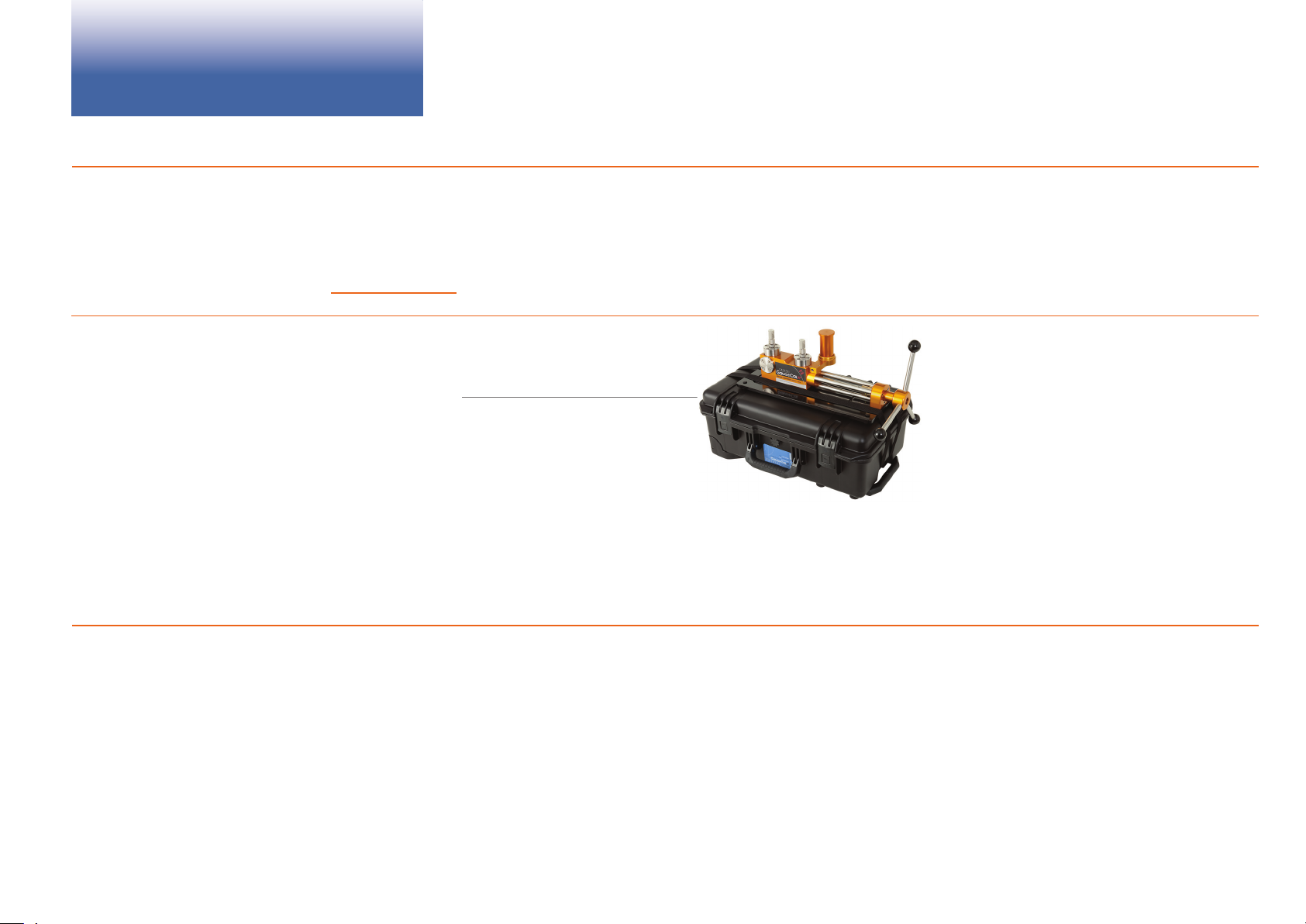
P/N 3395 Rolling Case for GaugeCalXP Rolling Case for GaugeCalXP
T
wo MPF-CAP ttings to prevent leaks while in transit, two hold-down straps, and uid bottle.
P/N FASTCALXP Gauge and Transmitter Calibration Software
F
astCalXP software, USB Security Key, CD, USB-RS232 adapter, and 30 series RS232 cable.
Datasheet.
Ordering Information 8
P/N 3327 USB Footswitch for FastCalXP
P/N 4138 Rebuild kit for GaugeCalXP
P/N 4158 Rebuild kit for GaugeCalXP-Skydrol
FITTING KITS
P/N 4012 GaugeCalXP CPF Upgrade—Upgrade previous versions of the GaugeCalXP to use the CPF tting system.
—
Includes (2) MPF-GC CPF ttings, (2) MPF-1/4FPT CPF ttings, and (2) MPM-MPM CPF ttings.
P/N 4013 Quick Test NPT Kit—A set of CPF conversion
Finger-tight to working pressure up to 10 000PSI / 700 bar.
Includes (1) MPF-1/8QTF CPF tting, (1) MPF-1/4QTF CPF tting, and (1) MPF-1/2QTF CPF tting.
P/N 4015 BSP Test Kit—CPF conversion
Includes (1) MPF-1/8BSPF, (1) MPF-1/4BSPF, (1) MPF-3/8BSPF, and (1) MPF-1/2BSPF tting.
ttings to connect to male BSP: G 1/8, G 1/4, G 3/8, and G 1/2. Working pressure up to 10 000PSI / 700 bar.
ttings for connecting to 1/8", 1/4", and 1/2" male NPT; without tools or thread tape.
GaugeCalXP Operation Manual
Page 11

Support
CONTACT US
Phone . . . . . . . . . . . . . . . . . . . . . . . . . .(805) 595-5477
—
Toll-Free . . . . . . . . . . . . . . . . . . . . . . . . (800) 444-1850
Fax . . . . . . . . . . . . . . . . . . . . . . . . . . . . . . (805) 595-5466
Email . . . . . . . . . . . . . . . . . . . . . . . . . . .service@crystalengineering.net
Web . . . . . . . . . . . . . . . . . . . . . . . . . . . . . crystalengineering.net
Send your comments to: sales@crystalengineering.net
REPAIR
Please complete the Return Material Authorization (RMA) form on our website. This will generate an authorization number and provide return instructions.
—
WARRANTY
Support 9
Crystal Engineering Corporation warrants the GaugeCalXP Comparator to be free from defects in material and workmanship under normal use and service for
one (1) year from date of purchase to the original purchaser. It does not apply to batteries or when the product has been misused, altered or damaged by ac-
—
cident or abnormal conditions of operation.
Crystal Engineering will, at our option, repair or replace the defective device free of charge and the device will be returned, transportation prepaid. However, if
we determine the failure was caused by misuse, alteration, accident or abnormal condition of operation, you will be billed for the repair.
CRYSTAL ENGINEERING CORPORATION MAKES NO WARRANTY OTHER THAN THE LIMITED WARRANTY STATED ABOVE. ALL WARRANTIES, INCLUDING IMPLIED
WARRANTIES OF MERCHANTABILITY OR FITNESS FOR ANY PARTICULAR PURPOSE, ARE LIMITED TO A PERIOD OF ONE (1) YEAR FROM THE DATE OF PURCHASE.
CRYSTAL ENGINEERING SHALL NOT BE LIABLE FOR ANY SPECIAL, INCIDENTAL OR CONSEQUENTIAL DAMAGES, WHETHER IN CONTRACT, TORT OR OTHERWISE.
Note: (USA only) S
tions or exclusions may not apply to you. This warranty gives you specifi c legal rights and you may have other rights which vary from state to state.
ome states do not allow limitations of implied warranties or the exclusion of incidental or consequential damages, so the above limita-
GaugeCalXP Operation Manual
Page 12

3171.F
© 2012 Crystal Engineering Corporation
708 Fiero Lane, Suite 9, San Luis Obispo, California 93401-8701
 Loading...