

Page 1
ComboPump
Instruction Manual
Page 2

Contents
Overview ................................................................ 1
Introduction ..............................................................1
Specications .............................................................1
Operating Instructions .....................................................2
CPF Connection Diagram ..........................................3
Recommended Hose and Fittings ..........................................3
Support .................................................................. 4
Contact Us ................................................................4
Calibration & Repair .......................................................4
Warranty ..................................................................4
Page 3

Overview
INTRODUCTION
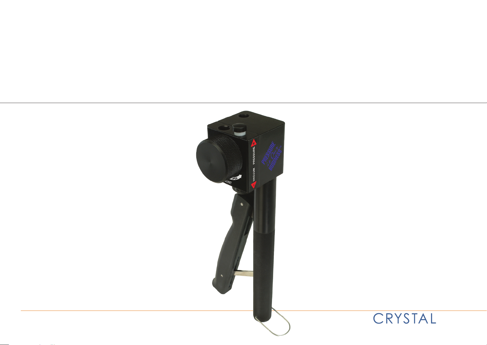
Thank you for purchasing a ComboPump from Crystal Engineering. ComboPumps are precision pressure and vacuum sources. Operate the ComboPump with
just one hand and use the pressure-balanced variable volume to precisely set pressure with just your ngertips. The extra-sensitive check valve allows for
partial strokes to easily reach your target pressure.
There are two pressure ports on top of the pump. Mount a Crystal Gauge or Calibrator directly on top of the pump, connect the spare port directly to the
device being tested, and you have a complete eld pressure calibration system.
All moving parts of the pump mechanism are protected from damage and dirt. There are no exposed springs or piston rods. The body and handle are anod-
ized aircraft grade aluminum and all moving parts are high strength, corrosion-proof plastics and metal. That’s why we are condent your ComboPump will
provide many years of no-maintenance service. If necessary, a rebuild kit is available (P/N 2802), so that you can service the pump yourself.
SPECIFICATIONS
Pressure Range . . . . . . . . . . . . . . . . . . 500 PSI / 35 bar / 3500 kPa
Vacuum Range . . . . . . . . . . . . . . . . . . -12.3 PSI / -0.85 bar / -85 kPa / -25 inHg
Connections . . . . . . . . . . . . . . . . . . . . .Two 1/8" Female National Pipe Thread (NPT)
Overview 1
Weight . . . . . . . . . . . . . . . . . . . . . . . . . . 605 g (1 lb., 5.3 oz.)
Dimensions (H x W x D) . . . . . . . . . . 24 cm x 5 cm x 5 cm (9.5" x 2" x 2")
ComboPump Operation Manual
Page 4

OPERATING INSTRUCTIONS
The ComboPump is only for use with pneumatic systems. Do not use the ComboPump with liquids of any kind.
For safe and reliable operation please read through the following instructions.
WARNING: To prevent damage to the pump and possible injury, never connect the ComboPump to a pressure source greater than 3500 kPa (500 PSIG,
!
Note: The operating pressure rating is printed on the pump body label, on the opposite side of the vent knob.
1 Connections: Your pump has two connections: two 1/8" NPT female pipe thread pressure ports (Figure 1). Always use PTFE (polytetrauoroethylene) tape
on the threads of any pressure ttings installed into the ComboPump.
CAUTION: Do not use liquid pipe sealing compounds (such as "pipe dope"). Be careful not to over-tighten ttings.
!
WARNING: Your ttings must have a pneumatic pressure rating of at least 5000 kPa (750 PSIG, 50 bar).
!
2 Setup: Connect the ComboPump to your test set-up. Move the Shuttle Valve up or down to select whether you want "Pressure Mode"
(up position) or "Vacuum Mode" (down position). Make certain the Shuttle Valve is fully up or fully down (Figure 2).
3 Vent: To close the Vent Knob turn it completely clockwise. Don't overtighten—ngertight is enough (Figure 3).
4 Calibrate: You are now ready to perform your pressure or vacuum calibration. Squeeze the ComboPump handle until the gauge displays a value close to
the desired calibration pressure or vacuum.
35 bar). Turn o, or isolate, all pressure-generating equipment from the pressure tap prior to connecting the ComboPump.
Overview 2
5 Adjustments: To make pressure (or vacuum) adjustments, turn the Variable Volume Adjustment Knob. Set the precise pressure (or vacuum) desired.
It is located on the bottom of the pump next to the squeeze handle (Figure 4).
6 Finish: After the test is complete open the Vent Knob to completely release pressure or vacuum. The Vent Knob can also be used to slowly bleed the system
by opening it only a slight amount and closing it once the pressure or vacuum is reached.
Note: Be sure to close the Vent Knob fully once the system is fully vented, to prevent the knob from vibrating loose when transporting the pump.
Pressure Ports
Figure 1. Connections Figure 2. Setup Figure 3. Vent Figure 4. Adjustments
Shuttle
Valve
Vent Knob
Variable
Volume
Adjustment
Knob
ComboPump Operation Manual
Page 5

CPF Connection Diagram
2908
MPF-1/8MPT
To Transmitter
MPM-1/8MPT
To Transmitter
MPH-XX
MPF-1/8MPT90
Denotes areas where thread-sealing tape is required.
MPF-1/8QTM 1/8" Quick Test NPT Male
MPF-1/8MPT 1/8" NPT Male
MPF-1/4QTM 1/4" Quick Test NPT Male
MPF-1/4MPT
*
1/4" NPT Male
MPF-1/8QTF 1/8" Quick Test NPT Female
MPF-1/4QTF 1/4" Quick Test NPT Female
MPF-1/4FPT 1/4" NPT Female
MPF-1/2QTF 1/2" Quick Test NPT Female
MPF-1/8BSPF G 1/8" Female
MPF-1/4BSPF G 1/4" Female
MPF-3/8BSPF G 3/8" Female
MPF-1/2BSPF G 1/2" Female
MPF-MPF Female to Female
MPF-MPFT U T-Union (Female)
MPF-MPFBULK Bulkhead (Female to Female)
MPF-CAP Cap
MPF-M20QTF M20 x 1.5 Quick Test Female
MPF-M20X1.5F M20 x 1.5 Female
MPF-QCN Quick-Connect Nut
MPF-AN4M AN4 Male
MPF-1/4TBM 1/4" Tube Mal e
MPF-3/8TBM 3/8" Tube Male
MPF-1/2TBM 1/2" Tube Male
MPF-5/16TRM for Foxboro, Rosemount, & Yokogawa
MPF-1/4TRM for Honeywell
NPT MALE
NPT FEMALE
BSP
CPF
ADDITIONAL
TRANSMITTER
Additional N PT sizes available in non- CPF MP adapters
Additional N PT sizes available in non- CPF MP adapters
TUBE
R
RECOMMENDED HOSE AND FITTINGS
CPF Connection Diagram 3
ComboPump Operation Manual
Page 6

Support
CONTACT US
Phone . . . . . . . . . . . . . . . . . . . . . . . . . .(805) 595-5477
Toll-Free . . . . . . . . . . . . . . . . . . . . . . . . (800) 444-1850
Fax . . . . . . . . . . . . . . . . . . . . . . . . . . . . . . (805) 595-5466
Email . . . . . . . . . . . . . . . . . . . . . . . . . . .service@crystalengineering.net
Web . . . . . . . . . . . . . . . . . . . . . . . . . . . . . crystalengineering.net
Send your comments to: sales@crystalengineering.net
CALIBRATION & REPAIR
Please complete the Return Material Authorization (RMA) form. It will generate an authorization number and provide return instructions.
WARRANTY
Crystal Engineering Corporation warrants the ComboPump to be free from defects in material and workmanship under normal use and service for one (1)
year from date of purchase to the original purchaser. It does not apply to batteries or when the product has been misused, altered or damaged by accident or
abnormal conditions of operation.
Support 4
Crystal Engineering will, at our option, repair or replace the defective device free of charge and the device will be returned, transportation prepaid. However, if
we determine the failure was caused by misuse, alteration, accident or abnormal condition of operation, you will be billed for the repair.
CRYSTAL ENGINEERING CORPORATION MAKES NO WARRANTY OTHER THAN THE LIMITED WARRANTY STATED ABOVE. ALL WARRANTIES, INCLUDING IMPLIED
WARRANTIES OF MERCHANTABILITY OR FITNESS FOR ANY PARTICULAR PURPOSE, ARE LIMITED TO A PERIOD OF ONE (1) YEAR FROM THE DATE OF PURCHASE.
CRYSTAL ENGINEERING SHALL NOT BE LIABLE FOR ANY SPECIAL, INCIDENTAL OR CONSEQUENTIAL DAMAGES, WHETHER IN CONTRACT, TORT OR OTHERWISE.
Note: (USA only) Some states do not allow limitations of implied warranties or the exclusion of incidental or consequential damages, so the above limitations
or exclusions may not apply to you. This warranty gives you specic legal rights and you may have other rights which vary from state to state.
ComboPump Operation Manual
Page 7

2909.C
© 2012 Crystal Engineering Corporation
708 Fiero Lane, Suite 9, San Luis Obispo, California 93401-8701
 Loading...