

Page 1
2100 Operation Manual
Introduction
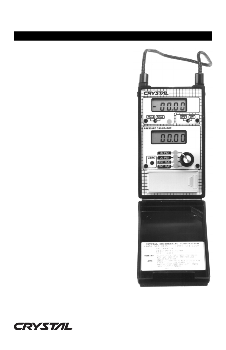
Crystal Engineering 2100 Series Pressure Gauges
and Calibrators measure almost any type of pneumatic or hydraulic pressures and, depending on the
model, up to 500 PSIG. These instruments can also
be used to measure vacuum.
2120s are pressure gauges only, 2121s include a
high accuracy milliamp indicator for simultaneous
display of milliamps and pressure.
A typical application for these instruments is for field
calibration of differential pressure transmitters. The
transmitter being calibrated is isolated from the pipe,
the low side vented to atmosphere and the high
transmitter pressure input is connected to a 2121
and a controllable pressure source (like a handpump). The milliamp signal from the transmitter is
then routed through the 2121 milliamps terminals.
The 2121 indicates the actual transmitter milliamp
output versus true applied pressure. Zero, span and
linearity of the transmitter can be field tested and
calibrated with this system.
All 2100 series instruments use a silicon pressure
sensor with a permanently filled oil isolator. Only the
316 stainless steel diaphragm is exposed to to the
applied media, whether it be gas or fluid. This series
was designed to survive high humidity so the
switches are fully sealed and the circuit boards are
conformally coated.
Gauge pressure models (part numbers ending in -G)
measure the difference between atmospheric
(barometric) pressure, and the pressure (or vacuum)
applied to the pressure port. When the pressure
applied is less than the barometric pressure (i.e.,
vacuum) the gauge will indicate negative pressure.
Absolute models (part numbers ending in -A)
measure the difference between an absolute
reference vacuum and the pressure (or vacuum)
applied to the pressure port. Absolute models will
not indicate negative pressure when vacuum is
applied. The pressure being measured can also be either liquid or gaseous, providing
it is compatible with the materials listed in the specification section.
PN: 2102
8/01
Page 1 of 8
PRESSURE is Our BUSINESS
TM
Page 2

Operating Instructions
To ensure safe and accurate operation, please be familiar with the following operations and
functions.
WARNING:
SEVERE INJURY OR DAMAGE CAN OCCUR THROUGH IMPROPER USE OF PRESSURE
INSTRUMENTS. Do not exceed recommended pressure limits of tubing and fittings. Be certain
all pressure connections are secured. Do not rely on the display indication before disconnecting - it
may not be indicating true pressure.
relieving system pressure.
CAUTION:
NEVER INSERT ANY OBJECT (other than 1/8″ NPT fittings) INTO THE PRESSURE CONNECTIONS!
The sensor diaphragm is very thin and can be damaged or destroyed by solid or sharp objects.
Cleaning of the sensor must be done with appropriate solvents only.
The pressure being measured can be either liquid or gaseous, providing it is compatible with the
materials listed in the specification section. PTFE (polytetrafluoroethylene) tape should be used
with any 1/8″ male NPT fittings installed into the aluminum manifold.
Operating Instructions
The pressure indication must be set to zero without any pressure being applied to the inlet. The
zero adjustment affects all the ranges, but the most precise adjustment is achieved while
monitoring the meter on the 200″H2O range (or the most sensitive range). Turn on the instrument and allow it to warm up for about 1 minute. Using a small screwdriver, adjust the trimming
potentiometer marked
the reading.
Absolute Only:
ZERO
Do not reset zero unless a full vacuum is applied to the meter. If you
are using the gauge for measurements close to barometric pressure,
you may use the zero adjustment to trim in the gauge’s barometric
reading as compared to a precision barometric standard.
Never disconnect pressure instrumentation without first
. Turning the trimming potentiometer counter-clockwise will reduce
The 2100 has two 1/8″ female NPT ports. Two ports are provided so that additional tees should
not be required. We recommend the following when installing fittings:
1. Make sure the ports are free from debris.
2. Select appropriate fittings. Thread sealant must be used. Tighten the fitting into the
pressure port. Use an adjustable wrench on the inlet port manifold to minimize stress on
the case. Do not tighten any more than is necessary to insure a leak-free connection.
Maximum pressure on any instrument is 3 times the highest range. The transducer will not be
damaged when exposed to an overpressure condition within the limits specified, and will not
have to be recalibrated to maintain rated accuracy. Zero may have to be readjusted, however.
PN: 2102
8/01
Page 2 of 8
Page 3
Milliamp Meter
To measure milliamperes, connect any standard test leads (with 4mm banana plugs) to the jacks
on the right side of the meter. The meter meets accuracy specifications with the leads
connected in either polarity. The top jack (red, adjacent to the strap) is the positive input
terminal.
The milliamp meter is internally fused with a replaceable glass, 2 amp, 8 AG fuse. Should the
fuse require replacement, follow the instructions of step 6 in the calibration procedure for panel
removal, then pry out and replace the glass fuse.
Battery Replacement
Replace the battery once a Low Battery indicator becomes visible. The battery warning
indicates the battery is exhausted, and the instrument may no longer be accurate. The 2100
operates on one 9V battery, either carbon-zinc (included) or alkaline. To install the battery, open
the cover of the instrument. Turn the power switch off. Open the battery compartment by lifting
up the tab on the right side of the gauge. Plug the battery into the polarized snap connector.
The power switch must be off when installing the battery, to avoid
!
CAUTION
momentarily connecting the battery in reverse polarity. REVERSE
BATTERY POLARITY WILL DESTROY THE GAUGE IMMEDIATELY.
PRESSURE is Our BUSINESS
PN: 2102
TM
8/01
Page 3 of 8
Page 4

Specifications
Battery: 9V alkaline. Eveready #522 or equivalent.
Low Battery Indication: LCD displays “LOBAT” and/or “LOW BATTERY”
Storage Temperature Rang e: -20 to 70°C (-4 to 158°F)
Operating Temperature Range: 0 to 50°C (32 to 122°F)
Pressure
Temperature Stability: ±0.018% F.S. per °C (maximum) from 0 to 18°C and 28 to
Compensated Temperature Range: 0 to 50°C (32 to 122°F)
Media Compatibility: Liquids and gases compatible with PTFE (polytetrafluoro-
Overpressure rating: 3 times highest pressure range.
Milliamp Meter
Temperature Stability: ±0.01% of reading per °C from 0 to 18°C and 28 to 50°C.
Overload Protection: Internal 2A/8AG/250V user-replaceable fuse.
Battery life: 2120 - 300 hours, 2121 - 100 hours.
Size: Approximately 86mm x 52mm x 168mm (2″ x 3½″ x 6½″)
Weight: 340-425g (12-15 ozs.) with battery, depending on model.
Pressure Ranges: Refer to the chart on page 5.
Accuracy: ±0.1% F.S.* @ 23°C ±5°C. This includes errors due to
linearity, hysteresis and repeatability. The gauge must be
adjusted to read zero at barometric pressure (except for
absolute pressure versions). *or 1 “least significant digit”
on ranges with limited resolution.
Display: 3½ digit Liquid Crystal Display with ½″ digit height.
50°C.
ethylene) penetrated, hard anodized aluminum transducer
housing, 316 stainless steel (sensor), buna-n (0-ring)
Pressure fitting: Dual 1/8″ female NPT (tapered).
Accuracy: ±0.05% of reading (+2 digits on 20 mA scale)@ 23°C
±5°C.
Ranges: 0 to ±19.999 mA and 0 to ±50.00 mA on 50 mA scale.
Display: 4½ digit Liquid Crystal Display with 0.4″ digit height.
Resolution: 0.001 mA on 20 mA scale, 0.01 mA on 50 mA scale.
Burden Voltage: 0.21V @20mA: 0.51V @ 50mA.
Options: Super flexible silicone test lead set - individual Red and
Black banana to banana test leads with hard plastic
insulated banana to alligator clips. Order Part#: AC-1351
Options
1. High Resolution Pressure Display: 4½ digit Liquid Crystal Display. Specify option HR.
Increases resolution on all ranges by one decimal place.
2. Pressure fitting kit. Part#: AC-1391. Includes three 1/8″ NPT to ¼″ tube adapters and
two 24″ pieces of ¼″ polyurethane flexible tubing. For use up to 90 PSI.
3. Quick disconnect set. Part #: AC-1393. One female coupling body with shutoff to male
1
/8″ NPT and one coupling insert to ¼″ plastic tubing adapter.
4. Low pressure pump. Part #: P-102. Includes a variable volume pressure control and
bleed valve. For up to 60 PSIG.
5. Low Pressure Plastic Tubing. Part #: AC-1398. Polyurethane tubing, 0.25″ O.D.,
0.126″ O.D., 90 PSI working pressure.
PN: 2102
8/01
Page 4 of 8
Page 5

Standard Models
Model RANGE 1 RANGE 2 RANGE 3 RANGE 4
212(*)-030PSI-G 199.9²H
212(*)-030PSI-G-HR 199.99²H
212(*)-030HG-G-HR 760.0 mmHg 30.00²Hg 830.0²H
O 830²H2O 19.99 PSI 30.0 PSI
2
O 830.0²H2O 19.999 PSI 30.00 PSI
2
O 30.00 PSI
2
212(*)-200kPa-G 19.99 PSI 50.0 kPa 199.9 kPa 830²H
212(*)-200kPa-G-HR 19.999 PSI 50.00 kPa 199.99 kPa 830.0²H
212(*)-250PSI-G 830²H
212(*)-250PSI-G-HR 830.0²H
O 30.0 PSI 199.9 PSI 250 PSI
2
O 30.00 PSI 199.99 PSI 250.0 PSI
2
212(*)-4²Hg-A 4.00²HgA 1000 mmHgA 15.00 PSIA 30.0²HgA
212(*)-4²Hg-A-HR 4.000²HgA 1000.0 mmHgA 15.000 PSIA 30.00²HgA
(*) insert 1 for millameter, 0 for gauge, only. Other ranges available, contact factory.
Specifications and Model availability subject to change without notice.
0
2
0
2
PRESSURE is Our BUSINESS
PN: 2102
TM
8/01
Page 5 of 8
Page 6

Calibration Procedure
A calibration cycle of 1 year is recommended to maintain the 2100 within specifications. Severe
operating conditions (extreme temperature changes, vibration, etc.) may require a more frequent
calibration cycle.
These procedures assume that you are familiar with proper calibration techniques especially
with regard to high vacuum measurements. (Specifically, a leak free system is required so that
pressure differentials do not occur between the instrument being calibrated and the pressure
standard.) Recommended equipment is listed in Table 1.
Instrument Minimum Specification Recommended Model
Pressure Standard 0.025% of scale Pressurements deadweight
Precision Current Source 0.005% of reading +1µA EDC Model 521
gauge, Model T2300
Absolute Only:
Vacuum Gauge ±1milliTorr @10 milliTorr Hastings VT6S2
Absolute Gauge 0.01% of Scale Ruska PPG-30
Vacuum Pump capable of 1 milliTorr
If you have any questions regarding calibration or repair, please contact us at any of the phone
numbers listed on the back of the manual.
dead-end vacuum
Table 1: Required Equipment
Pressure Indicator Calibration Procedure
Use this procedure to calibrate the 2100 Pressure indicator.
1. Verify the condition of the battery. Make sure that the
battery voltage. Battery voltage must be greater than 7V. Replace the battery if necessary.
2. Connect the instrument to the pressure calibration system. Be sure that the pressure
calibration system and the connection to the instrument being calibrated is leak free.
3. Allow the instrument to stabilize at room temperature, away from drafts, for at least 30
minutes before proceeding with calibration.
4. Set the scale to 200″H2O range (or the most sensitive range [selector switch set fully
counter-clockwise]).
5. The front panel
rotate the front panel
no more increase in output. Then rotate the front panel
turns.
ZERO
potentiometer should be centered. To center the front panel
ZERO
potentiometer fully clockwise until a click is heard, or there is
L0BAT
indicator is not on, or check
ZERO
pot counter-clockwise 15
ZERO
PN: 2102
8/01
Page 6 of 8
Page 7

Absolute gauges only
gauge indicates 10 milliTorr adjust the front panel
equivalent to 0.01 mm HgA, ±0.01 mV.
: Apply full vacuum to the instrument. When the reference vacuum
ZERO
potentiometer for a reading
6. If the zero adjustment range of the front panel
coarse potentiometer must be readjusted. The
located beneath the front zero pot, on the opposite side of the PCB. To take the unit
out of the black case, open the battery case then pull the left side of the black case and
gently pull up on the battery case lid, Be sure not to pull too hard, otherwise you may
pull the sensor out of the unit. Adjust the
close to zero as possible. Trim in the final zero reading with the front panel
potentiometer.
7.1 On the most sensitive range (usually the bottom most range), pressurize to 50% of the
range.
7.2 Adjust the corresponding front panel span pot so that the indication corresponds
exactly with the pressure standard.
7.3 Pressurize to 95% of range. The reading should be within 0.1% of true pressure. If
not, reset the corresponding front panel span pot until the reading is within 0.1% of true
pressure.
7.4 Reduce pressure to 50% of range. The reading must be within 0.1% of range. If not,
repeat steps 7.1 to 7.4 until both readings are within tolerance.
7.5 Reduce pressure to zero. Reading should be within 0.025% of full scale, or ±1 count,
whichever is greater.
7.6 Repeat steps 7.1 through 7.5 for each successive range.
ZERO
potentiometer is inadequate, the
COARSE ZERO
COARSE ZERO
potentiometer is
pot until the output is as
ZERO
2121 Only: Milliamp Meter Calibration
8.1 Connect a precision current source to the milliamp input terminals of the 2121.
8.2 Set mA meter to 20mA scale.
8.3 Apply 19.900 mA to meter.
8.4 Adjust the meter with front panel milliamp potentiometer to read exactly 19.900 mA.
8.5 Apply 4.000 mA to meter.
8.6 Reading must be within ±0.004 mA of 4.000 mA.
8.7 Apply 19.900 mA.
8.8 Set mA meter under test to 50mA scale.
8.9 Reading must be within ±0.04mA of 19.900 mA. (There is no adjustment for this
scale).
PRESSURE is Our BUSINESS
TM
PN: 2102
8/01
Page 7 of 8
Page 8

Warranty
Crystal Engineering Corporation warrants the 2100 to be free from defects in material and
workmanship under normal use and service for one (1) year from date of purchase to the
original purchaser. It does not apply to batteries or when the product has been misused, altered
or damaged by accident or abnormal conditions of operation.
For in (or out) of warranty service, we can be reached at:
Phone ......................... (805) 473-8416 (Direct line to Repair Deptartment)
Toll-Free ....................(800) 444-1850 (Press 6 for Repair Department)
Fax ............................. (805) 595-5466
Email .......................... service@crystalengineering.net
Web ............................www.crystalengineering.net
If calling, have ready the model number, serial number, date of purchase and reason for return.
You will receive instructions for returning the device to Crystal Engineering.
Crystal Engineering will, at our option, repair or replace the defective device free of charge and
the device will be returned, transportation prepaid. However, if we determine the failure was
caused by misuse, alteration, accident or abnormal condition of operation, you will be billed for
the repair.
CRYSTAL ENGINEERING CORPORATION MAKES NO WARRANTY OTHER THAN THE LIMITED
WARRANTY STATED ABOVE. ALL WARRANTIES, INCLUDING IMPLIED WARRANTIES OF
MERCHANTABILITY OR FITNESS FOR ANY PARTICULAR PURPOSE, ARE LIMITED TO A
PERIOD OF ONE (1) YEAR FROM THE DATE OF PURCHASE. CRYSTAL ENGINEERING
SHALL NOT BE LIABLE FOR ANY SPECIAL, INCIDENTAL OR CONSEQUENTIAL DAMAGES,
WHETHER IN CONTRACT, TORT OR OTHERWISE.
Note (USA only): Some states do not allow limitations of implied warranties or the exclusion of
incidental or consequential damages, so the above limitations or exclusions may not apply to
you. This warranty gives you specific legal rights and you may have other rights which vary from
state to state.
Crystal Engineering Corporation
708 Fiero Lane, Suite 9
San Luis Obispo, CA 93401
PN: 2102
8/01
Page 8 of 8
PRESSURE is Our BUSINESS
TM
 Loading...