

Crystal 300PSIXP2I-DL, 100PSIXP2I-DL, 15PSIXP2I, 10KPSIXP2I-DL, 2000PSIXP2I-DL Instruction Manual
...Page 1
XP2i
Operation Manual
for XP2i Digital Test Gauge (Standard and Dual-Display(DD))
Page 2

Contents
Overview ............................................................. 1
Introduction .......................................................... 1
Operating Instructions ................................................. 2
Functions ............................................................ 3
Data Logging with DataLoggerXP .......................... 10
What is DataLoggerXP? ............................................... 10
Installing the Software ................................................ 12
Authorizing a Gauge .................................................. 12
DataLoggerXP Software Operation .................................... 13
XP2i DataLoggerXP Gauge Operation .................................. 18
Excel Templates ...................................................... 22
Enclosure ............................................................ 23
Serial Numbers ....................................................... 24
Specifications ...................................................... 25
Power ................................................................ 28
Pressure Ranges, Display Scales, & Resolution .......................... 29
Part Numbering System ............................................... 29
Support .............................................................. 36
Troubleshooting ...................................................... 36
Calibration . . . . . . . . . . . . . . . . . . . . . . . . . . . . . . . . . . . . . . . . . . . . . . . . . . . . . . . . . . . 37
Software ............................................................. 38
Replacement Parts .................................................... 38
Accessories ........................................................... 38
Contact Us ........................................................... 39
Factory Service ....................................................... 39
Trademarks .......................................................... 39
Warranty ............................................................. 39
Safety & Certifications .......................................... 30
Hazardous Locations .................................................. 30
Certications ......................................................... 30
ATEX/IECEx Safety Instructions ........................................ 31
Page 3
Overview
INTRODUCTION
Thank you for choosing the XP2i Digital Test Gauge from Crystal Engineering Corporation. Your XP2i is a combination of leading edge technology and rugged
industrial design.
–
Accuracy is 0.1% “of reading”, 0.02% “of Full Scale” or 0.05% “of Full Scale”
–
The XP2i is fully temperature compensated
The XP2i’s case is made from rugged aluminum alloy utilizing a gasket to seal the enclosure against dust and water intrusion. Even the RS-232 connector is
fully sealed (with or without the red cover or rubber boot). Circuitry is mounted in shock absorbing elastomer supports and the batteries are easily accessible
by removing four screws. But you won’t need to change the batteries often, since 3 AA batteries operate the XP2i for up to 1500 hours of continuous use.
Other features include:
Continuous capture of peak and valley pressure readings
•
PSV mode
•
Programming interface
•
User-dened units
•
Intrinsically Safe
•
All welded 316 stainless steel sensor
•
Calibration due reminder
•
We hope your XP2i meets your expectations, and we're interested in any comments or suggestions you may have. You can send us a note at:
crystal@ametek.com. Many features in this and our other products are a direct result of your comments!
rystal Engineering is the company that designs, manufactures, markets, and services the nVision reference pressure recorder, XP2i, and 30 Series pressure
C
calibrators, M1 Pressure Gauge, MultiCal multimeter pressure adapters, and a variety of industry specic pressure measuring equipment. Crystal Engineering
pioneered features like full temperature compensation and “of reading” rated gauges and calibrators. Pressure measuring equipment is the only thing we do
and that’s why we say:
so there is no change in accuracy throughout the entire operating temperature range!
so any XP2i can typically replace several gauges you may have been using.
Overview 1
Your XP2i can be customized, through the use
of our free CongXP™ software. Your personal
computer can disable, enable, or modify a
variety of features of your XP2i. Look for the
logo for
programmable features, like:
A user dened pressure scale, and/or disable
•
unused pressure units
Password protection to prevent
•
unauthorized changes
Disable keypad recalibration, (peak)
•
button, and/or
(units) button
™
Expand or decrease allowable Zero range
•
Set the gauge to a dierent density of water
•
factor (4° C, 60° F, or 68° F)
Store a 12 digit ID or tag number in
•
non-volatile memory
Adjust calibration values
•
XP2i Operation Manual
Page 4

OPERATING INSTRUCTIONS
The XP2i is shipped with batteries installed, so it’s ready to use. Press and hold the (on/o) button. The XP2i will rst test all LCD segments. Release
(on/o) button when the XP2i indicates pressure.
the
The XP2i always resumes operation in the mode and the units of the pressure last used, and it does not automatically rezero when turned on.
Connect the XP2i to your system.
CAUTION: Use a wrench (¾" or 19mm) for installation and removal of XP2i! There is a limit to how much rotational force can be applied to the case, so
!
CAUTION: Never insert any object into the pressure connection! The sensor diaphragm is very thin and can be damaged or destroyed by solid or sharp
!
WARNING: Severe injury or damage can occur through improper use of pressure instruments! Do not exceed recommended pressure limits of tubing
!
Most XP2i’s are intended for gauge pressure measurement. That is, they indicate the dierence between applied pressure and ambient barometric pressure.
However, the
default setting limits the maximum zero value to 20 psi, but this limit can be changed with
Some XP2i’s are rated for absolute pressure. Absolute gauges indicate the dierence between applied pressure and an internal vacuum reference. Absolute
pressure is always positive. For instance barometric pressure at sea level is on average about 14.7 psi (approximately 100 kPa or 1 bar), so at sea level this is the
lowest expected pressure indication. However, absolute gauges can be “zeroed” (unless prevented by CongXP). After zeroing an absolute gauge it is possible
to indicate a negative or positive gauge pressure.
don’t rely on, or use, the case to screw the XP2i into a tting, and don’t use the case to remove the XP2i tting, either.
objects. Cleaning of the sensor must be done with appropriate solvents only.
and ttings. Be certain all pressure connections are secured.
(zero) button can be used to force an XP2i to read zero pressure at any applied pressure, up to the full scale rating of the gauge. The factory
.
Overview 2
WARNING: This gauge can display zero pressure when connected to a source of pressure! Do not rely on the display indication before disconnecting—
!
it may not be indicating true pressure. Never disconnect pressure instrumentation without rst relieving system pressure!
XP2i Operation Manual
Page 5
Functions
units
Units Button
Pressing this button causes the XP2i to select the next available unit of pressure measurement.
See Pressure Ranges, Display Scales, & Resolution on page 29 or the list of pressure units available for your model.
Units that you don’t need or never use can be turned o. You can also dene a special unit for your XP2i with CongXP. You can
use the XP2i to display directly in a unit not otherwise available, such as feet of seawater, or foot-pounds of torque. When you select your custom unit from the
keypad, the screen displays the USER icon.
Hi
Peak Button
peak
Lo
Functions 3
On the XP2i, pressing the (peak) button causes the display to cycle
through the following , depending on your setting in CongXP.
<No Icon> . . . . Live Pressure display
. . . . Maximum detected pressure
. . . . Minimum detected pressure
(blinking)
(blinking)
. . . . PSV Mode, maximum
. . . . PSV Mode, minimum
Average pressure
. . . .
. . . . DataLoggerXP datalogging mode
*
*
* From the factory this setting is disabled. Use CongXP to enable.
Peak High and Peak Low values are not saved when the gauge shuts o; they will reset to the current
reading when the XP2i is turned on or reset.
In some cases the ability to display a peak value may not be needed, or
may even be dangerous. CongXP allows you to disable this button.
XP2is can average 1 to 10 readings, recalculated every time pressure is measured (4 times per second).
Enable and set the number of readings to be averaged with CongXP.
On the -DD, dual-line display XP2i, pressing the
through the following, depending on your setting in CongXP:
<No Icon> . . . . Live Pressure display
. . . . Maximum detected pressure
. . . . Minimum detected pressure
(blinking)
(blinking)
. . . . PSV Mode maximum
. . . . PSV Mode minimum
. . . . Average pressure
. . . . DataLoggerXP datalogging mode
(remaining points displayed on lower line)
*
. . . . Tare
. . . . Rate of change
. . . . Dierential Mode
. . . . Average Dierential Mode
+
(peak)
button causes the display to cycle
*
*
*
*
*
XP2i Operation Manual
Page 6
zero
Resetting (Clearing) Recorded Peak Values
HI
LO
zero
clear
Peak values can only be cleared when displaying either a Peak High or Peak Low recorded pressure. Press the (clear) button for at least ½ second. Dashed
lines will briey appear across the display indicating that both Peak values have been cleared. Both Peak High and Peak Low values will then display the cur-
rent applied pressure. Pressing the
need to rezero the gauge, you must turn o both peak icons by pressing the
(clear) button while either the Peak High (
) or Peak Low (
(peak) button.
) icon is displayed will not aect the zero value. If you
Zero
clear
If you attempt to zero the gauge while applying a pressure which exceeds the Zero Limit (set in CongXP, defaults to 20 psi),
the command will be ignored and “--HI-” will be displayed.
X
To Zero the XP2i
Turn o peak indication by pressing the (peak) button repeatedly until the HI and LO icons are o, then press the (zero) button for at least ½ second when
the gauge is vented to atmosphere.
Functions 4
The display will then briey ash all dashed lines (
WARNING: This gauge can display zero pressure when connected to a source of pressure! Do not rely on the display indication before disconnecting—
!
X
To Clear the Zero Value on an XP2i
Turn o peak indication as described above, then press and hold the (zero) button until the display changes from (
This is especially useful for absolute gauges that have been zeroed to use for gauge pressure measurement.
it may not be indicating true pressure. Never disconnect pressure instrumentation without rst relieving system pressure!
), indicating that it has been re-zeroed. Absolute gauges will now indicate gauge pressure.
) to (
).
XP2i Operation Manual
Page 7
Functions 5
HI
LO
(
Tare
-DD, Dual-Line Display XP2i Only
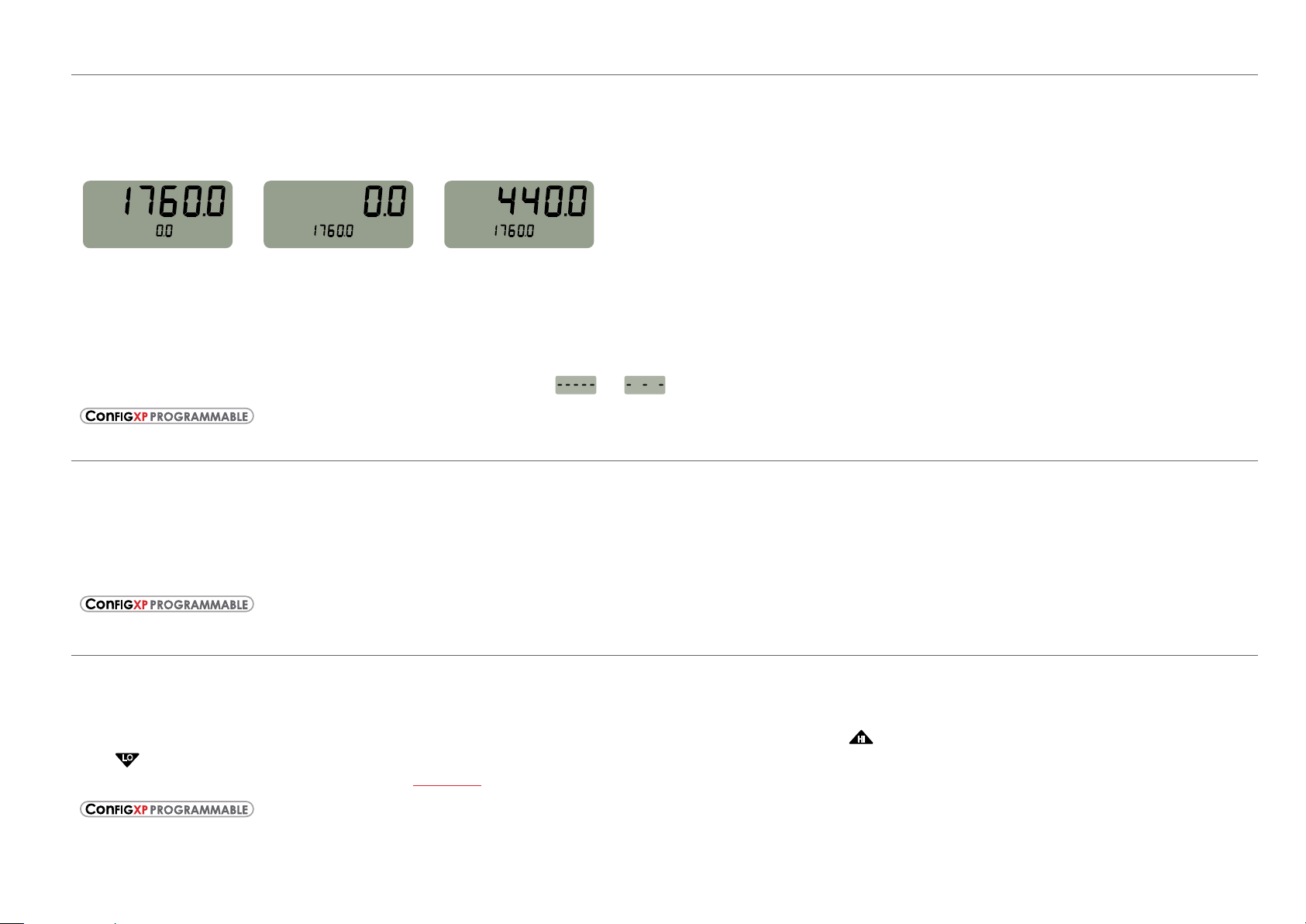
Tare is a constant value subtracted from the true pressure. For instance, if you were mixing gases by partial pressure, you might want to ll a tank to 1760 psi
with air, then add another 440 psi of helium. To reduce the chance of error, you could tare the gauge at 1760 psi. Then you would add helium until the indica-
tion reached 440.
PSI
TARE
Fill to pressure Press the Tare button Top-o with helium
In contrast to the Zero function discussed previously, Tare is not subject to the Zero Limit set in CongXP. Tare is available only when the TARE icon is on. To
use the Tare feature, press the
not be indicated on the screen. Apply pressure to the gauge until you reach the desired value. Press the
pressure to zero. The amount of the tare will be displayed on the second line.
To clear the tare, press and hold the
(
Rate
-DD, Dual-Line Display XP2i Only
Rate is the measurement of pressure change per minute. When in Rate mode, the second line will display the rate, and the /min icon will display. Rate is
calculated at every pressure measurement (4 times per second), and the displayed value is the average of the most recent 3 to 10 calculations. By increasing
the number of calcula
(peak) button repeatedly until the screen displays the TARE icon. The TARE icon will ash to remind you that live pressure may
(zero) button until the tare value changes from (
The Tare function is disabled by default, but can be enabled with CongXP.
tions in the average, the XP2i will indicate a more stable rate. However, the XP2i will react more slowly to changes in rate.
)
TARE
)
PSI
TARE
PSI
(zero) button. The top line will change from true
) to (
).
To use the rate feature, press the
be set with the digital interface.
Dierential Mode
Dierential mode allows the XP2i-DD gauge (the master) to be connected to a second XP2i or XP2i-DD gauge (the slave) and display the pressure dierence
between the two gauges. A standard RS232 cable (p/n 2400) and null modem adapter (p/n 3456) or a null modem cable are required to directly connect the
gauges. You must use CongXP to enable this feature, and once enabled, use the
Low (
rmware version R0014 or later for this feature to work. Use XP2iUpdate to upgrade to the latest rmware.
) icons are displayed simultaneously. An XP2i-DD gauge must be running rmware version R0114 or later, and an XP2i gauge must be running
(
(peak) button repeatedly until the /min icon displays. As pressure changes, the second line will indicate rate of change.
The rate function is disabled by default, but can be enabled and congured with CongXP. The number of calculations can also
-DD, Dual-Line Display XP2i Only
The dierential mode is disabled by default, but can be enabled and congured with CongXP.
)
(peak) button on the master gauge until the Peak High (
) and Peak
XP2i Operation Manual
Page 8

Automatic Shut-o
The XP2i has a shuto timer and will turn o automatically after 20 minutes of non-operation. Pressing any button or sending any command via the RS-232
connection resets the shuto timer for another 20 minutes of operation. The XP2i will briey display Auto O 20 when turned on.
Functions 6
To disable the shuto feature, turn on the XP2i by pressing the
O to indicate that it will not turn o. The shuto feature can be enabled again when turning the XP2i on, by pressing the same
These settings are retained when the product is powered down.
Note: This key combination will not toggle the auto-shuto feature if CongXP is set to require a password before changing settings.
(on/o) and (zero) buttons simultaneously. The XP2i will briey display the words No Auto
(on/o) and (zero) buttons.
Backlight
Pressing the (backlight) button instantly lights the display at maximum brightness. Hold down the button for 1 second to keep it on. The display will ash
briey, indicating that it will stay on for 1 minute. If you press the
tery life, and remain on for 2 minutes after the last key is pressed. Press the
If you start the XP2i in the No Auto O mode, you may select the brightness level in the same way. The light will never time out and turn o. Turn o the XP2i,
or press the
(backlight) button repeatedly, to turn o the backlight.
(backlight) button again, the backlight will go into a lower brightness setting to extend bat-
(backlight) button once more and the light will go out.
Measuring Vacuum
All versions of the XP2i can be used to measure moderate vacuum, though only ranges of 300 psi (and 20 bar or 2000 kPa) and lower are actually tested and
certied for vacuum operation.
When measuring pressure less than ambient barometric conditions, a minus (-) sign will appear.
Absolute gauges (models with a “B” in front of “XP2i” in the part number) will NOT indicate a negative sign when vacuum is applied, unless the
has been pressed while a pressure greater than full vacuum is applied to the gauge. If your absolute gauge does indicate a negative pressure, you can clear
the zero value (“unzero”) by pressing the
(zero) button until the display changes from (
) to (
).
(zero) button
CAUTION: XP2is are not recommended for continuous use below -14.5 psig.
!
For continuous use below -14.5 psig with high accuracy, choose our XP2i-DP Dierential Pressure Gauge.
XP2i Operation Manual
Page 9
Water Density (Inches of Water)
HI
LO
HI
LO
The following applies only to models where inches of water is a selectable pressure unit. As shipped from the factory, the XP2i is set to display inches of water
corresponding to the density of water at 4° C (39.2° F). You may require a dierent water density for your application, so the XP2i can be set to use the density
of water at 20° C (68° F) or 15.6° C (60° F) instead.
Functions 7
To check and/or change the water density setting from the keypad, turn on the XP2i by pressing the
The display will indicate either 4C, 60F, or 68F.
Press the
Note: If the XP2i is password protected, or inches of water is disabled, you will not be able to view or change the water density from the keypad.
(units) button until the display cycles to the desired water density, then press the (zero) button to store the selection (this will not zero the gauge).
Select and set the desired density of water.
(on/o) button and the (peak) button simultaneously.
Overpressure Conditions
The XP2i will read pressure up to approximately 110% of the rated pressure range. Above 110%, the display will indicate +OL, and readings will stop updating.
The zero function does not aect when the display will indicate +OL, so depending on the zero value it is possible that the display will indicate +OL without
the maximum pressure being displayed.
For instance, if a 100PSIXP2i is zeroed when 30 psi is being applied, it will indicate that the overpressure condition has been reached at 80 psi
(i.e., 110% x 100 psi – 30 psi = 80 psi).
verpressure can aect accuracy, but the eect is only temporary unless the sensor has been destroyed. See Pressure Ranges, Display Scales, & Resolution
O
on page 29 for maximum overpressure.
PSVtest Mode
PSVtest mode is designed for PSV and PRV (“Pressure Safety Valve” and “Pressure Relief Valve”, respectively) as well as for Rupture Disc (also known as “Burst
Disc”) testing. It increases the measurement rate of the XP2i gauge to approximately eight times per second, to capture the peak pressure when the valve
opened, and adds a method of automatically capturing the closing reseat pressure.
Use CongXP to activate PSVtest Mode. When the Peak High icon (
tomatically reset to the Peak High value whenever a new Peak High value is detected. Once pressure stops increasing, as when a PSV opens (and the pressure
ops below the maximum pressure) XP2i detects the new minimum pressure values (the Peak Low), capturing the closing pressure of a PSV.
dr
Press the
To clear the peaks, press the
Application note AN-006
to use the gauge in relief valve and burst disk testing.
(peak) button once to view the captured reseat pressure. The Peak Low icon (
(clear) button while the display shows the High (
–
Pressure Safety Valve Testing detailing the operation of the PSVtest mode is available on our website, and includes examples on how
) ashes, PSVtest mode is enabled. A special feature of PSVtest is that Peak Low is au-
) will ash on the display.
) or Low (
) icons.
XP2i Operation Manual
Page 10
Calibration Due Reminder
The XP2i has a calibration reminder feature that can help to assure that you never use the gauge after its calibration certicate has expired. It can be pro-
grammed to alert you prior to, on, and after the gauge’s calibration due date. Due dates, reminder times, and message types can be set through our free
ongXP software.
C
X
Calibration Reminder Alert
Enter the Cal Due date and the notication time prior. Once the dened time prior is reached, the XP2i will ash Cal Soon three times during the startup pro-
cess. It will do this on every start-up until the calibration due date is reached, or the dates are updated.
X
Calibration Due Alert
Once the calibration due date has been reached, the XP2i has three options to choose from. On Startup, will ash Cal Due three times during the startup pro-
cess. After this, no additional warnings will occur until power is recycled again. Alternate, will alternate displaying Cal Due and live pressure readings. Always,
will displa
Password Protection to make the gauge non-operational and always display Cal Due.
Note: Protect the settings by using password protection.
y Cal Due until a button is pressed and then the gauge operates normally. After this, no additional warnings will occur until power is recycled. Add
Low Battery Indication
The Battery icon ( ) uses three bars to display the battery level. When the icon displays all three bars, the batteries are full. The XP2i will continue to operate
accurately while the icon is visible. When the batteries are exhausted, the letters batt will appear across the display. After batt appears, no pressure measure-
ments will be possible until the batteries are replaced.
Functions 8
Battery Replacement
The XP2i uses 3 AA batteries. Loosen the four rear panel screws to gain access to the battery compartment. These four panel screws are captive inside the
panel and are not removable. Pull the panel up to expose the battery compartment. After replacing the batteries, the XP2i will start operating immediately
(without having to press the
WARNING: Do not remove or change the batteries in hazardous locations.
!
WARNING: T4 or T3 Temperature Class is based on selection of approved battery. See the table below.
!
CAUTION: Do not mix battery types or manufacturers.
!
ATEX/IECEx: The XP2i is Intrinsically Safe only if powered by one of the following battery types:
Approved Battery Type Ta= Marking
Rayovac Max Plus 815
Energizer E91
Energizer EN91*
Duracell MN1500
Energizer is manufactured by Energizer Holdings, Inc., and the Eveready Battery Company, Inc.
*
*
(on/o) button). This indicates that a complete reset has occurred, and is normal.
-20 to 50 ° C Ex ia IIC T4 Ga
-20 to 50° C Ex ia IIC T3 Ga
XP2i Operation Manual
Page 11
Many other battery types and models have been tested but failed to meet the requirements for Intrinsic Safety—do not assume other models are equivalent.
The XP2i can be operated from an external power supply (AC adapter kit PN: 2984).
WARNING: Do not use AC adapter in hazardous locations.
!
CSA: The XP2i is Intrinsically Safe only if powered by one of the following battery types:
CSA: The XP2i est un système à sécurité Intrinsèque seulement s’il est alimenté par un des Piles de type suivant:
Functions 9
Approved Battery Type
(Approuvé Type de Batterie)
Rayovac Max Plus 815 -20 to 45° C
Energizer E91
Energizer EN91
Rayovac Max Plus 815
WARNING: Use of Duracell MN1500 batteries is not approved for CSA certication.
!
Ta=
-20 to 50° C
Class I, Division 1, A, B, C, D T4
(Classse I, Division 1, A, B, C, D T4)
Class I, Division 1, A, B, C, D T3C
(Classse I, Division 1, A, B, C, D T3C)
Marking
(Marquage)
Reset
If for some reason the XP2i needs to be reset, remove any battery for at least one minute, then reinstall the battery. If the reset is successful, the XP2i will
start operating without pressing the
default engineering units.
WARNING: Do not remove or change the batteries in hazardous locations.
!
(on/o) button. Reset will clear the zero, peak values will be reset to the current reading, and the XP2i will be set to the
Communications/Programming
The XP2i responds to a query-based command language which allows remote control of the gauge. Please refer to the XP2i Programming Instructions for
documentation of this feature.
XP2i Operation Manual
Page 12

Data Logging with DataLoggerXP
WHAT IS DATALOGGERXP?
DataLoggerXP is an optional data logging mode available for the XP2i gauge. You may purchase the DataLoggerXP option with your original order
or add it later.
ith the XP2i’s long battery life, and Ultra Low Power (ULP) mode, you can log data over an entire year, without the need for external power supplies or
W
battery replacements.
ownload the DataLoggerXP software from the Crystal website and use it to save the data recorded on your XP2i.
D
Note: An evaluation mode allows you to record 100 data points before requiring purchase.
With an XP2i and DataLoggerXP you can:
Record up to 32 000 pressure measurements (data points) into non-volatile ash memory.
•
Save battery life and record over an entire year with Ultra Low Power (ULP) mode.
•
Change data collection parameters, with or without a computer.
•
Start and stop multiple collection runs from the keypad.
•
Record pressure readings at intervals as fast as once per second or as slow as once every 18 hours.
•
Record the averages, averages and peaks, or just the pressure indication.
•
Store an indicated pressure by pushing one button.
•
View the data on any Windows-equipped computer.
•
Data Logging with DataLoggerXP 10
Save the data les directly into Microsoft® Excel spreadsheets (requires Excel 2003, 2007, or 2010), or as comma separated text les.
•
XP2i Operation Manual
Page 13

DataLoggerXP Terminology
Clear. . . . . . . . . . . . . . . . . . . . . Removes all stored data from the XP2i memory. Individual runs cannot be removed.
Download . . . . . . . . . . . . . . . The act of copying stored data from the XP2i to a computer using DataLoggerXP software.
Events . . . . . . . . . . . . . . . . . . . Non-data readings, optionally displayed as part of a run. These include tare values, low battery indications, or logging parameters.
Logging Interval . . . . . . . . . The time, in seconds, between each data point.
Logging Type . . . . . . . . . . . . The type of data stored for each reading.
Logging Parameters . . . . . The Logging Interval and Logging Type are referred to, in this document, as the Logging Parameters.
Run . . . . . . . . . . . . . . . . . . . . . . A set of one or more readings taken by the XP2i. The user can specify dierent logging parameters for each successive run.
Note: A maximum of 64 runs can be stored in memory.
Typical Usage
While there are a variety of ways in which the DataLoggerXP software and XP2i can be used, a typical way to use the DataloggerXP
might be like this:
Data Logging with DataLoggerXP 11
Set the logging parameters
1
2 Enable data logging mode (the Record icon (
3 Take a recording.
4 Use DataloggerXP software to download your data into an Excel worksheet or a text le.
–
either with DataLoggerXP software or directly from the keypad.
) will illuminate).
XP2i Operation Manual
Page 14

INSTALLING THE SOFTWARE
DataLoggerXP can either be installed from a CD provided by Crystal Engineering, or downloaded from the Crystal Engineering website.
We recommend you check the website for the latest version.
Installing from the CD
Run the Setup.exe application located on the install CD. This is typically D:\Setup.exe, but may be dierent on your computer.
Installing from the Internet
Visit ametekcalibration.com and select the DataLoggerXP software page to download the latest version of the software.
Once the setup application begins, follow the on-screen prompts to complete the installation. If DataloggerXP is being upgraded, the prior version does not
need to be uninstalled, as the new version will be installed over any existing version.
AUTHORIZING A GAUGE
The gauge must be authorized using a purchased authorization key to obtain the full 32 000 data point recording capability. The key is specic to a gauge’s
serial number, and can only be used with the gauge it was meant to authorize.
To Authorize a Gauge
Data Logging with DataLoggerXP 12
1 Connect the gauge to your computer.
2 From the File menu, choose Authorize Gauge to start the Authorization Wizard.
3 Follow the on-screen instructions.
XP2i Operation Manual
Page 15

DATALOGGERXP SOFTWARE OPERATION
As described in the prior section, the DataLoggerXP application provides complete control of the settings for data logging mode on the XP2i. You can change
logging parameters and download data using the application. In this section, you will nd a description of each of the functional areas of the application.
The DataLoggerXP Main Window
Data Logging with DataLoggerXP 13
Working in the Main Window
X
Setting the Options
By default, DataLoggerXP is congured for automatic serial port detection. However, in some cases automatic serial port detection may not work.
To select a specic serial port, open the Options dialog box, by choosing View
If your installation supports additional langauges, you can choose the language from the Select Language drop-down list. The settings for Excel templates
are covered in Excel Templates on page 22.
> Options. Select the serial port and press OK to save any changes.
XP2i Operation Manual
Page 16

X
To Connect to the Gauge
1 Plug the serial cable into the computer and XP2i gauge ports.
2 In the DataLoggerXP main window, click Connect.
Data Logging with DataLoggerXP 14
The program will retrieve the current logging parameters, and then allow downloading, viewing, and saving data, as well as updating the logging
parameters.
X
Password Protection
The password protection feature of the gauge allows you to prevent unauthorized changes to the data logging parameters. Once the password is set, the
Send to Gauge button will require the password. Changing logging parameters and Auto-O settings through the keypad will be disabled. Passwords can
only be set or removed using DataLoggerXP or CongXP. In the event you lose the password, you will need to contact the factory for an unlock code, which
will remove the password protection. To set a password:
1 In the DataLoggerXP main window, click the Set Password button.
2 In the Change Password dialog box, enter and conrm your password and click OK.
XP2i Operation Manual
Page 17

Data Logging Parameters
Logging parameters can be set up one of two ways: on a computer connected to an XP2i, or from the XP2i keypad. This second option allows the user to make
changes in the logging parameters while in the eld. Once the logging parameters have been selected, the gauge can begin recording data. The two param-
eters that aect data logging (logging interval and logging type) are covered below.
X
Logging Interval
The logging interval controls how frequently the gauge takes a measurement. XP2i data logging features a minimum recording time of 1 second and a
maximum recording time of 18 hours.
X
To Choose a Logging Type
From the Logging Type drop-down list, choose a logging type.
Data Logging with DataLoggerXP 15
The gauge may operate in ve logging types:
Actual: The gauge stores the value displayed on the gauge at each logging interval.
•
Average: The gauge calculates and stores the average of all readings taken (4 per second) during each logging interval. For example, if the recording interval
•
is 10 seconds, the logged value is the average of the last 40 readings (10 seconds x 4 readings/second).
Average with Peaks: The highest and lowest value of each logging interval is recorded along with the average value.
•
On Demand: This mode diers from the other three, in that the logging interval does not apply. Press the (peak) button to store the displayed pressure
•
value and the current timestamp.
Actual-ULP: Similar to Actual; Ultra-Low Power mode extends recording time to over an entire year on one set of batteries. The gauge will display ULP
•
instead of the live pressure. Stop the recording to view the live pressure display.
XP2i Operation Manual
Page 18

Data Management
X
To Download Data from the Gauge
1 Connect the gauge to your computer.
2 In the DataLoggerXP main window, click the Download button.
Depending on the number of readings, it can take up to 15 seconds to download all the data. Once the data has been downloaded, the View and
Save buttons will be available.
X
To View a Data Run
In the DataLoggerXP main window, click the View button to open the Data View dialog box.
Data Logging with DataLoggerXP 16
In the Data View dialog box, you can select the run you wish to display, and choose to include or exclude recording events. Events are non-data readings, such
as tare values, low battery indications, or logging parameters.
XP2i Operation Manual
Page 19

X
To Save a Data Run
In either the DataLoggerXP main window or the View Data dialog box, click the Save button.
Save button in the DataLoggerXP main window.
Save button in the View Data dialog box.
You may download one recording run at a time. Each run will be saved to a separate le. The application will rst ask for which data run to save, and then the
name of the le to save. A le can be saved as either an Excel workbook or comma separated text le (”.txt” or “.csv”) format.
X
To Save a File in Excel Format
From the Save as type dropdown box in the Save As dialog box, choose either an Excel template le (ending in “.xlt”), or an Excel workbook le
(ending in “.xls”).
Data Logging with DataLoggerXP 17
f you choose the Excel template (“.xlt”) a new Excel document will be created using that template. If you choose the Excel worksheet (“.xls”), you must have
I
already selected the default Excel template in the Options dialog box. The Excel le will be created and saved using this default template.
For more information, see Excel Templates on page 22.
f the le name does not include a “.xlt” or “.xls” extension, the data will be saved as a comma separate text le (ending either “.txt” or “.csv”) of that name.
I
X
To Clear All Data Runs
In the DataLoggerXP main window, click the Clear button to erase all runs from the gauge, making all memory available for the next sequence of runs.
XP2i Operation Manual
Page 20

XP2I DATALOGGERXP GAUGE OPERATION
When in data logging mode, XP2i provides data logging capability along with many of the features of a standard XP2i. In order to allow operation as a data
logger, some of the standard functionality of the standard XP2i is suspended.
Maximum Number of Readings
An XP2i with the authorized DataLoggerXP option can record up to 32 000 data points. By holding down the (units) button you can see the number of avail-
able data points on the gauge after the status is displayed. To avoid starting a recording, release the
points. The Dual Display (-DD) XP2i will display the number of available points on the second line, anytime data logging mode is selected.
(units) button after you see the number of available
Recording Pressure
1 Press the (peak) button repeatedly until the record icon ( ) illuminates in the top left corner.
2 Connect the gauge to the pressure line to be monitored.
Data Logging with DataLoggerXP 18
3 Press and hold the
The units icon will blink to indicate a logging run is in progress.
The gauge displays the current state, then the number of data points available, and then the new state.
4 Once the test is complete, press and hold the (units) button again until it says Stop.
(units) button on the gauge until it says Start—data is now being logged.
XP2i Operation Manual
Page 21

Keypad Usage
The following buttons and button combinations are used to control data logging runs on the XP2i. Where two keys are indicated, the operation is executed by
pressing and holding down the rst key, then pressing and holding down the second key until the action is completed.
Note: Start by turning o the gauge. Then use the following keypad shortcuts, in the order they appear.
units
X
Units + Power: Setting Logging Parameters (Mode and Interval)
Used only when the gauge is turned o, this allows you to select the logging type and interval from the keypad.
+
Data Logging with DataLoggerXP 19
Press the
(peak) button repeatedly to cycle through the logging types. Press the (units) button to accept the format.
Actual
Average
Average with Peaks
On Demand
Actual Ultra Low Power
For further information, see Ultra Low Power (ULP) Mode on page 21.
X
Setting the Logging Interval
The display will advance to the logging interval, displayed in seconds. The (peak) button lengthens the logging interval. The (zero) button shortens the
logging interval. The
Note: At this point, the record icon (
(units) button accepts the logging interval and the display reverts to normal.
) will illuminate on the display.
Note: If you select the On Demand logging type, you will not be asked to select a logging interval.
XP2i Operation Manual
Page 22

Data Logging with DataLoggerXP 20
zero
Lo
HI
LO
Units
units
X
Pressing and holding the (units) button briey causes the XP2i to display information about the logging state. If you continue to hold the (units) button, a
logging run will begin or end. Immediately after pressing the
(units) button, the gauge will display the operating mode as one of these values:
The logging memory is Clear, data is empty, and the XP2i is idle.
The XP2i is currently logging data.
The XP2i is logging in On Demand logging type.
The XP2i is not currently logging data and it contains stored data.
The XP2i is not logging data and memory is Full.
Authorization is required before additional logging is allowed.
If you continue to hold the
Holding the
If the gauge is in a Clear or O state, the gauge will briey display Start, begin logging data, and change its state to On.
•
If the gauge is in an On state, it will stop logging, briey display Stop, and change its state to O.
•
The Full state will not change by holding the (units) button. In order to get out of the Full state, you must clear the logging memory as shown below.
•
(units) button even longer will then cause the operating state to change as follows:
(units) button, the number of remaining data points available in memory is displayed.
units
X
Units + Zero
+
clear
Holding these two keys will clear the logging memory of the XP2i. If the gauge is recording, you must rst stop logging as described above. When these but-
tons are pressed, the gauge will rst display its current state (O,
CLr, etc), then the number of data points available, and then CLr, indicating the clear action
was successful.
Hi
peak
X
Peak
When the logging type is set to On Demand (Pb), hold down the (units) button to begin recording. The units icon will ash. Press the (peak) button to
record the displayed reading. Each time a data point is stored, the Peak High (
) and Peak Low (
) icons will blink. Hold down the (units) button again
to stop recording mode.
XP2i Operation Manual
Page 23

Ultra Low Power (ULP) Mode
HI
LO
The XP2i can log for extended periods with Ultra Low Power Mode, activated by the key combinations explained in Keypad Usage on page 19.
Ultra Low Power Mode takes readings in Actual Mode, according to the set logging interval. The letters ULP replace the live pressure reading during
a recording. You must stop the recording to view the live pressure.
o begin or end a recording hold down the
T
Note: To maximize battery life and recording time in ULP Mode, limit your use of the backlight.
(units) button.
Operating Behavior
Data Logging with DataLoggerXP 21
Each time a data point is stored, the Peak High (
ging is active, the unit icon will blink.
) and Peak Low (
) icons will blink, giving you visual feedback as data points are recorded. While log-
XP2i Reset or Battery Change
Data collected by the XP2i will not be lost with a gauge reset or battery change, although any run in progress will be stopped. A reset or battery change will
aect the operation of the gauge’s real-time clock. When the XP2i is connected to DataLoggerXP and the logging parameters are set, DataLoggerXP also sets
the gauge’s real-time clock. However, if the gauge resets, or if the batteries are changed or become momentarily disconnected (if the gauge is dropped to the
oor, for instance), the real-time clock may be reset. When this occurs, the time stamps of subsequently logged data will no longer be correct. DataLoggerXP
reacts to this by attempting to resynchronize the gauge’s clock with the computer’s clock which will allow the time stamps to be correctly read. However, if
multiple resets have occurred with the gauge, only time stamps after the last reset will be xed. When a reset occurs, it is stored as a run with a reset event and
no data.
XP2i Operation Manual
Page 24

EXCEL TEMPLATES
In order to provide for a exible reporting solution, DataLoggerXP is capable of directly interfacing with Microsoft® Excel to paste run data for reporting and
graphing. DataLoggerXP supports Excel 2003, 2007, and 2010. This section assumes some familiarity with Excel.
Note: For information on how to save data to the dierent le types see To Save a File in Excel Format on page 17.
DataLoggerXP uses an existing Excel template le to create a new workbook. This allows any amount of formatting or graphing to be edited beforehand and
stored as a template le. Then, when the Excel workbook is created, the template le is opened and data is copied to the location specied in the Options
dialog box. When selecting the template le directly during the le save process, the new workbook is created with the Excel template using the name of the
template le followed by a number, typically "1." The user must also save the le manually, making any changes to the le name as necessary.
The default template le, dataloggerxp.xlt, is located in the DataLoggerXP program directory, and can be used as–is or modied to meet the user’s require-
ments. The default template produces a graph with an elapsed seconds time base. Choose one of the other appropriately named templates to graph with a
time base of minut
es, hours, or timestamps in DD-MM-YY or MM-DD-YY formatting.
Excel Password Protection
It is possible to password protect the Excel workbook by selecting the Password Protect Excel Documents checkbox in the Options dialog box. Only the data
sheet and rst sheet of the workbook will be password protected. To protect other sheets, password protect them in the template itself.
Data
Data Logging with DataLoggerXP 22
Data is copied to the location specied in the Options dialog box. The user must provide the sheet, row, and column reference. If the reference is invalid, the
data will not be exported to Excel.
Default Template File
Set the default template by selecting the Use default template check box in the View-Options dialog box. Use the Browse button to nd and choose the tem-
plate you want to use.
ou can bypass this selection during the save process to choose a dierent template to save your data into. Select the Use Excel Template check box and use the
Y
Browse button to nd and select an alternative template.
XP2i Operation Manual
Page 25

Enclosure 23
2.64 (67.0)
Enclosure
INFORMATION
(U.S. Patent D612277)
Weight . . . . . . . . . . . . . . . . . . . . . . . . . . 562 g (19.8 oz) (includes batteries)
Housing . . . . . . . . . . . . . . . . . . . . . . . . .Diecast, nickel plating over low copper, marine grade aluminum.
Rating . . . . . . . . . . . . . . . . . . . . . . . . . . .IP67.
Keypad and Labels . . . . . . . . . . . . . . . UV Resistant Polyester.
1.42 (36.1)
4.50
(114.3)
5.59
(142.0)
NICKEL PLATED
INTERNAL PRESSURIZED VOLUME:
295 MM
3
(0.02 IN3)
3/4" (19.0)
WRENCH HEX
0.93 (23.6)
DISTANCE TO
DIAPHRAGM
5.87
(149.1)
FLANGE
120° TYP
0.46 (11.7) MAX PANEL THICKNESS
4.94 (125.5)
PANEL OPENING
PER ASME B40.1
ENCLOSURE
0.22 (5.5)
FLANGE BOLT
CIRCLE AND
SENSOR THREADS
0.22 (5.6)
MOUNTING HOLE
3 PLACES
5.38 (136.7)
BOLT CIRCLE
0.08 (2.0)
0.40 (10.2) 0.40 (10.2)
ENCLOSURE
0.08 (2.0)
1.70 (43.0)
ADDITIONAL SENSOR LENGTH WITH OPTIONAL FITTING ADAPTERS
1.15
(29.1)
1/4 INCH MNPT ADAPTER
(P/N MPM-1/4MPT)
1.03
(26.1)
1/4 INCH MBSP ADAPTER
(P/N MPM-1/4BSPM)
(32.6)
1.30
M20X1.5 ADAPTER
(P/N MPM-M20X1.5M)
ALL DIMENSIONS ARE IN INCHES (MILLIMETERS)
XP2i Operation Manual
Page 26

SERIAL NUMBERS
Serial Number Location
The serial number of your XP2i is located in two places; on the stem above the pressure tting and behind the battery cover under the battery furthest from
the serial port connection.
You may also nd your serial number using CongXP software. See CongXP for more information.
Serial Numbering System
Serial Numbers consist of 6 numbers, with the left most digit representing the year of manufacture. For example: 267358 was manufactured during 2012.
The serial number is located
both on the stem and behind
the batteries.
Enclosure 24
XP2i Operation Manual
Page 27

Specifications
Accuracy – Gauge Pressure
Includes all eects of linearity, hysteresis, repeatability, temperature, and stability for one year.
Gauges must be exercised whenever exposed to signicant changes in environmental conditions to achieve these specications, and then re-zeroed. To
exercise a gauge, cycle the gauge between zero (ambient barometric pressure) and the pressure of interest. A properly exercised gauge will return to a perfect
zero reading (or return to the same ambient barometric reading).
Exposure to environmental extremes of temperature, shock, and/or vibration may warrant a more frequent recertication period.
X
Standard Accuracy Version (-10 to 50° C)
0 to 20% of Range . . . . . . . . . . . . . . . ±(0.02% of Full Scale*).
20 to 110% of Range . . . . . . . . . . . . .±(0.1% of Reading).
Vacuum . . . . . . . . . . . . . . . . . . . . . . . . . ±(0.25% of Full Scale), where F.S. = -14.5 psig, -1.0 bar, -100.0 kPa.
X
–S5 Accuracy Option (-10 to 50° C)
Vacuum to 110% of Range . . . . . . . ±(0.05% of Full Scale*).
X
–S5 Accuracy Option
Vacuum to 110% of Range . . . . . . . ± (0.02% of Full Scale*) 15 to 25° C
*
) -10 to 15° C, 25 to 50° C, typical
*
Full Scale is 100% of the Range.
± (0.05% of Full Scale
Specications 25
Note: All models indicate vacuum, but vacuum specication applies only to 300 psi / 20 bar / 2000 kPa and lower pressure gauges.
CAUTION: Not recommended for continuous use below -14.5 psig or 0.2 psiA. Refer to the XP2i-DP data sheet for gauges that are intended for
!
continuous high vacuum use.
XP2i Operation Manual
Page 28

Accuracy – Absolute Pressure
Includes all eects of linearity, hysteresis, repeatability, temperature, and stability for one year.
Gauges must be exercised whenever exposed to signicant changes in environmental conditions to achieve these specications. To exercise a gauge, cycle
the gauge between zero (ambient barometric pressure) and the pressure of interest. A properly exercised gauge will return to a perfect zero reading (or return
to the same ambient barometric reading).
Exposure to environmental extremes of temperature, shock, and/or vibration may warrant a more frequent recertication period.
X
16 psiA Range
-S5 Option: . . . . . . . . . . . . . . . . . . . . . .± (0.05% of Full Scale) -10 to 50° C
Note: 16 psiA range gauges are only available with the -S5 accuracy option.
Note: Calibrated in Vertical Orientation. Orientation Eect = ± 0.004 psi.
X
100 psiA Range
0 to 20% of Range . . . . . . . . . . . . . . . ±(0.02% of Full Scale).
20 to 110% of Range . . . . . . . . . . . . .±(0.1% of Reading).
-S2 Option: . . . . . . . . . . . . . . . . . . . . . .± (0.02% of Full Scale) 15 to 25° C
± (0.05% of Full Scale) -10 to 15° C, 25 to 50° C, typical
-S5 Option:
. . . . . . . . . . . . . . . . . . . . . . ± (0.05% of Full Scale) -10 to 50° C
Specications 26
X
500, 1000, 2000, 3000, 5000, 10 000, 15 000 psiA Ranges
15 psiA to 20% of Range . . . . . . . . .±(0.02% of Full Scale).
20 to 110% of Range . . . . . . . . . . . . .±(0.1% of Reading).
-S2 Option: . . . . . . . . . . . . . . . . . . . . . .± (0.02% of Full Scale) 15 to 25° C
± (0.05% of Full Scale) -10 to 15° C, 25 to 50° C, typical
-S5 Option:
Note: 500, 1000, 2000, 3000, 5000, 10 000, and 15 000 psiA models indicate pressure from 0 psiA to Full Scale, but are only specied from 15 psiA to Full Scale..
. . . . . . . . . . . . . . . . . . . . . . ± (0.05% of Full Scale) -10 to 50° C
Temperature
Operating . . . . . . . . . . . . . . . . . . . . . . . -10 to 50° C (14 to 122° F).
Non-condensing. No change in accuracy over operating temperature range. Gauge must be zeroed to achieve rated specication.
Storage. . . . . . . . . . . . . . . . . . . . . . . . . .-40 to 75° C (-40 to 167° F).
Battery should be removed if stored for more than one month.
XP2i Operation Manual
Page 29

Media Compatibility
Liquids and gases compatible with 316 Stainless Steel.
Pressure Conversions
Specications 27
1 psi = 27.6806 inches of water column (water at 4° C [39.2° F])
27.7070 inches of water column (water at 15.6° C [60° F])
27.7292 inches of water column (water at 20° C [68° F])
2.03602 inches of mercury (mercury at 0° C [32° F])
51.7149 millimeters of mercury (mercury at 0° C [32° F])
703.087 millimeters of water column (water at 4° C [39.2° F])
0.070307 kilograms per square centimeter
68.948 millibar
6.8948 kilopascals
0.068948 bar
0.006895 megapascals
Connections
Communication . . . . . . . . . . . . . . . . . DB-9, RS-232 (environmentally sealed).
WARNING: Do not use RS-232 in hazardous locations.
!
Pressure Connection ............Crystal CPF
Compatible with HiP LM4 and LF4 Series, Autoclave Engr SF250CX Male and Female Series.
CPF o-ring size and material: AS568A-012, Viton 80 durometer (P/N 3981).
CAUTION: To achieve CPF maximum allowable working pressures no o-ring substitutions are allowed. See Crystal Engineering’s CPF brochure
!
and CES-003 CPF Safety Instructions for further detail.
Female (1/4" medium pressure tube system).
U.S. Patent No. 8,794,677
Display
Screen . . . . . . . . . . . . . . . . . . . . . . . . . .5.5 digits.
Display Rate . . . . . . . . . . . . . . . . . . . . .4 readings/second (standard).
8 readings/second (PSV mode).
ical Display Height . . . . . . . .16.9 mm (0.67”) single line display. LCD readable in sunlight with bright backlight.
Numer
Sensor
Wetted Materials . . . . . . . . . . . . . . . .(Wrench Tight) 316 stainless steel
(Finger Tight) 316 stainless steel and Viton (internal o-ring)
agm Seal Fluid . . . . . . . . . . . .Dow Corning 200
Diaphr
XP2i Operation Manual
Page 30

POWER
Batteries . . . . . . . . . . . . . . . . . . . . . . . .Three size AA (LR6) batteries.
WARNING: Do not remove or change the batteries in hazardous locations.
!
Approved Batteries
ATEX/IECEx: The XP2i is Intrinsically Safe only if powered by one of the following battery types:
Approved Battery Type Ta= Marking
Rayovac Max Plus 815
Energizer E91
Energizer EN91*
Duracell MN1500
Replace batteries with approved type in non-hazardous locations only
Energizer is manufactured by Energizer Holdings, Inc., and the Eveready Battery Company, Inc.
*
Many other battery types and models have been tested but failed to meet the requirements for Intrinsic Safety—do not assume other models are equivalent.
The XP2i can be operated from an external power supply (AC adapter kit PN: 2984).
Do not mix battery types or manufacturers.
*
-20 to 50 ° C Ex ia IIC T4 Ga
-20 to 50° C Ex ia IIC T3 Ga
Specications 28
CSA: The XP2i is Intrinsically Safe only if powered by one of the following battery types:
CSA: Le XP2i est un système à sécurité Intrinsèque seulement s’il est alimenté par un des Piles de type suivant:
Approved Battery Type
(Approuvé Type de Batterie)
Rayovac Max Plus 815 -20 to 45° C
Energizer E91
Energizer EN91
Rayovac Max Plus 815
WARNING: Use of Duracell MN1500 batteries is not approved for CSA certication.
!
WARNING: Do not use the AC Adapter kit in hazardous locations.
!
Battery Life . . . . . . . . . . . . . . . . . . . . . .1500 hours typical (alkaline battery).
Ultra Low Power . . . . . . . . . . . . . . . . . > 1 year, typical with 20 minute recording interval in LT5 mode.
Battery Indicator . . . . . . . . . . . . . . . . . 3-segment Battery Icon: (
Dead Battery Indication . . . . . . . . . . batt
Ta=
-20 to 50° C
Class I, Division 1, A, B, C, D T4
(Classse I, Division 1, A, B, C, D T4)
Class I, Division 1, A, B, C, D T3C
(Classse I, Division 1, A, B, C, D T3C)
Marking
(Marquage)
) = Full Battery; ( ) = Used Battery; ( ) = Low Battery
XP2i Operation Manual
Page 31

PRESSURE RANGES, DISPLAY SCALES, & RESOLUTION
Specications 29
psi bar kPa Overpressure psi
15PSI 1BAR 100 KPA 6.5 x 0.0 01 0.01 0.001 0.01 1 0.0001 0.0001 0.1 0.01 0.00001
30PSI 2BAR 20 0KPA 3.0 x 0.0 01 0.01 0.001 0 .1 1 0.0001 0.0001 0.1 0. 01 0.00001
100PSI 7BAR 700K PA 2.0 x 0.01 0.1 0.01 0 .1
300PSI 20BAR 2KKPA 2.0 x 0.01 0.1 0.01 1 0.0 01 0.001 1 0.1 0.0001
500PSI 30BAR 3KKPA 2.0 x 0.01
1KPSI 70BAR 7KKPA 2.0 x 0.1 0.1 0.0 01 0.001 0.1 0.0001
2KPSI 14 0BAR 14KK PA 2.0 x 0.1 0.1 0.01 0.01 1 0.001
3KPSI 200BAR 20KKPA 1.5 x 0 .1 0.1 0.01 0.01 1 0.001
5KPSI 300BAR 30KKPA 1.5 x 0 .1
10KPSI 700BAR 70KKPA 1. 5 x 1 0.01 0.01 1 0.001
15K PSI 1000BAR 100KKPA 1. 3 x 1 0.01 0.01 1 0.0 01
Unneeded pressure units may be disabled via the RS-232 connector using CongXP software.
•
kPa models can display pressure in kPa, MPa, and bar (or mbar) only. psi and bar models can display all available units.
•
XP2i will indicate pressure up to 10% above Range Pressure. Above 110%, the XP2i display will ash, indicating that the applied pressure exceeds the cali-
•
brated pressure range. If the calibrated pressure range is exceeded, the pressure displayed may not be accurate.
Absolute pressure XP2i's are designated by a “B” in front of “XP2i” in the part number.
•
For absolute pressure ranges, scales, and resolutions, please see our datasheet.
•
in
H20 inHg mmHg mmH20 kg/cm
1
1
0.1
1
1
2
bar mbar kPa MPa
0.0001 0.0001 0.1 0. 01 0.00001
0.0 01 0.001
0.01 0.01 1 0.001
1
0.1 0.0001
CPF Adapter Fitting is not included.
PART NUMBERING SYSTEM
P/N Absolute Pressure? Model Dual Display?
XP2I
No ..........(omit) No .....(omit) 0.1% of reading ...(omit) NPT .......(omit) Bottom .. (omit) No .....(omit) No ..... (omit)
Yes ...............B Yes .......-DD 0.02% of FS ..........-S2 G 1/4 B ..... -BSP Back ........-RP Ye s ........ -F4 Yes ........-DL
SAMPLE PART NUMBERS
300PSIXP2I ............300 psi standard gauge
200BARXP2I-DD .......200 bar dual-line display gauge
2KPSIBXP2I ............2000 psi Absolute gauge
700KPAXP2I-S2 .......700 kPa gauge with 0.02% of FS accuracy
Accuracy
0.05% of FS ..........-S5 M20x1.5 ...-M20
Adapter:
Type
Connection:
Location
"omit" for -F4
panel mount
Panel Mount? Data-logging?
Includes
-RP option
-RP option Rear Pressure
Fitting
-F4 option Panel Mount
Flange
XP2i Operation Manual
Page 32

Safety & Certifications
ATEX
HAZARDOUS LOCATIONS
Every XP2i pressure gauge includes the following Intrinsic Safety approvals:
Safety & Certications 30
II 1G Ex ia IIC T4/T3 Ga
FTZU 12 ATEX 0048 X
T4/T3 Ga
Ex ia IIC
IECEx FTZU 12.0009 X
WARNINGS: The following warnings apply to the XP2i:
!
Use of Duracell MN1500 batteries is not approved for CSA certication.
•
Do not use the RS-232 connector in hazardous locations.
•
Replace batteries in non-hazardous locations and with approved types only.
•
Do not mix battery types or manufacturers.
•
T4, T3C, or T3 Temperature Class is based on selection of approved battery. See Approved Batteries on Page 28.
•
Special conditions for safe use:
•
Exia Intrinsically Safe and Non-Incendive for Hazardous Locations:
Class I, Division 1, Groups A, B, C and D, Temperature Code T4/T3C.
écurité intrinsèque et non incendiaire pour dangereux Lieux:
S
Classe I, Division 1, Groupes A, B, C et D, Code de température T4/T3C.
• The equipment shall not be installed in a location where external conditions are conducive to the buildup of electrostatic charge.
• Because the enclosure of the XP2i and XP2i-DD is made of aluminium, if it is mounted in an area where the use of category 1 G apparatus
is required, it must be installed such that, even in the event of rare incidents, ignition sources due to impact and friction sparks are excluded.
CERTIFICATIONS
The XP2i has been tested and certied to comply with a variety of international standards.
This XP2i complies with the Australian Radiocommunications (Electromagnetic Compatibility) Standard 2008.
Crystal Engineering declares that the XP2i is in accordance with the ATEX Directive, the Electromagnetic Compatibility Directive, and the Pressure
Equipment Directive per our declaration(s).
This XP2i is approved for use as a portable test instrument for Marine use and complies with Det Norsjke Veritas’ Rules for Classication of Ships, High
Speed & Light Craft, and Oshore Standards.
XP2i Operation Manual
Page 33

ATEX/IECEX SAFETY INSTRUCTIONS
Bezpečnostní Instrukce Pro Prostředí s Nebezpečím Výbuchu – ČESKY (Czech)
V prostředí s nebezpečím výbuchu nepoužívejte přípojku RS-232.
•
Baterie vyměňujte pouze v bezpečném prostředí. Používejte pouze schválené baterie.
•
Za správné použití tohoto přístroje v prostředí s nebezpečím výbuchu odpovídá jeho uživatel.
•
Vybavení nesmí být instalováno v místech, kde vnější podmínky mohou vést ke vzniku elektrostatického náboje.
•
Zařízení musí být nainstalováno takovým způsobem, aby ani v ojedinělých náhodných případech nemohlo dojít ke vzniku zdroje vznícení způsobeného jiskrami
•
vzniklými nárazy a třením.
X
Schválené Baterie – ČESKY (Czech)
Přístroj XP2i je jiskrově bezpečný pouze pokud je napájen jedním z následujících typů baterií:
Approved Battery Type Ta= Marking
Rayovac Max Plus 815
Energizer E91
Energizer EN91
Duracell MN1500
Replace batteries with approved type in non-hazardous locations only
Mnoho dalších druhů a typů baterií bylo zkoušeno, ale nesplnily požadavky na jiskrovou bezpečnost–nepředpokládejte, že jiné typy jsou rovnocenné.
Energizer vyrábí Energizer Holdings, Inc. a the Eveready Battery Company, Inc.
-20 to 50 ° C Ex ia IIC T4 Ga
-20 to 50° C Ex ia IIC T3 Ga
Safety & Certications 31
Sicherheitshinweise Für Explosionsgefährdeten Orten – DEUTSCH (German)
Die RS-232 Schnittstellenverbindung darf niemals in einer explosionsgefährdeten Umgebung benutzt werden.
•
Der Batteriewechsel muß ausschließlich in sicherer Umgebung mit den vom Hersteller vorgeschriebenen Batterie-Typen erfolgen.
•
Der Benutzer ist für den richtigen Umgang des Digitalmanometers in explosions–gefährdeter Umgebung verantwortlich.
•
Das Gerät darf nicht an einem Ort, wo die äußeren Bedingungen für die elektrostatische Auadung sind installiert.
•
Das Gerät muss so installiert werden, dass selbst bei seltenen Vorfällen Zündquellen aufgrund von Anprall, Stoß oder Reibung vermieden werden.
•
X
Vom Hersteller Vorgeschriebene Batterien – DEUTSCH (German)
Das XP2i ist nur dann eigensicher, wenn die vom Hersteller vorgeschriebenen Batterien eingetzt werden:
Approved Battery Type Ta= Marking
Rayovac Max Plus 815
Energizer E91
Energizer EN91
Duracell MN1500
Replace batteries with approved type in non-hazardous locations only
Es wurden viele andere Batterietypen vom Hersteller getestet, aber diese haben den Hersteller–Anforderungen für Eigensicherheit nicht entsprochen.
Aus diesem Grund dürfen nur vom Hersteller vorgeschriebene Batterie-Typen in das Gerät eingesetzt werden, um die Eigensicherheit zu gewährleisten.
Energizer wird von Energizer Holdings, Inc., und der Eveready Battery Company, Inc. hergestellt.
-20 to 50 ° C Ex ia IIC T4 Ga
-20 to 50° C Ex ia IIC T3 Ga
XP2i Operation Manual
Page 34

Safety Instructions for Hazardous Locations – ENGLISH (English)
Do not use the RS-232 connector in a hazardous location.
•
Replace batteries in non-hazardous locations, with approved batteries, only.
•
It is the users responsibility to understand the proper application of this product in potentially explosive atmospheres.
•
The equipment shall not be installed in a location where the external conditions are conducive to the buildup of electrostatic charge.
•
The equipment shall be installed in such a way, that even in the event of rare incidents, ignition sources due to impact and friction sparks shall be avoided.
•
X
Approved Batteries – ENGLISH (English)
The XP2i is Intrinsically Safe only if powered by one of the following battery types:
Approved Battery Type Ta= Marking
Rayovac Max Plus 815
Energizer E91
Energizer EN91
Duracell MN1500
Replace batteries with approved type in non-hazardous locations only
Many other battery types and models have been tested but failed to meet the requirements for Intrinsic Safety–do not assume other models are equivalent.
Energizer is manufactured by Energizer Holdings, Inc., and the Eveready Battery Company, Inc.
-20 to 50 ° C Ex ia IIC T4 Ga
-20 to 50° C Ex ia IIC T3 Ga
Instrucciones De Seguridad Para Zonas Peligrosas – ESPAÑOL (Spanish)
No use el conector RS-232 en zona clasicada.
•
Cambie las pilas en zona no clasicada, solo con pilas aprobadas.
•
Es responsabilidad del usario comprender la aplicación de este producto en atmósferas potencialmente explosivas.
•
El equipo no se debe instalar en un lugar donde las condiciones externas son favorables a la acumulación de cargas electrostáticas.
•
El equipo se deberá instalar de tal modo que, incluso en el caso de un accidente, las fuentes de ignición debido a chispas por fricción o impactos sean evitadas.
•
X
Pilas Aprobadas – ESPAÑOL (Spanish)
El XP2i solo es intrínsecamente seguro si se alimenta con uno de los siguientes tipos de pilas:
Safety & Certications 32
Approved Battery Type Ta= Marking
Rayovac Max Plus 815
Energizer E91
Energizer EN91
Duracell MN1500
Replace batteries with approved type in non-hazardous locations only
Se han probado muchos otros tipos de baterías pero han fallado el cumplimiento de los requisitos para la seguridad intrínseca–No asuma que otros modelos son equivalentes.
Energizer está fabricado por Energizer Holdings, Inc., y por Eveready Battery Company, Inc.
-20 to 50 ° C Ex ia IIC T4 Ga
-20 to 50° C Ex ia IIC T3 Ga
XP2i Operation Manual
Page 35

Instructions De Sécurité Pour Les Zones Dangereuses – FRANÇAIS (French)
Ne pas utilisez le connecteur RS-232 dans une Zone Dangereuse.
•
Remplacez les piles dans des Zones non-dangereuses, avec les piles appropriées, uniquement.
•
Il est de la responsabilité de l’utilisateur de bien comprendre l’application appropriée de ce produit en atmosphères explosives.
•
L’équipement ne doit pas être installé dans un endroit où les conditions externes sont susceptibles d’engendrer l’accumulation d’une charge électrostatique.
•
L’équipement doit être installé de manière à ce que, même lors d’incidents rares, les sources d’allumage suite à un impact et des étincelles de friction soient évitées.
•
X
Piles Approuvées – FRANÇAIS (French)
Le XP2i est un système à sécurité Intrinsèque seulement s’il est alimenté par un des Piles de type suivant:
Approved Battery Type Ta= Marking
Rayovac Max Plus 815
Energizer E91
Energizer EN91
Duracell MN1500
Replace batteries with approved type in non-hazardous locations only
Beaucoup d’autres types et modèles de Piles ont été examinés mais ne conviennent pas pour répondre aux conditions de sécurité intrinsèque–Ne jamais supposez que
d’autres modèles pourraient être équivalents.
Les batteries Energizer sont fabriquées par les sociétés Energizer Holdings inc. et Eveready Battery Inc.
CSA: The XP2i est un système à sécurité Intrinsèque seulement s’il est alimenté par un des Piles de type suivant:
-20 to 50 ° C Ex ia IIC T4 Ga
-20 to 50° C Ex ia IIC T3 Ga
Safety & Certications 33
Approved Battery Type
(Approuvé Type de Batterie)
Rayovac Max Plus 815 -20 to 45° C
Energizer E91
Energizer EN91
Rayovac Max Plus 815
Ta=
-20 to 50° C
Marking
(Marquage)
Class I, Division 1, A, B, C, D T4
(Classse I, Division 1, A, B, C, D T4)
Class I, Division 1, A, B, C, D T3C
(Classse I, Division 1, A, B, C, D T3C)
XP2i Operation Manual
Page 36

Prescrizioni Di Sicurezza Per Area Pericolosa – ITALIANO (Italian)
Non utilizzare il connettore Rs-232 in Area Pericolosa.
•
Sostituire le batterie in Aree non Pericolose e solamente con Batterie approvate.
•
E’ responsabilità dell’utilizzatore comprendere l’adatta applicazione di questo prodotto in atmosfere potenzialmente esplosive.
•
L’apparecchiatura non deve essere installata in una collocazione dove le condizioni esterne possano determinare l’accumulo di una carica elettrostatica.
•
L’apparecchiatura deve essere installata in modo tale che, anche nell’ipotesi remota di un incidente, vengano evitate fonti di ignizione dovute a scintille da impatto e da frizione.
•
X
Batterie Approvate – ITALIANO (Italian)
L’ XP2i è a Sicurezza Intrinseca solo se alimentato da uno dei seguenti tipi di batteria:
Approved Battery Type Ta= Marking
Rayovac Max Plus 815
Energizer E91
Energizer EN91
Duracell MN1500
Replace batteries with approved type in non-hazardous locations only
Molti altri tipi e modelli di batteria sono stati testati ma non sono risultati conformi alle richieste per Sicurezza Intrinseca–non supponete che altri modelli siano equivalenti.
La batteria (Energizer) è fabbricata da Energizer Holdings Inc. e Eveready Battery Company Inc.
-20 to 50 ° C Ex ia IIC T4 Ga
-20 to 50° C Ex ia IIC T3 Ga
Veiligheidsinstructie Voor Gebruik In Een Explosie Gevaarlijke Omgeving – NEDERLANDS (Dutch)
Het gebruik van de RS232 interface is niet toegestaan in een explosie gevaarlijke omgeving.
•
Vervang de batterijen uitsluitend in een niet explosie gevaarlijke omgeving en gebruik alleen batterijen welke zijn goedgekeurd en toegestaan.
•
De gebruiker dient er mee bekend te zijn welke gevaren er kunnen optreden in een explosie gevaarlijke ruimte bij gebruik van dit product
•
Het is de verantwoordelijkheid van de gebruiker om dit product op een juiste wijze toe te passen.
De apparatuur mag niet worden geïnstalleerd op een locatie waar de externe omstandigheden bijdragen aan het opbouwen van statische lading.
•
De apparatuur dient dusdanig geïnstalleerd te worden, dat ontstekingsbronnen als gevolg van impacts- en wrijvingsvonken zelfs in geval van zeldzame incidenten
•
vermeden dienen te worden.
X
Batterijen Welke Zijn Goedgekeurd – NEDERLANDS (Dutch)
De XP2i is alleen intrinsiek veilig bij gebruik van de volgende batterijen:
Safety & Certications 34
Approved Battery Type Ta= Marking
Rayovac Max Plus 815
Energizer E91
Energizer EN91
Duracell MN1500
Replace batteries with approved type in non-hazardous locations only
Bij gebruik van andere niet gecerticeerde batterijen vervalt de intrinsiek veilige ATEX certicering. Een aantal andere batterij merken en types zijn getest maar voldeden
niet aan de ATEX voorwaarden voor intrinsieke veiligheid, U mag er daarom niet van uitgaan dat andere equivalente types wel geschikt zullen zijn.
Energizer wordt gefabriceerd door Energizer Holdings, Inc en de Eveready Battery Company, Inc.
-20 to 50 ° C Ex ia IIC T4 Ga
-20 to 50° C Ex ia IIC T3 Ga
XP2i Operation Manual
Page 37

Instrukcja Bezpieczeństwa Dla Srefy Zagrożonej Wybuchem– POLSKI (Polish)
Połączenie RS232 może być używane tylko poza strefą zagrożenia wybuchem.
•
Wymiana baterii tylko poza strefą zagrożenia wybuchem, używaż tylko zatwierdzony typ baterii.
•
Odpowiedzialnością użytkownika jest używanie tego produktu we wlaściwy sposób w stree zagrożonej wybuchem.
•
Wyposażenia nie wolno instalować w miejscach, w których występują zewnętrzne warunki przewodnictwa sprzyjające narastaniu ładunków elektrostatycznych.
•
Wyposażenie należy instalować w taki sposób, aby nawet podczas rzadkich zdarzeń unikać źródeł zapłonu spowodowanego iskrzeniem z uderzeń lub tarcia.
•
X
Zatwierdzone Baterie. – POLSKI (Polish)
XP2i wersja Iskrbezpieczna może być tylko zasilana przez nastepujące typy baterii:
Approved Battery Type Ta= Marking
Rayovac Max Plus 815
Energizer E91
Energizer EN91
Duracell MN1500
Replace batteries with approved type in non-hazardous locations only
Wiele innych typów i modeli baterii przetesowano lecz nie spelniały wymagań Iskrobezpieczeństwa–nie przyjmuje się że inne modele są równoważne.
Energizer jest produkowany przez Energizer Holdings, Inc. lub przez Eveready Battery Company, Inc.
-20 to 50 ° C Ex ia IIC T4 Ga
-20 to 50° C Ex ia IIC T3 Ga
Räjähdysvaarallisten Tilojen Turvallisuusohjeita – SUOMEN KIELI (Finnish)
RS-232 väylää/liitintä EI saa käyttää räjähdysvaarallisissa tiloissa.
•
RS-232 väylää/liitintä EI saa käyttää räjähdysvaarallisissa tiloissa. Käytettävä ehdottomasti ja ainoastaan hyväksyttyjä paristoja.
•
Käyttäjän vastuulla on laitteen käyttö räjähdysvaarallisissa tiloissa. Mittausovellus ja käyttöympäristö on ehdottomasti selvitettävä ennen käyttöä.
•
Laitetta ei tule asentaa paikkaan, jonka olosuhteet altistavat sähköstaattisen varauksen kerääntymiseen.
•
Laite tulee asentaa siten, että siinä epätodennäköisessä tapauksessa, että hankaus aiheuttaa kipinöitä, ei lähellä ole syttyviä materiaaleja.
•
X
Käyttöön Hyväksytyt Paristot – SUOMEN KIELI (Finnish)
XP2i mittari on turvallinen määritellyissä räjähdysvaarallisissa tiloissa ainoastaan, kun käytetään seuraavia paristoja:
Safety & Certications 35
Approved Battery Type Ta= Marking
Rayovac Max Plus 815
Energizer E91
Energizer EN91
Duracell MN1500
Replace batteries with approved type in non-hazardous locations only
Monia muita paristotyyppejä on testattu, mutta on osoittautunut, etteivät ne täytä räjähdysvaarallisten tilojen vaatimuksia.
Energizer tuotemerkkiä valmistaa Energizer Holdings, Inc., ja Eveready Battery Company, Inc.
-20 to 50 ° C Ex ia IIC T4 Ga
-20 to 50° C Ex ia IIC T3 Ga
XP2i Operation Manual
Page 38

Support
TROUBLESHOOTING
The XP2i is a very high performance gauge. Due to the high resolution of this product, you may observe conditions that appear to be defects in the product,
but are in fact a result of being able to resolve and measure pressure to a degree not possible with other instruments.
Support 36
Noisy or Unstable Reading When Used with Fluids
When calibrating or comparing the indicated pressure from an XP2i against a hydraulic dead
–
weight tester or piston gauge, the reading on the XP2i may appear unstable
digit jumps up and down several counts.
X
Reason: Gas (usually air) is trapped in the line between the gauge and the deadweight tester.
What is actually happening is the mass is oscillating up and down, and the combination of gas
and uid is acting like a spring. At higher pressures (above 2000 psi, typically) this may eventually dimin-
ish, as the gas dissolves into the uid.
X
Solution: Evacuate all tubing with a vacuum pump, before introducing uid into the system.
the least signicant
Non-repeatability of Pressure Measurements
When checking the gauge against a hydraulic deadweight, increasing pressure measurements
do not match decreasing pressure measurements.
X
Reason: As in the previous note, gas has dissolved into the hydraulic uid. When decreasing the pres-
sure, the dissolved gas then leaves the uid, but at an uneven rate, so small pressure dierential (due to
uid head pr
X
Solution: Evacuate all tubing with a vacuum pump, before introducing uid into the system.
essure) may exist between the reference deadweight and the gauge being tested.
Err 2 Displayed
X
Reason: The XP2i has tried to display a number too large for the display (i.e., more than 5 digits). May
be due to an electrical malfunction or numerical error.
X
Solution: Contact factory for further instructions.
Err 4 Displayed on -DD, Dual Line Display Gauge.
X
Reason: The gauge is a master in dierential mode that cannot detect the slave device.
X
Solution:
1 Turn on the slave gauge.
2 Ensure you are using a null modem RS232 cable or standard cable with a null modem adapter.
3 Use CongXP to remove the dierential mode from the gauge.
Err 5 or Err 6 Displayed
X
Reason: The XP2i pressure sensor is exhibiting out of normal operating condition behavior.
X
Solution: Contact factory for sensor replacement.
Err 1 Displayed
X
Reason: The XP2i checks the integrity of internal calibration coecients every time it’s turned on.
If any coecients have been corrupted in any way, “Err 1” is displayed.
X
Solution: Contact factory for instructions on how to restore the memory to the original factory set-
tings.
XP2i Operation Manual
Page 39

CALIBRATION
Factory Adjustment
If adjustment is required, we recommend returning the unit to the factory. Factory service oers benets you won’t nd anywhere else. We have the facili-
ties to test your gauge at a variety of temperatures utilizing NIST traceable standards in our A2LA accredited laboratory (#2601.01), resulting in calibration
erticates that provide performance data over temperature. Furthermore, upgrades may be available to add or enhance operating features. We designed the
c
product to last, and we support it so that you can get the most from your investment.
Calibration Frequency
Under normal operating conditions, we recommend the XP2i be calibrated on an annual basis. Your quality system may require more or less frequent calibra-
tion, or your experience with the gauge, or operating environment may suggest longer or shorter intervals.
lthough we prefer that you return the XP2i to Crystal Engineering for calibration, ordinary recertication and/or adjustments may be performed by any
A
qualied personnel with appropriate training and equipment.
Span Factor
There are no internal potentiometers. The XP2i contains a “span” factor, set to approximately 1 (as shipped from the factory). As components age this may
need to be changed to a value slightly higher or lower, to slightly increase or decrease all readings. This adjustment can be made with or without a computer
(see CongXP Conguration Software on page 38).
Support 37
X
Span Factor adjustment
Note: The following instructions are ONLY intended for such qualied personnel with appropriate test equipment. We recommend that the calibration stan-
dards used have a minimum rated accuracy of 0.025% of reading, or equivalent in terms of percent of full scale. This level of accuracy requires the use
on (deadweight) gauges or very high performance pressure controllers.
of pist
“Zero” the XP2i, then record displayed pressure for two or more pressure points. Determine if the XP2i would benet from an overall increase or decrease of
the indicated pressures.
To change the span factor from the keypad, turn o the XP2i, then press the
be briey displayed, followed by the word cal, followed by the actual span value. The span factor may be adjusted by pressing either the
button to increase or decrease the value, respectively. The value changes in 0.0001 increments. Press the
(on/o) button to cancel the change.
the
For absolute XP2is, it is possible to correct for long term drift using a second calibration factor, zero value oset. CongXP and a barometric reference with
accuracy of 0.1 psi or better is required to perform the calibration. To calibrate the zero oset, clear the zero as described earlier in this manual by pressing and
holding the
zero value oset in CongXP, and update the gauge (new value = barometric – displayed + existing). For example, if the displayed value is 14.5 psi, barometric
pressure is 14.7 psi, and the existing zero value oset in CongXP is 0.1 psi, the new zero value oset would be 0.3 psi (14.7 - 14.5 + 0.1 = 0.3).
can be disabled by CongXP through the disable span factor feature or by password protecting the XP2i .
(zero) button until (
The span factor and zero value oset can be viewed and set directly by CongXP. Span factor adjustment through the keypad
) appears. Once cleared, subtract the displayed pressure from barometric pressure, add this dierence to any existing
(on/o), (units), and (peak) buttons simultaneously. The rmware version will
(units) or (peak)
(zero) button to store the new value in memory, or
XP
XP2i Operation Manual
Page 40

SOFTWARE
Programming Instructions
Control and communicate with XP2is using our Programming Instructions. Integrate XP2is into your test environment!
CongXP Conguration Software
Use CongXP to disable unwanted pressure units, set default pressure units, change water density, adjust calibration, and more via the RS-232 interface.
REPLACEMENT PARTS
The only user-replaceable parts are the batteries and the included CPF adapter tting.
ACCESSORIES
P/N 2984 AC Adapter Kit
Permits operation of an XP2i from an AC supply of 90 - 264 VAC and 47 - 63 Hz. Includes interchangeable international plugs (for USA, Europe, U.K., and Australia).
Adapter will not charge batteries, but in the event of AC power loss, XP2is will automatically revert to battery operation.
WARNING: Do not use the AC Adapter Kit in hazardous locations.
!
P/N 3009 Plastic Carrying Case
35.6 cm (14”)L x 27.9 cm (11”)W x 8.3 cm (3¼”)H with egg-shell foam interior.
Support 38
P/N 3696 Protective Boot
Skydrol™ resistant protective boot.
WARNING: Do not use the Plastic Carrying Case or Protective Boot in hazardous locations.
!
P/N 2955 6” Gauge Adapter Kit
Adapts the 4½” Panel Mount (F4 option) to t into a 6” gauge cutout.
P/N 2956 8½”Gauge Adapter Kit
Adapts the 4½” Panel Mount (F4 option) to t into an 8½” gauge cutout.
P/N 3313 USB-RS232 Adapter
USB B receptacle to RS232 DB9M.
WARNING: Do not use the USB-RS232 Adapter in hazardous locations.
!
P/N 2400 RS232 Cable
DB-9 male to DB-9 female straight pass-through cable.
WARNING: Do not use the RS232 Cable in hazardous locations.
!
XP2i Operation Manual
Page 41

CONTACT US
USA
Crystal Engineering • California
Tel +1 (800) 444 1850
Fax +1 (805) 595 5466
crystal@ametek.com
Manseld & Green • Florida
Tel +1 (800) 527 9999
cal.info@ametek.com
ISO 17025 accredited calibration lab, (A2LA #2601.01).
*
If calling, have ready the model number, serial number, date of purchase, and reason for return. You will receive instructions for returning the device to us.
FACTORY SERVICE
Please complete the Return Material Authorization (RMA) form. It will generate an authorization number and provide return instructions.
TRADEMARKS
This manual contains the following third-party trademarks, both registered and unregistered. All marks are the property of their respective companies.
*
United Kingdom
Tel +44 (0)1243 833 302
jofra@ametek.co.uk
France
Tel +33 (0)1 30 68 89 40
general.lloyd-instruments@ametek.fr
Germany
Tel +49 (0)2159 9136 510
info.mct-de@ametek.de
Denmark
Tel +45 4816 8000
jofra@ametek.com
India
Tel +91 22 2836 4750
jofra@ametek.com
Singapore
Tel +65 6484 2388
jofra@ametek.com
Support 39
China
Shanghai
Tel +86 21 5868 5111
Beijing
Tel +86 10 8526 2111
Guangzhou
Tel +86 20 8363 4768
jofra.sales@ametek.com.cn
Rayovac® and Maximum Plus™ .................Rayovac Corporation
Duracell® ......................................Duracell Inc. Corporation
Energizer® and Eveready .......................Eveready Battery Company, Inc.
“Pressure is Our Business” is a registered trademark of Crystal Engineering Corp.
WARRANTY
Crystal Engineering Corporation warrants the XP2i Digital Test Gauge to be free from defects in material and workmanship under normal use and service for one
(1) year from date of purchase to the original purchaser. It does not apply to batteries or when the product has been misused, altered or damaged by accident
or abnormal conditions of operation.
Crystal Engineering will, at our option, repair or replace the defective device free of charge and the device will be returned, transportation prepaid. However, if
we determine the failure was caused by misuse, alteration, accident or abnormal condition of operation, you will be billed for the repair.
CRYSTAL ENGINEERING CORPORATION MAKES NO WARRANTY OTHER THAN THE LIMITED WARRANTY STATED ABOVE. ALL WARRANTIES, INCLUDING IMPLIED
WARRANTIES OF MERCHANTABILITY OR FITNESS FOR ANY PARTICULAR PURPOSE, ARE LIMITED TO A PERIOD OF ONE (1) YEAR FROM THE DATE OF PURCHASE.
CRYSTAL ENGINEERING SHALL NOT BE LIABLE FOR ANY SPECIAL, INCIDENTAL OR CONSEQUENTIAL DAMAGES, WHETHER IN CONTRACT, TORT OR OTHERWISE.
Note: (USA only) Some states do not allow limitations of implied warranties or the exclusion of incidental or consequential damages, so the above limitations
or exclusions may not apply to you. This warranty gives you specic legal rights and you may have other rights which vary from state to state.
XP2i Operation Manual
Page 42

4870.S 1904
© 2019 Crystal Engineering Corporation
708 Fiero Lane, Suite 9, San Luis Obispo, California 93401-8701
 Loading...