

Page 1
1
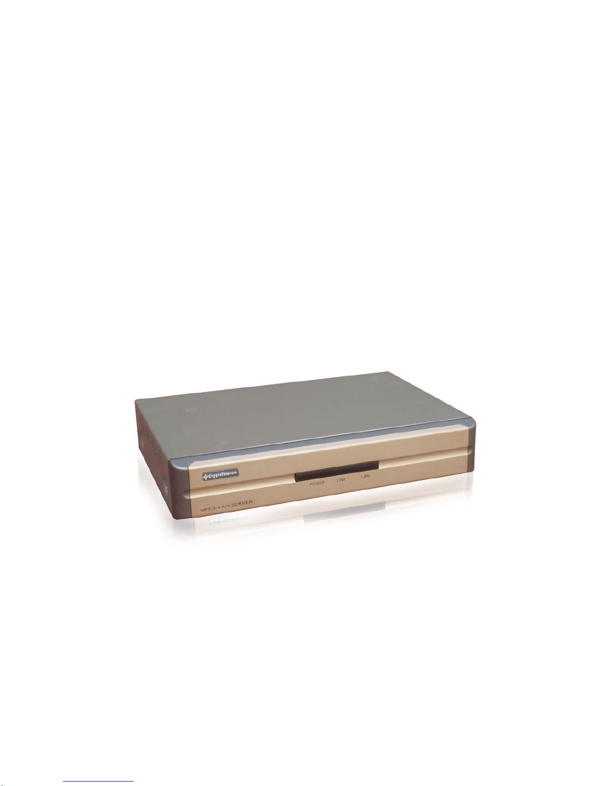
Network A/V Server S-160
User’s Manual
(Version1.0)
Page 2

2
Introduction
¾ The S-160 is a 4 channel video server with a built-in MPEG-4 CODEC and Streaming Server. Th e main
feature of the MPEG-4 CODEC and the built-in Streaming Server allows you to monitor real time images from
remote locations via Internet. S-160 features a Sensor Input, Relay Output, RS232C port that is designed to
control the functions of select pan/tilt/zoom cameras. S-160 supports both Static IP and Dynamic IP, and
can change the Communication Port resulting in one IP address supporting multiple S-160 video servers. In
summary, S-160system provides multiple access/control options to the user.
The examples of access/controls are as follows:
¾ To get SMS message through Mobile Phone and E-mail message from PC when events occur.
¾ To record Event in FTP server installed in remote place or S-160.
¾ To search / delete / down-load / replay the recorded video.
¾ To support various wireless devices such as Mobile Phone, PDA to see real time Video in Wireless Internet
handset.
For more information or inquiry, please contact us to the followings ;
Home Page : www.cryptotelecom.com
E-mail : [email protected]
Tel e p h one ; 82-2-596-1331
Fax : 82-2-596-3707
Address : 5 floor, Seungwon Bldg.,810-9, Bangbae-dong, Seocho-gu, Seoul, 137-064, Korea
Software, Server and service may be charged according to change of policy or may be stopped
without prior notification. Appearance, function and specification may be changed without prior
notification. Our company assumes no
responsibility for visible or invisible loss resulted from
changes in policy or products.
Page 3

3
IMPORTANT NOTES
• Before operating the Vaddio StreamVIEW, please read the entire manual thoroughly. The system was
designed, built and tested for use indoors, and with the provided power supply and cabling. The use of a
power supply other than the one provided or outdoor operation has not been tested and could damage the
unit and/or create a potentially unsafe operating condition.
• Do not operate the S-160if the unit has been dropped or damaged. In this case, a Vaddio technician must
examine the product before operating.
• To reduce the risk of electric shock, do not immerse in water or other liquids and avoid extremely humid
conditions.
• Do not attempt to take the S-160 apart. There are no user-serviceable components inside.
• Do not use this product in connection with life safety or life monitoring related devices, i.e., medical
apparatus.
• Do not operate the S-160under the following conditions for any circumstance:
• Temperatures ab ove 40°C (104°F)
• Temperatures below 0°C (32°F)
• High humidity, condensing or wet environments
• Dusty environments
• In inclement weather or under severe vibration
Page 4

4
Contents
1. FEATURE …………………………………………………………………………….………7
1.1.UNPACKING…………………………………………………………………………………………..……….…7
1.2.
EXTERNAL VIEW……………………………………………………………………………………..……..…...7
1.2.1.Front view …………………………………………………………. …………………………………………...7
1.2.2.Rear view ………………………………………………………. ………………………...………… …..……...8
2. INSTALLATION AND VIDEO CHECK……………………………………………………10
2.1.INSTALLATION…………………………………………………………………………………………….….…10
2.2.V
IDEO CHECK…………………………………………………………………………………….……………10
3. BASIC SETTING……………………………………………………………………………16
3.1.CHECK NETWORK AND INSTALLATION TYPE……………………………………………………….….………16
3.2.I
NSTALLATION WITHOUT IP SHARING DEVICE (ROUTER)……………………………………………..……….16
3.2.1.Static IP Setup………………………………………………………………………………………….………..16
3.2.2.Dynamic IP Setup………………………………………………………………..………………….……..……20
3.3.INSTALLATION WITH IP SHARING DEVICE (ROUTER)……………………………………………….………...22
3.4.C
AUTIONS…………………………………………………………………………………………….……….26
4. EXPERT SETTING…………………………………………………………………………28
4.1.GENERAL SETTING……………………………………………………………………………………..……..30
4.1.1.Title Setting…………………………………………………………………… …………..……..……...………30
4.1.2.Administrator’s ID and Password Change………………………………………………..………………….31
4.1.3.User Registration…………………………………………………………………………………….…………31
4.1.4.User List and Delete…………………………………………………………………………………...……….31
4.1.5.Skip Login (Automatic Monitoring) ………………………………………………………….….…………..32
4.1.6.Time Zone Setting ……………………………………………………………………………..………………32
4.1.7.Set Download Route of Plug-in Type ActiveX……………………………………..………………………...33
4.1.8.Select Language………………………………………………………………………………..………..……..33
4.2.NETWORK SETTING……………………………………………………………………………….…….……33
4.3.V
IDEO & AUDIO SETTING……………………………………………………………………………..………34
4.3.1.Video Setting…………………………………………………….……………………….……………………..34
4.3.2.Audio Setting…………………………………………………………….…………………………….………..37
4.4.COLOR SETTING……………………………………………………………………..……………………….38
4.5.A
LARM SETTING………………………………………………………………………………..…………….39
4.5.1.Alarm Event Setting……………………………………………………………………………..……………..39
4.5.2.Alarm Event Test…………………………………………………………………..…………..……………….40
4.6.DIO SETTING……………………………………………………………………………………..………….41
4.7.RS232C
SETTING………………………………………………………………………………..………….42
4.8.P
RESET SETTING………………………………………………………………………………….………...44
Page 5

5
4.9.HOMEPAGE UPDATE………………………………………………………………………………………...45
4.10.F
IRMWARE UPDATE……………………………………………………………………………….….……45
4.10.1.Remote Upgrade………………………………………………………………………………...….………45
4.10.2.System Re-booting………………………………………………………..…………………..……………47
5. BASIC USE………………………………………………………………….……………49
5.1.USE OF WEB VIEWER…………………………………………………………………….………………..49
5.2.U
SE OF IP SETTING UTILITY……………………………………………………………….………………51
5.3.U
SE OF PIMA SERVER…………………………………………………………………….………………54
5.3.1.User Registration………………………………………………………….………………..……………….54
5.3.2.Camera Registration…………………………………………..……………………….……..…………….57
5.3.3.List of Camera………………………………………………………………………….……….…………...58
5.3.4.Change of User’s Information…………………………………………………………………….………..60
5.3.5. Search Camera………………………………………………….……………..………………….……….61
5.4.USE OF RELAY…………………………………………………………………………………….……….62
5.5.U
SE OF SENSOR…………………………………………………………………………………….……..63
5.6.S
EE AND CONTROL OF STILL IMAGE IN MOBILE OR PDA ………………………………………….……..63
5.6.1.WAP2.0 (HTML) …………………………………………………..………………………….……….…….63
5.6.2.PDA(WinCE) ………………………………………………………………………………………...………66
5.7.USE OF PROPRIETARY VIEWER( MPEG4 COMMUNICATOR)……………………………………….…….67
5.7.1.Required Specification of PC and OS…………………………………………………………….…..…..67
5.7.2.Supported O/S…………………………………………………………………………………..…….…….67
5.7.3.Program Installation………………………………………………………………………….…….……….68
5.7.4.Use of Program……………………………………………………..……………….………….…………..71
5.7.4.1.Viewer Screen……………………………………………………………………….….……….…………..………71
5.7.4.2.General Setting Menu …………………………………………………………………………...…………..73
5.7.4.3.S-160 Connection……………………………………………………………………………………….…..………74
5.7.4.4.Play of Recorded File…………………………………………………………………………………….…....……76
5.7.4.5.Use of Pop-up Menu…………………………………………………………………………………….…..….…..77
6. NETWORK ENVIRONMENTS…………………………………………………….…….79
7. APPENDIX………………………………………………………………………….……81
Page 6

6
1. Feature
Page 7
7
1. Feature
1.1 Unpacking
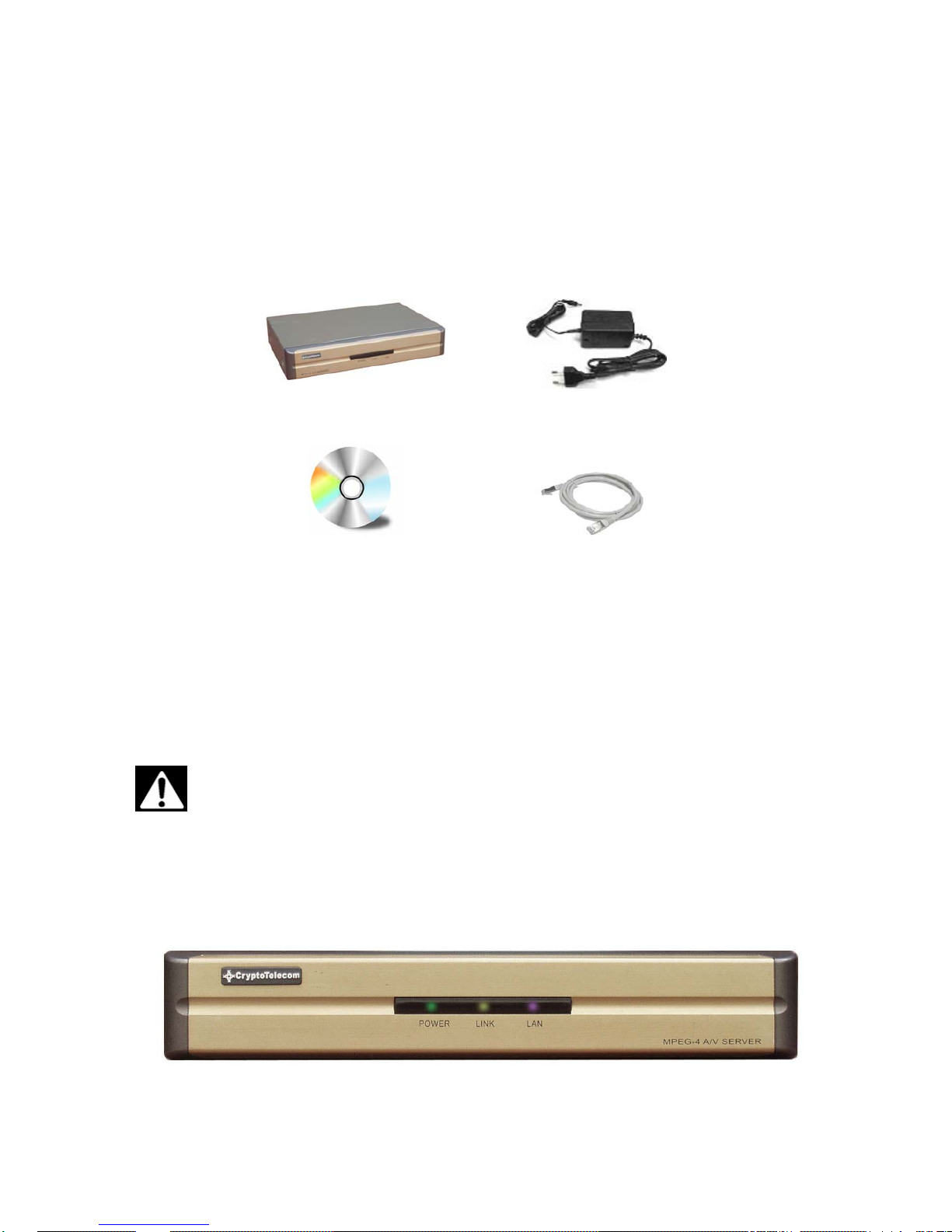
Carefully remove the product and all of the parts from the packaging. Unpack and identify the following parts:
S-160 Power Adapter
Software CD Cross Cable
The content of the packaging includes, S-160 Main Unit, Po wer su pply, User Manual, Software CD, Cross Cable
(for installation only). Please check contents before starting installation. Be sure to use the provided power
supply for the S-160. The Cross Cable is used only for Pre-View of Video before set-up and chang e of Network
Information.
Use only the power supply provided with the S-160 system.
Use of any unauthorized power supply will void any and all warranties.
1.2 External View
1.2.1 Front view
Page 8
8
1) POWER : Light on when power is supplied.
2) LINK : Light on when LAN Cable is connected to S-160.
3) LAN : Light on when connected to Network.
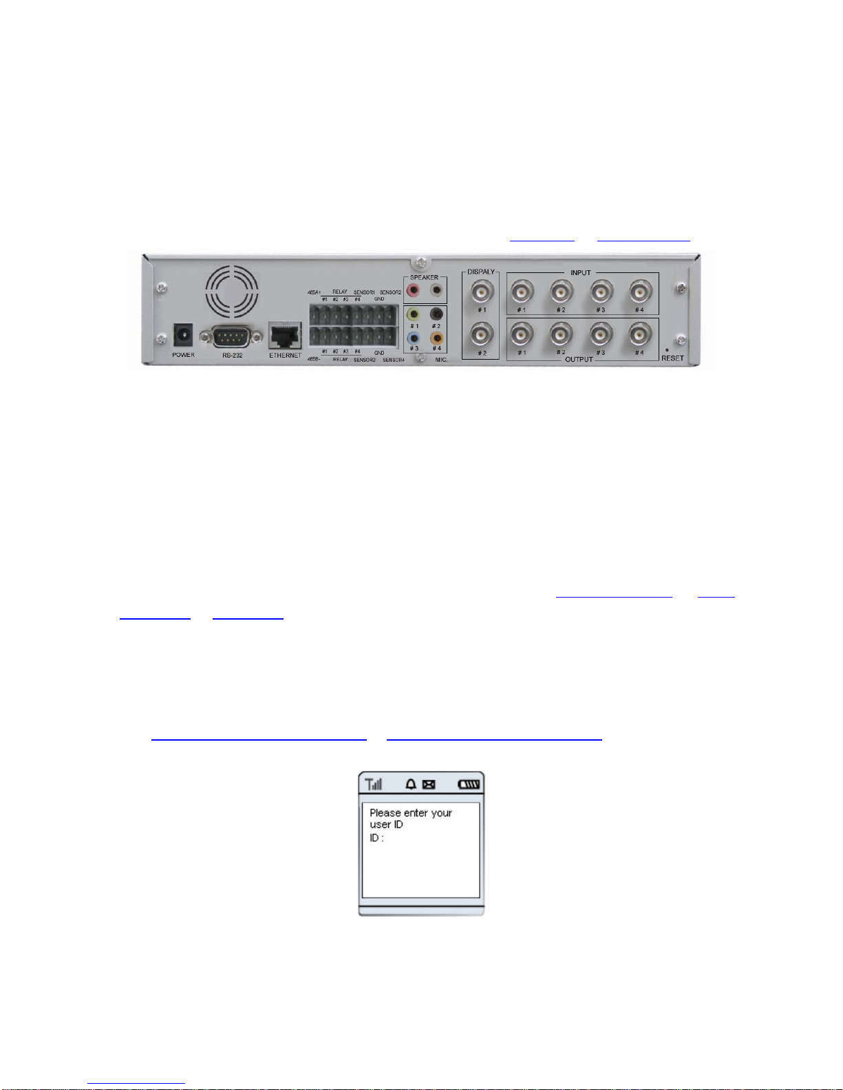
1.2.2 Rear view
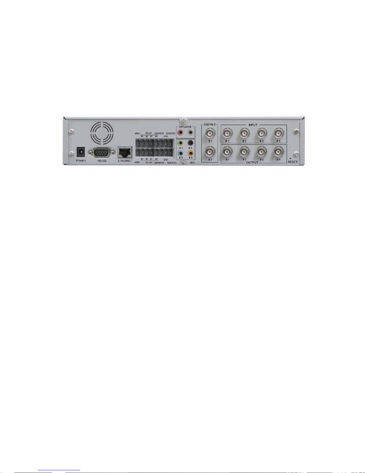
1) Power Supply : Excusive (provided) Adapter only
2) Micro Phone Port : To connect Microphone
3) Speaker Port : To connect Speaker
4) Relay Output : Output port with embedded Relay.
5) Sensor Input : Sensor Input port, to be set in Inner Setting and to be used without regard to N/C or N/O
6) RS485 Port : Input / Output Port of RS485
7) Serial Port : To control of Pan/Tilt/Zoom of Camera and connect to PLC or outer Devices (RS232)
8) Video In : Input port to connect with signal output from Camera, VTR, Quad, DVR
9) Video Out : Output of the same video signal that put into the Video Input Port.
10) LAN : LAN Cable port for Internet to connect to Internet
11) Hardware Reset : To initialize basic setting. Push and hold for seconds to start initialization.
①
②
③④ ⑤⑥
⑦
⑧
⑨
⑩
⑪
⑫
Page 9

9
2. Installation and Video Check
Page 10
10
2. Installation and Video Check
2.1 Installation
On the assumption that User PC and S-160 Sever is used under static IP, and S-160 is to be directly connected
with User PC or Local Network, the installation procedure is to be ;
Pic. 2―1 Rear View
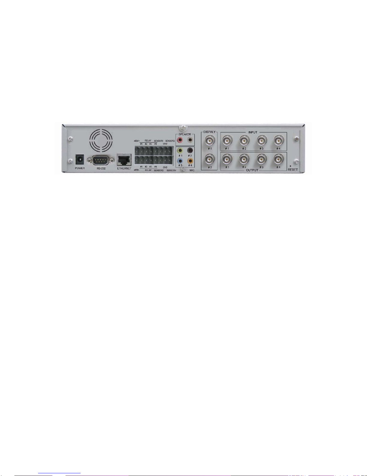
1) Connect Camera and StreamVIEW with Video Cable (8 of [Pic.2-1]).
2) If connecting a Pan/Tilt Camera for control, connect Cable into RS232 Port (7 of [2-1]) or RS485 Port (6 of
[2-1]).
3) Connect StreamVIEW and PC with LAN Cable (Cross Cable) (10 of [2-1])
4) Turn on Camera and StreamVIEW (Use provided power supply only) (1 of [2-1])
5) Wait about 2 minutes after powering up the StreamVIEW, and then the LINK LED shows that the System
has been booted normally.
2.2 Video Check
Basic network setting value of S-160 is to be ;
9 IP Address : 192.168.1.8
9 Subnet Mask : 255.255.255.0
9 Gateway : 192.168.1.1
To connect S-160 in user’s PC, change the setting value of PC network environment.
⑪
①
②
③④ ⑤⑥
⑦
⑧
⑨
⑩
⑪
Page 11
11
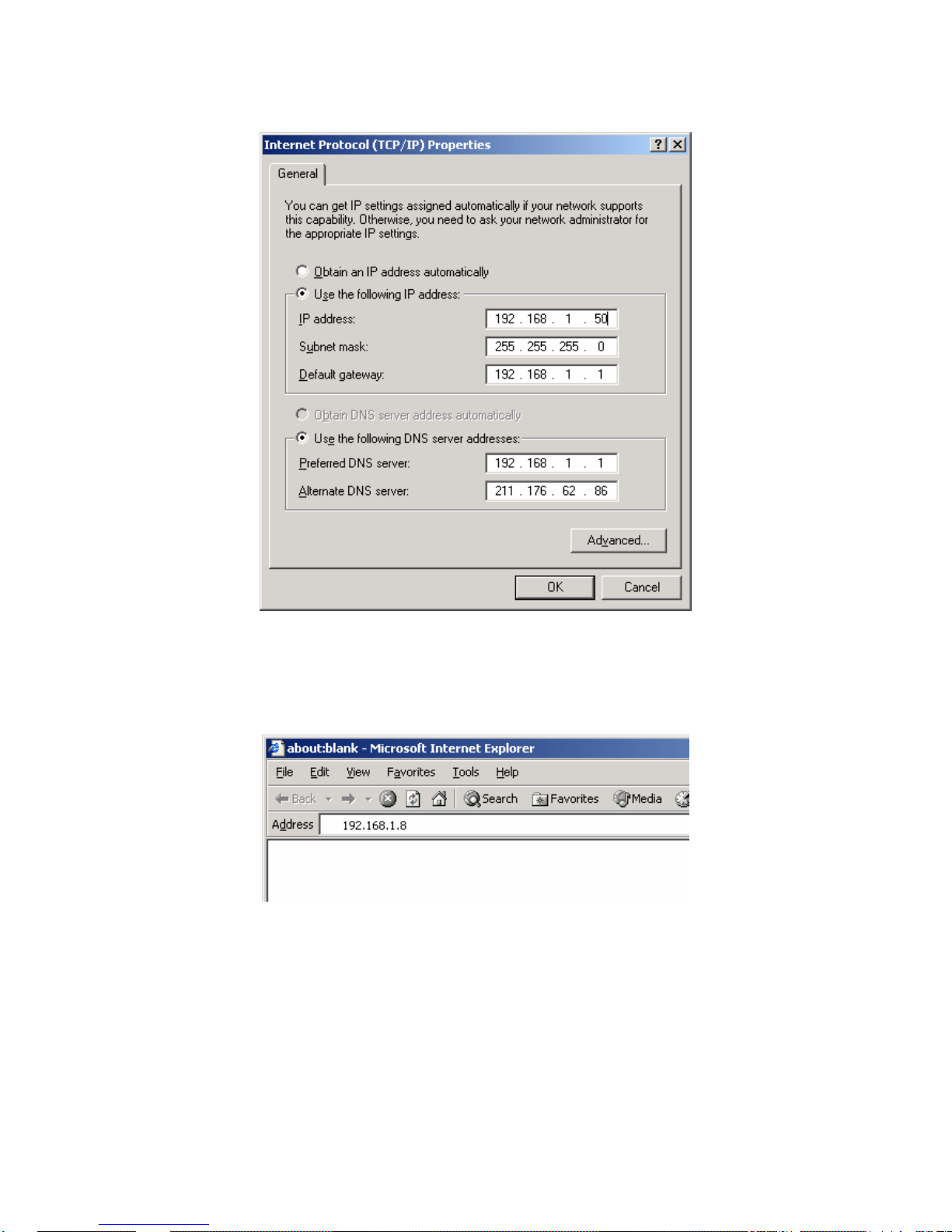
Pic. 2―2 Network Setting of User PC
1) Set IP Address, Subnet Mask and Gate-way of User’s PC with 192.168.1.50, 255.255.255.0 and
192.168.1.1 as shown on [Pic. 2-2].
Pic. 2―3 Web Browser Input
2) Run Web Browser as shown on [Pic. 2-3] and input 192.168.1.8 in URL and click “Enter”, then [Pic. 2-4] is
to be shown. In case [2-4] does not appear, re-set Hardware (Reset Button (6) of Pic. 2-1) to return
Network Environment of S-160 to default and run Web Browser, input 192.168.1.8 in URL line and click
“Enter” .
Page 12
12
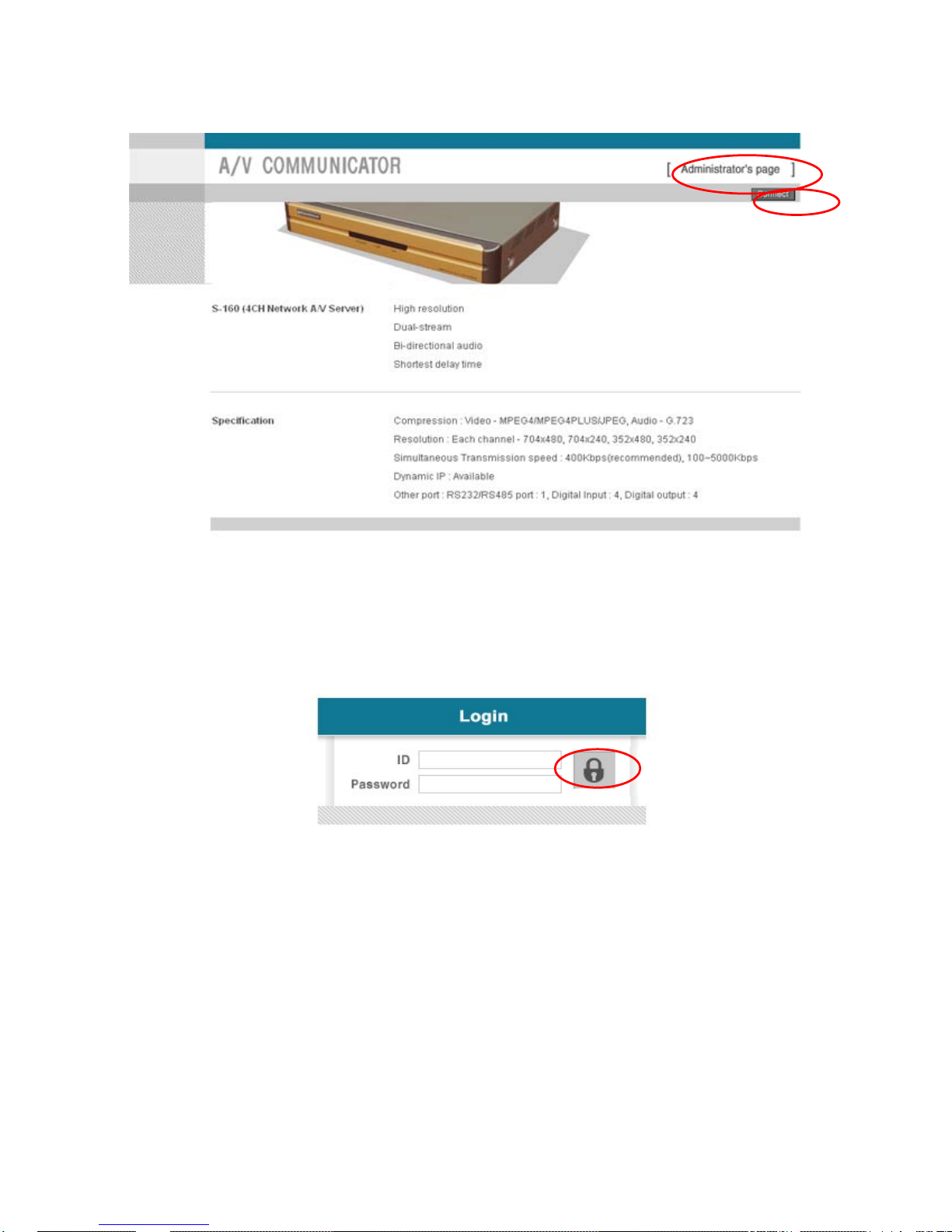
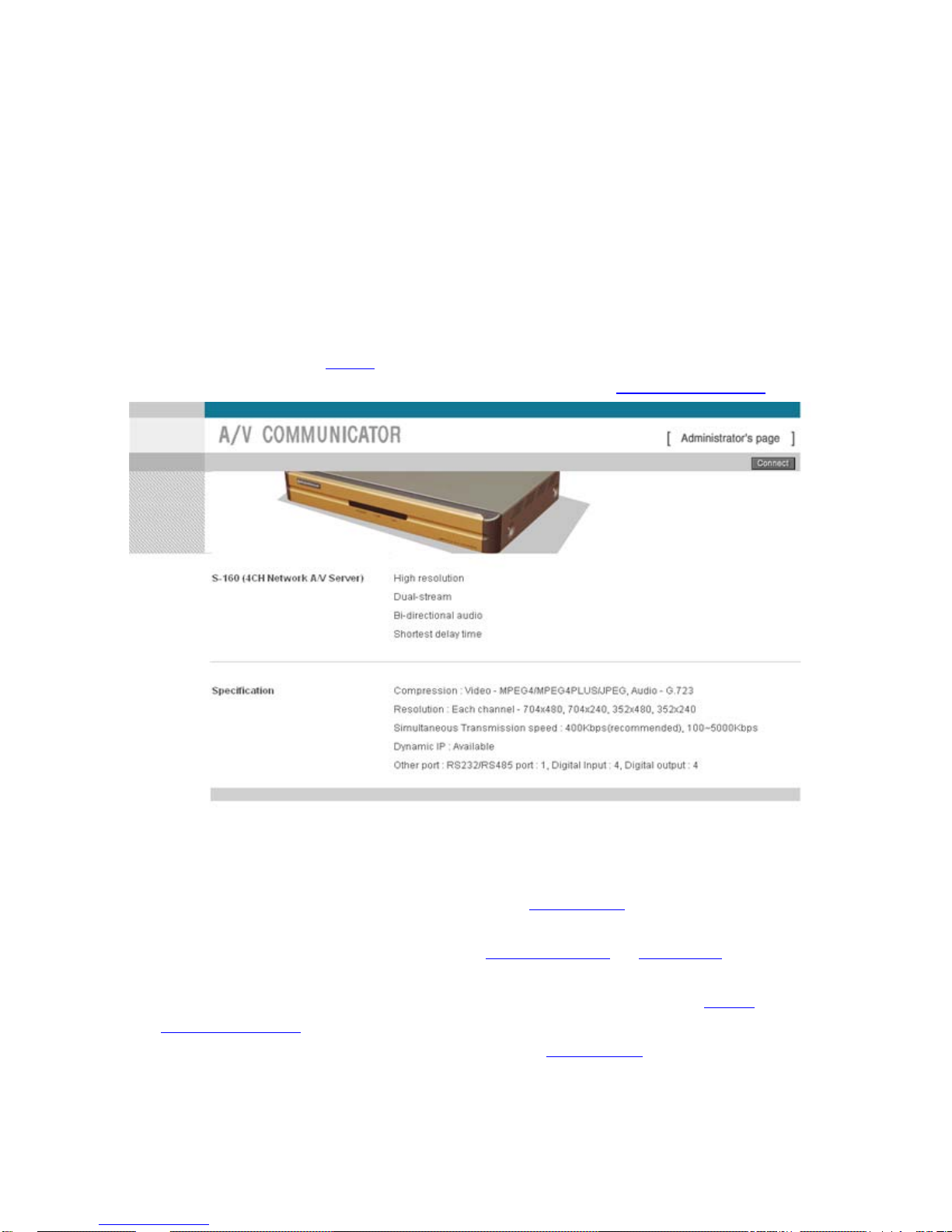
Pic. 2―4 S-160 Main Page
3) Click “Connect” Button of [Pic. 2-4].
Pic. 2―5 User login
4) Input ID and Password and click on the lock [Pic. 2-5] to see the Video feed.
5) User’s Authority to see Video feed on S-160 is as follows ;
Page 13
13
Table 2-1 User ID, Password, Rights
User ID User Password Rights
guest guest Monitor only
ptz ptz Monitor, Control of P/T/Z, Control of Relay
audio audio Monitor, Hearing
Iaudio Iaudio Monitor, Bi-directional Audio
PCAudio PCAudio Monitor, P/T/Z, Relay Control, Hearing (1 way
Audio)
root root All Function
6) Above [Table 2-1] is the value basically set in S-160. Change the User Information in ‘General Setting’ of ‘4.
Expert Setting’ after installation of S-160.
7) Click (1) after input ID:root, Password:root in [2-5].
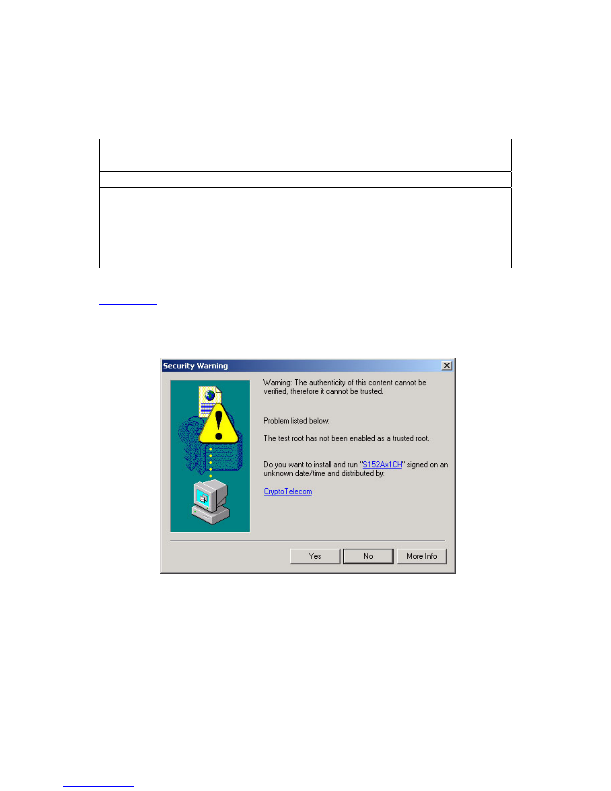
8) Message Window [2-6] appear soon, click ‘Yes’. If click ‘No’, Web Viewer doesn’t work. .
Pic. 2―6 ActiveX Download
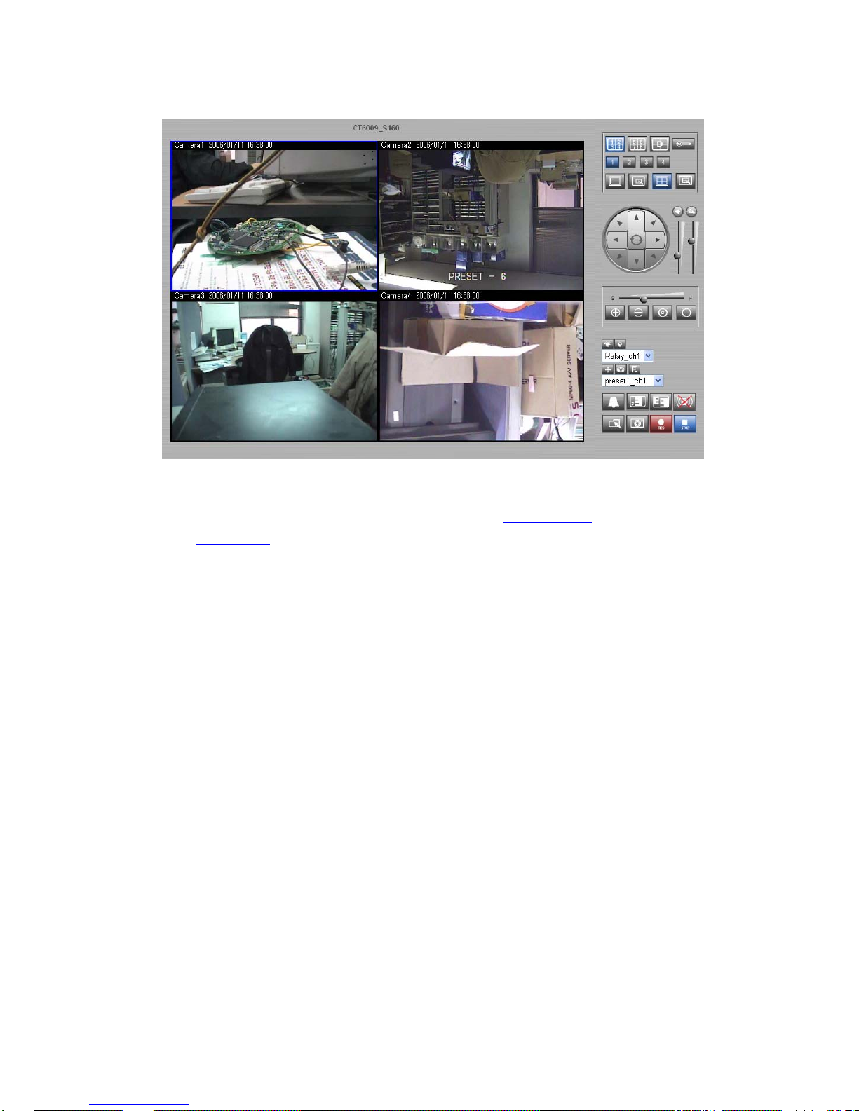
9) Upon installation, Web Viewer [Pic. 2-7] appears and image of Camera is to be seen.
Page 14
14
Pic. 2―7 Web Viewer
10) After checking the video feed [Pic 2-7], go to the next Chapter ‘3. Basic Setting
’
11) Refer to ‘5. Basic Use
’ to see the details how to use Web Viewer.
Page 15

15
3. Basic Setting
Page 16

16
3. Basic Setting
3.1 Check Network and Installation Type
This Chapter is for basic setting of S-160. To install Hardware of S-160, basic understanding of Network is
required. Please refer to Chpater 6 in case knowledge of Network Environment is required.
.
There is two ways to install Hardware,
1. install S-160 without IP sharing Device
under Cable Modem or Leased Line,
2. install S-160 under IP sharing Device
, which is required under PPPoE environment, and even under
Leased Line or Cable Modem. The default IP Address of S-160 is preset to 192.168.1.8 and Subnet Mask to
255.255.255.0 and Gateway to 192.168.1.1 in ex-factory condition. This explanation is based upon default value
of ex-factory.
Caution 1 : Check Video before installation, on ‘2. Installation and Video Check
’.
Caution 2 : In case using IP sharing Device, only Global IP is available.
Caution 3: S-160 does not support PPPoE. IP Sharing Device is required to connect to S-160
under PPPoE.
Installation without IP sharing device
-> For static IP, refer to ‘Static IP Setup
’.
-> For dynamic IP, refer to ’ Dynamic IP Setup
’.
Installation with IP sharing device
-> Should set up with Static IP. Refer to ‘Installation with IP Sharing Device
’.
3.2 Installation without IP sharing device (Router)
3.2.1 Static IP Setup
1) After checking Video in ‘Video Check
’, go to the next step.
2) Connect S-160 to PC with LAN Cable (Cross Cable).
3) Cable connection and Network Setup should be same as shown in ‘1. Installation and Video
Check’.
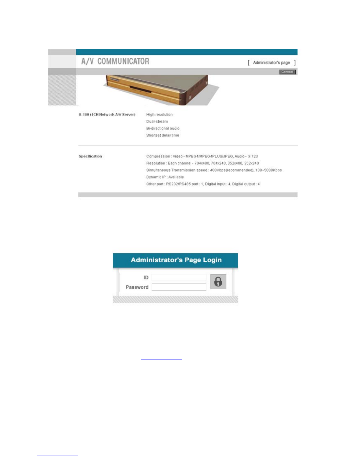
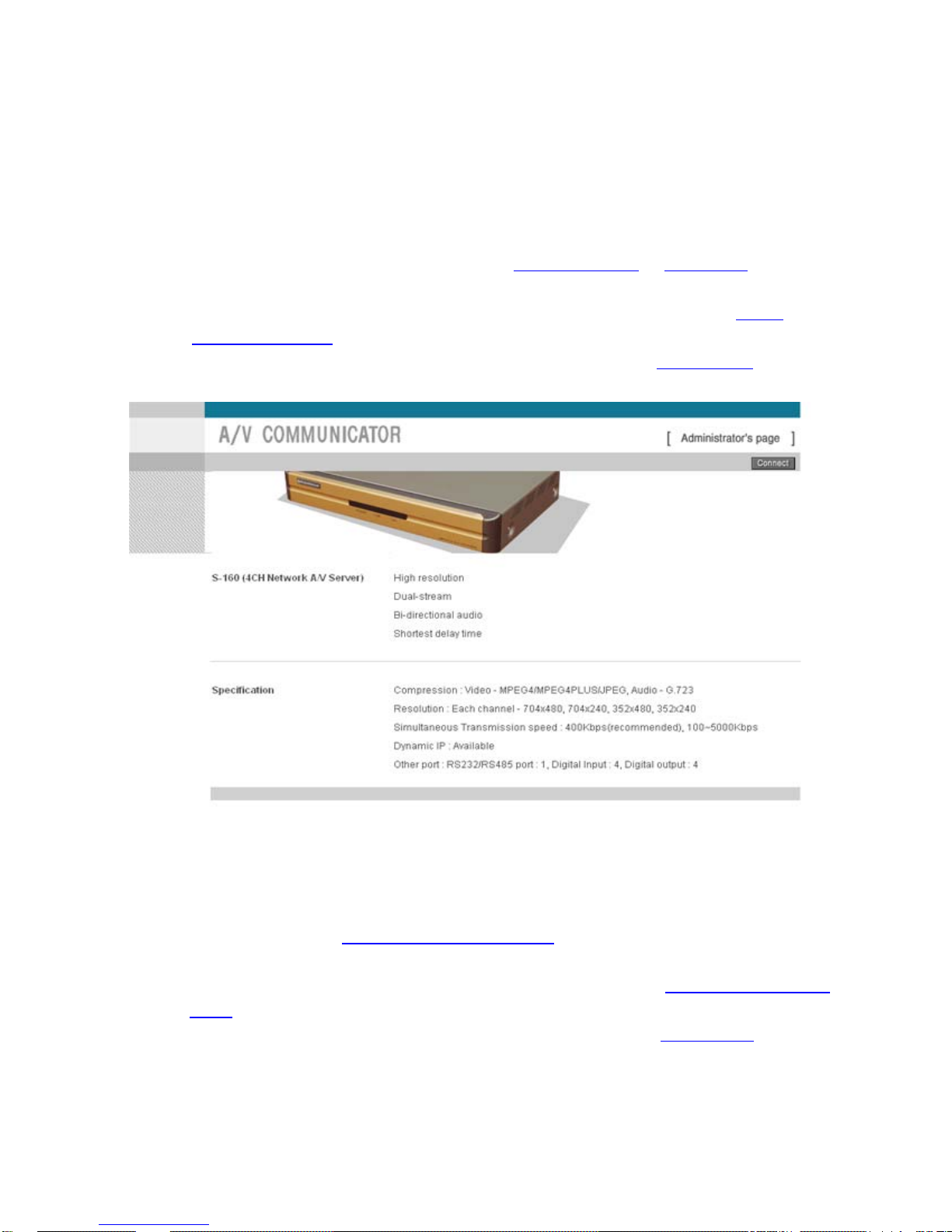
4) Run Web Browser and input 192.168.1.8 in URL and click ‘Enter’, then [Pic. 3-1] will appear.
Page 17
17
Pic. 3―1 Main Page of S-160
5) Click ‘Administrator’s Page’ of [Pic. 3-1], then Browser shows [Pic. 3-2] Log-in Page.
Pic. 3―2 Administrator Page Log-in
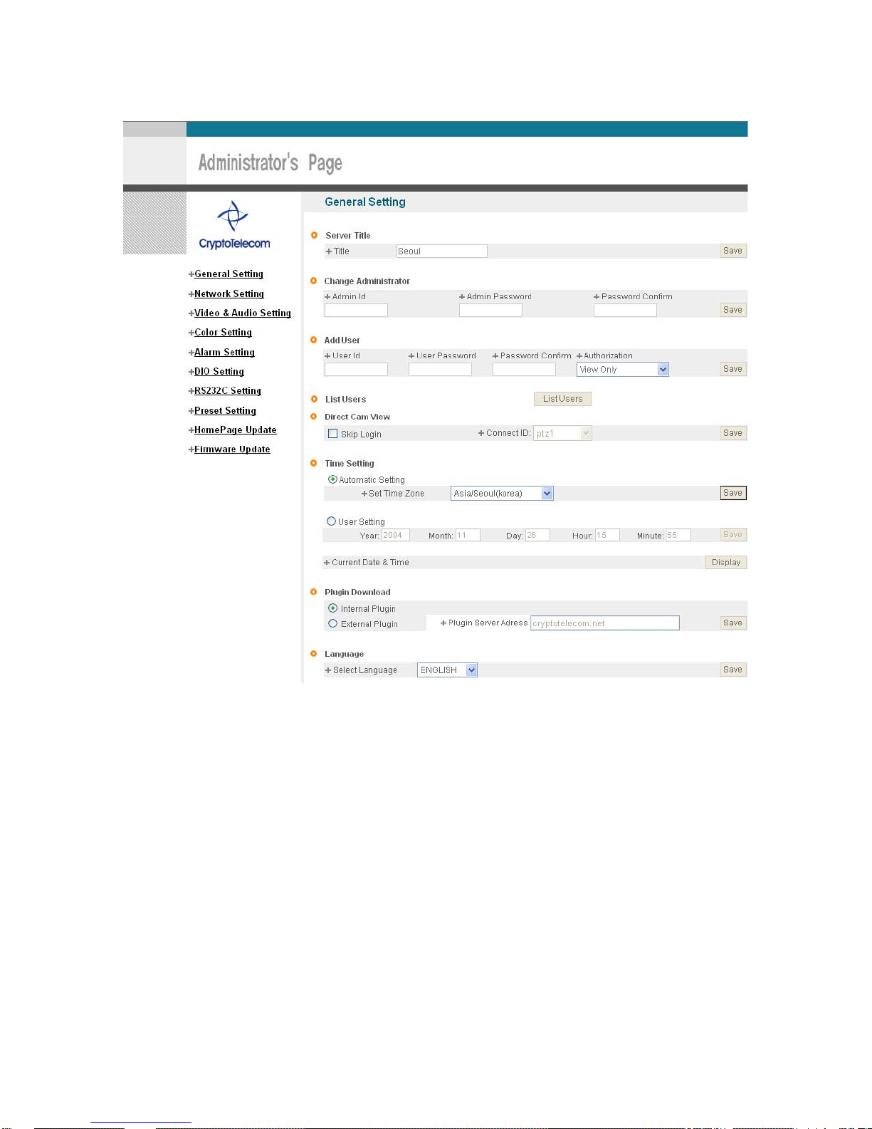
6) Put ‘admin’ in ID and Password line, click ‘Login’, then [Pic.3-3] ‘Administrator's Page’ will be shown. (ID,
Password of S-160 is preset as admin/admin in Administrator’s Page. Change Administrator’s ID and
Password in General Setting of ‘4. Expert Setting’
Page 18
18
Pic. 3―3 Administrator’s Page
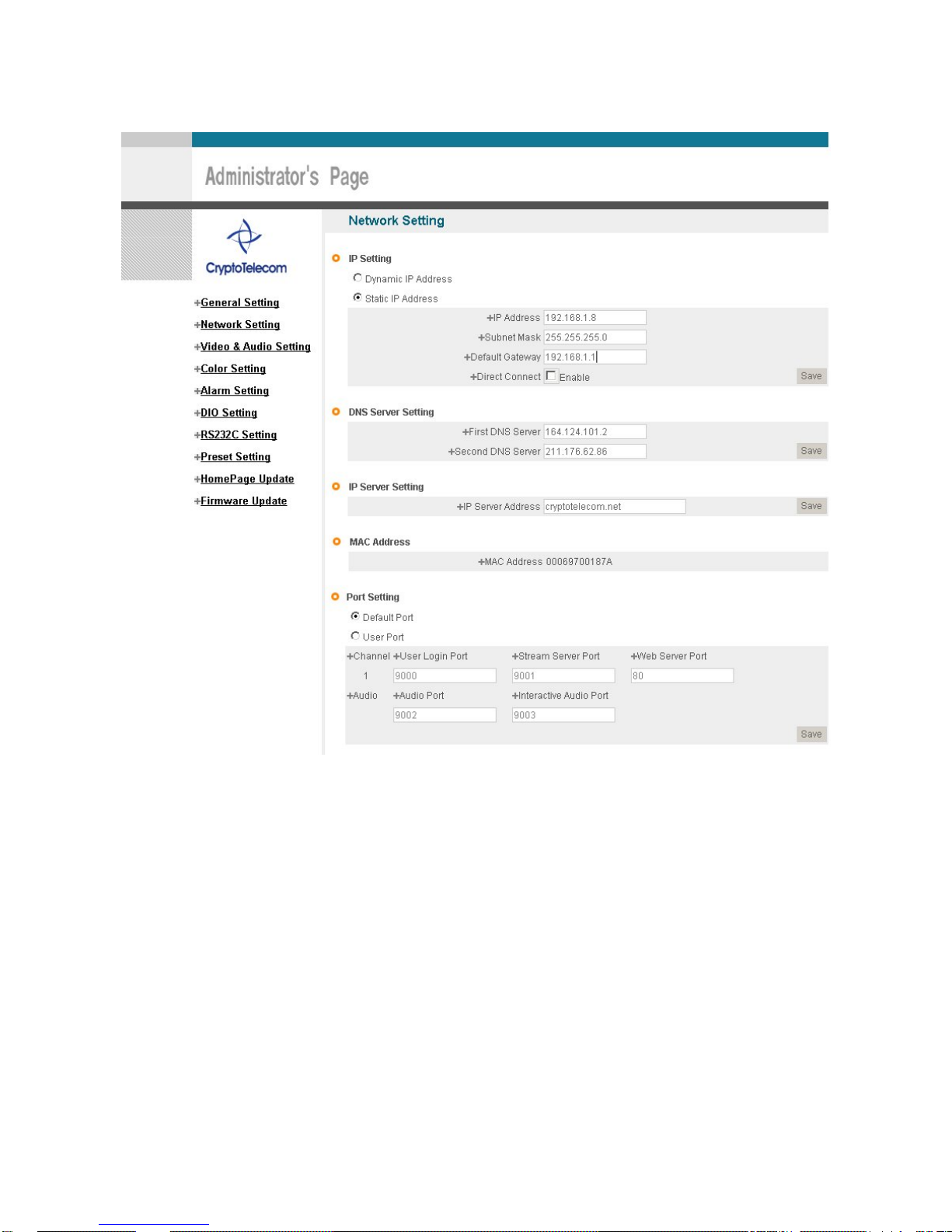
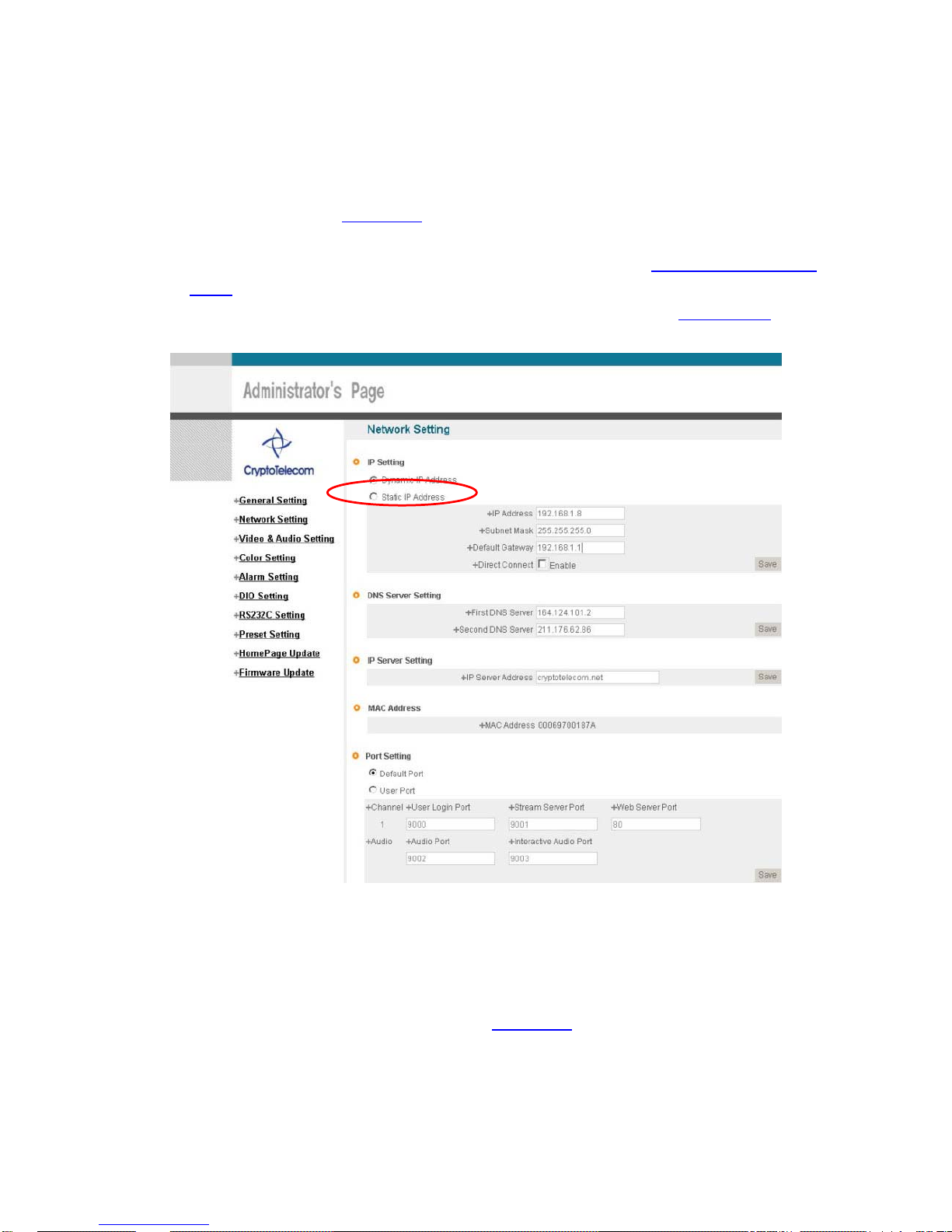
7) Click “Network Setting’ in left menu on [Pic..3-3], [Pic. 3-4] appears.
8) Click ‘Static IP Address’ in ‘IP Setting’ of [Pic. 3-4], and input IP Address, Subnet Mask,
Default Gateway according to Network environment to connected S-160.
9) For setting of ‘DNS Server’, input DNS Address to fit with Network Environment to set.
(Default Address of S-160 is DNS Address of ‘Dacom’, ’Cryptotelecom’). Use
DNS value normally set in PC.
10) DNS Address should be necessarily input.
11) In case of installation without IP sharing device under Static IP, tick on ‘Enable’ of
‘Direct Connect’. The ‘Direct Connect’ option makes direct connection to IP set on Video connection
through Web Viewer. (But not tick ‘Enable' in case of installation under IP Sharing Device.)
12) Click ‘Save’ Button of [3-4] to save setting value.
Page 19
19
Pic. 3―4 Network Setting
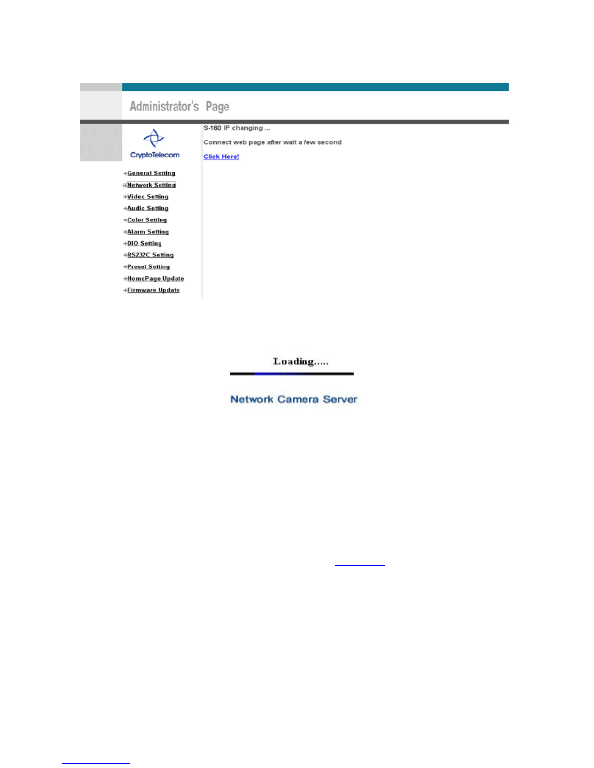
13) Click ‘Click Here’ upon appearing of IP Change Window of [Pic. 3-5].
14) IP Change loading Page appears as [3-6], the Main Page of changed address is connected. (May not
find the main page of changed address under Cross Cable connection, but IP been changed.)
Page 20
20
Pic 3―5 IP Change
Pic. 3―6 IP Change loading Page
15) Remove LAN Cable (Cross Cable) connected between S-160 and PC.
16) Connect S-160 to Network with LAN Cable (Straight Cable).
17) Connect PC to Network with LAN Cable (Straight Cable)..
18) Set up IP Address, Subnet Mask and Gate way of PC according to Network environment.
19) Check
9 Run Web Browser on PC, input IP address set in S-160 onto URL and click ‘Enter’,
9 Check if IP Setting is correct or not, referring to ‘Video Check
’
9 In case Video is seen, S-160 has been correctly set up.
9 In case Vi deo is not se en, check w heth er there may be conf liction of IP in Network, and re-
check the set value of Network environment of S-160, and Network environment of User’s PC.
3.2.2 Dynamic IP Setup
9 Do not set up Dynamic IP in S-160 except direct connection of Cable Modem supporting
Dynamic IP with S-160.
Page 21
21
9 Reset, in case IP has not been allocated to S-160 in Dynamic IP Setting, to go to Initial Value
and try again.
1) After checking Video in ‘Video Check
’, then go to the next step.
2) Connect S-160 and LAN Cable (Cross Cable)
3) Cable Connection and Network Setting should be done same as per‘1. Installation and Video
Check’.
4) Go to Network Setting Page of Administrator’s Page as per 4), 5), 6), 7) of ‘Static IP Setup
’.
Pic. 3―7 Network Setting
5) Click on ‘Dynamic IP Address’ in ‘IP Setting’.
6) Click ‘Save’ Button.
7) Upon completion of setting, close the Web Page and find IP of S-160 in ‘IP Utility’
program provided with Proprietary Viewer (see ‘5. Basic Use
’)
8) If IP found, S-160 has been given IP. But in case IP is not found, do re-set of [2-1] to go to initial
value because it has not been given IP, then re-start IP Setting. Once S-160 is given IP, remove LAN
Page 22
22
Cable (Cross Cable) connected between S-160 and PC.
9) Connect S-160 to Network with LAN Cable (Straight Cable).
10) Connect PC to Network with LAN Cable (Straight Cable).
11) Set IP address of PC, Subnet Mask and Gateway properly according to Network Environment.
12) Check
After registration of S-160 in PIMA Server (refer to ‘Use of PIMA Server
’ of ‘ 5. Basic Use’,
connect to S-160 by Domain Name (Server Name) allocated to S-160.
For example, run Web Browser and input Domain Name allocated to S-160 in URL. In http://s-
160.cryptotelecom.net, ‘S-160’ is to be Name of Server registered in PIMA Server by user.
If the initial page is shown as [Pic. 3-8], check Video of S-160 referring to ‘1. Video Check
’. If Video
is seen, set up is properly done.
Pic. 3―8 Initial Page of S-160
3.3 Installation with IP Sharing Device (Router)
1) After checking Video in ‘ 1. Installation and Video Check’, then go to the next step.
2) Connect S-160 and PC w ith LAN Cable (Cross Cable).
3) Cable Connection and Network Setting should be done same as per ‘1. Installation and Video
Check’.
4) Go to Network Setting Page of Administrator’s Page as per 4), 5), 6), 7) of ‘Static IP Setup
’.
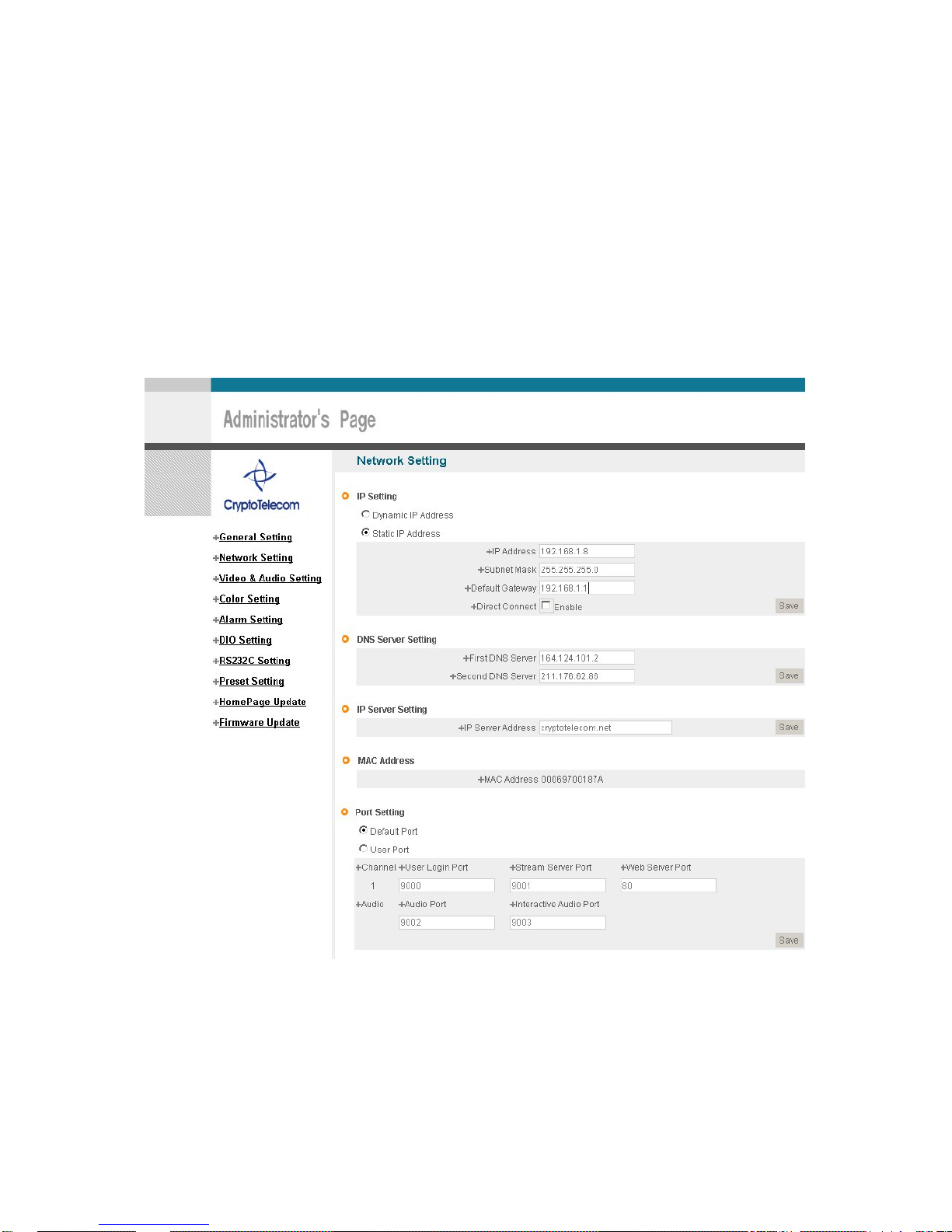
5) Click ‘Static IP Address’ in ‘IP Setting’ of [3-9], and input IP Address, Subnet Mask, Default Gateway
according to Network environment to connected S-160 to.
Page 23
23
6) For setting of ‘DNS Server’, input DNS Address to fit with Network Environment to set.
(Default Address of S-160 is DNS Address of ‘KTF’,’Hanaro Communication’). Use
DNS value normally set in PC.
7) DNS Address should be input surely. In case S-160 is installed under IP Sharing Device, input local IP
of Router in 2
nd
DNS Server Address.
8) In case of installation without IP sharing device under Static IP, ti ck on ‘Enable’ of ‘Direct Connect’.
The ‘Direct Connect’ option makes direct connection to IP set on
Video connection through Web Viewer. (But not tick ‘Enable' in case of installation under IP Sharing
Device.)
9) Click ‘Save’ Button of [3-9] to save the set value.
Pic. 3―9 Network Setting
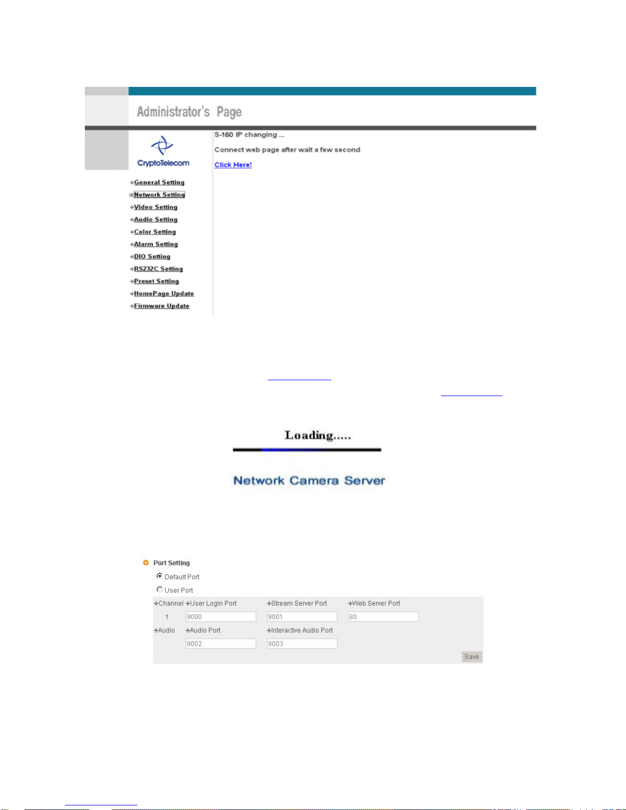
10) Click ‘Click Here’ upon appearing of IP Cha nge Window of [Pic. 3-10].
11) IP Change loading Page appears as [3-11], the Main Page of changed address is connected. (may
not find the main page of changed address under Cross Cable connection, but IP has been changed.)
Page 24
24
Pic. 3―10 IP Change
12) It is connected to IP newly set up, in 20 seconds after window of [3-11] appears.
13) Check Video of S-160 referring to ‘1. Video Check
’ as soon as it is connected to IP newly set up.
14) Go to Network Setting Page of Administrator’s Page as per 4), 5), 6), 7) of ‘Static IP Setup
’.
Pic. 3―11 IP Change loading Page
Pic. 3―12 Port Setting
15) Set Port in Port Setting Page of [Pic.3-12]. It is required to set each different Port for many S-160
Page 25
25
Servers under 1 Router.
16) Click ‘Save’ Button to save set value.
17) Remove LAN Cable (Cross Cable) connected between S-160 and PC.
18) Connect S-160 to Network with LAN Cable (Straight Cable).
19) Connect PC to Network with LAN Cable (Straight Cable).
20) Port-Forward the port designated to use S-160, in IP Sharing Device. Refer to manual of IP Sharing
Device for details.
21) Check 1 (local check)
Run Web Browser and input IP address of S-160 in URL and click ‘Enter’. If you changed Web Server
Port, you must input ‘http://IP
Address:Port Number’. For example, If you set IP address of S-160 to
192.168.0.100 and changed Web Server port to 81, you must input Http://192.168.1.100:81
.
Pic. 3―13 Main Page of S-160
After [Pic.3-13] appears, check Video of S-160 referring to‘1. Video Check
’.
22) Check 2 (Check from outside)
After registration of S-160 in PIMA Server (refer to ‘‘Use of PIMA Server
’ of ‘‘ 5. Basic Use’,
connect to S-160 by Domain Name (Server Name) allocated to S-151.
For example, run Web Browser and input Domain Name allocated to S-160 in URL. In http://S-
151.cryptotelecom.net , ‘S-160’ is to be Name of Server registered in PIMA Server by user.
If the initial page is shown, check Video of S-160 referring to ‘1. Video Check
’. If Video is seen, set up is
properly done.
Page 26

26
3.4 Cautions
If the firewall is used for security purpose, S-160 may not work properly. In this case, open
the port of S-160, then it will work properly. The port being used by S-160 can be checked
on ‘Port Setting’ of ‘Network Setting’ of ‘Administrator’s Page’.
Port of S-160 on ex-factory is set default as follows ;
¾ Web Connection Port : Port 80 TCP
¾ Authentication and Control Port: Port 9000 TCP
¾ Video Streaming Port : Port 9001 TCP
¾ Audio one-way Port : Port 9002 TCP
¾ Audio two-way Port : Port 9003 TCP
In setting user port, do not use 1504, 1508, which port is used in S-160 itself.
Page 27

27
4. Expert Setting
Page 28
28
4. Expert Setting
After registration of S-160 in PIMA Server (refer to ‘Use of PIMA Server’ of ‘‘ 5. Basic Use’’,
connect to S-160 by Domain Name (Server Name) allocated to S-160. (For example, run Web Browser
and input Domain Name allocated to S-160 in URL. In http://s-160.cryptotelecom.net
, ‘S-160’ is to be
Name of Server registered in PIMA Server by user)
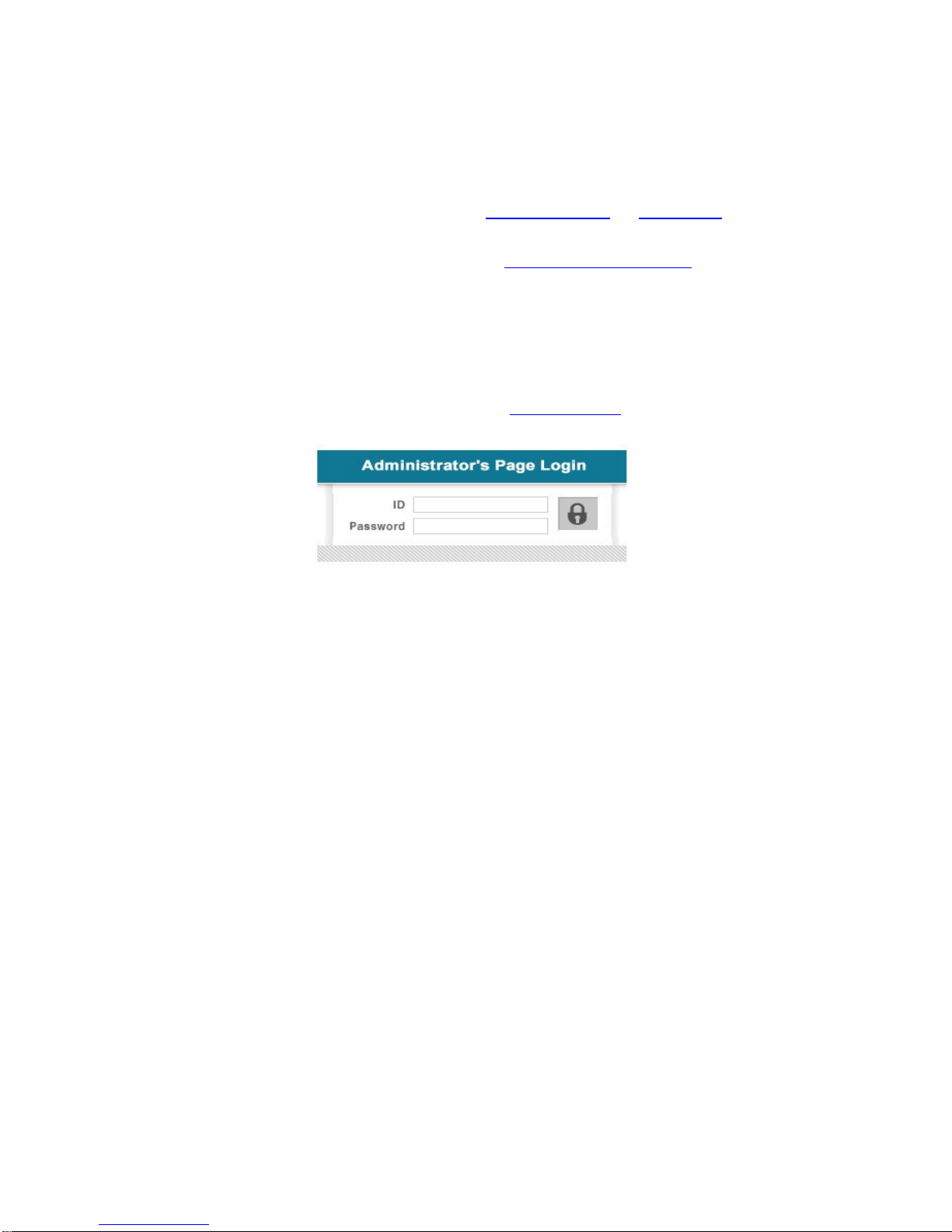
Click ‘Administrator’s Page’ on Initial Page of S-160, login Page of [Pic.4-1] appears.
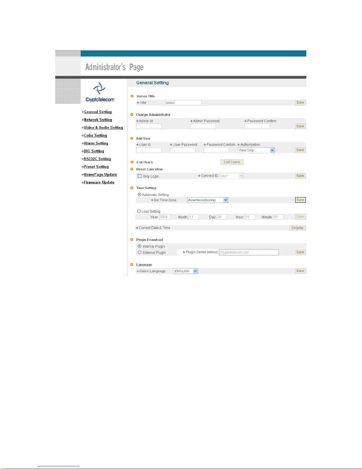
Put ‘admin’ in ID and Password line, click ‘Login’, then [Pic.4-2] ‘Administrator's Page’ will be
shown. (ID, Password of S-160 is preset as admin/admin in Admini s t ra tor’s Page. Chan ge
ID and Password of Administrator in General Setting of ‘4. Expert Setting’
. )
Pic. 4―1 Administrator’s Page Login
Page 29
29
Pic. 4―2 Administrator’s Page
Page 30
30
4.1 General Setting
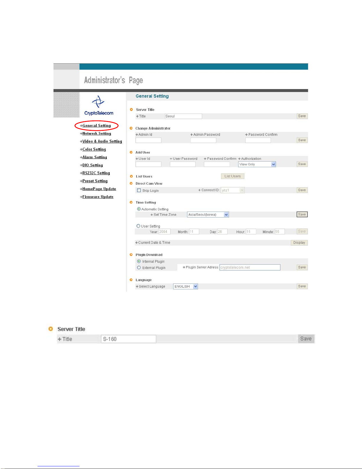
Pic. 4―3 General Setting
4.1.1 Title Setting
Pic. 4―4 Title Setting
Server title is to be English without space.
Click ‘Save’ Button to save title after input name.
Page 31
31
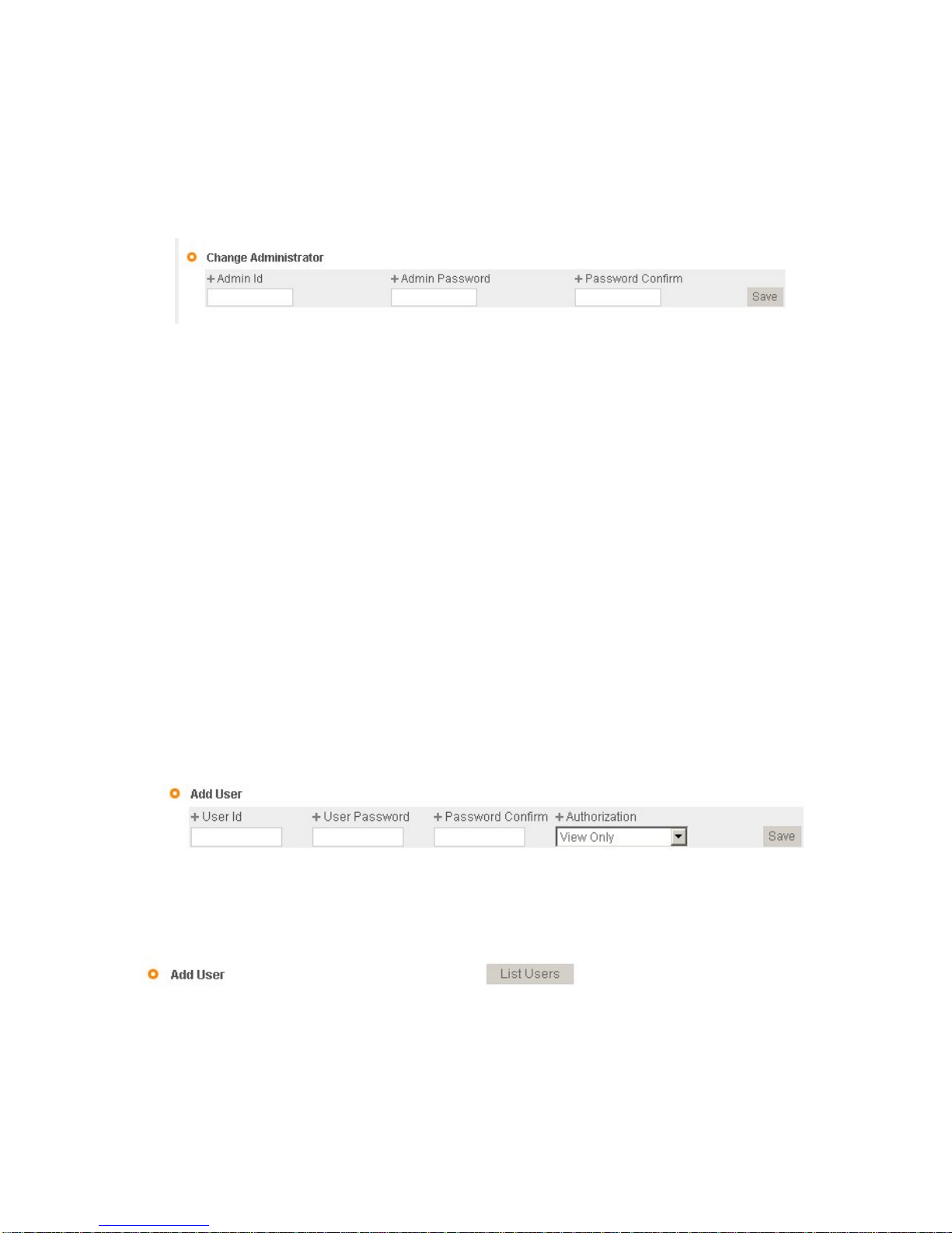
4.1.2 Administrator’s ID and Password Change
※ Cautions : Change Administrator’s ID and Password and do not disclose the information to others.
Administrator’s ID and Password should be English, within 20 characters, without space.
Click ‘Save’ Button to save the changed value after change Administrator’s ID and Password.
Pic. 4―5 Administrator’s ID and Password Change
Remember Administrator’s ID and Password. In case of forgetting Administrator’s ID and
Password, click ‘reset’ button for returning to initial value, and change Administrator’s ID
and Password.
4.1.3 User Registration
This is to register an account of user who monitor and control Video of S-160.
Administrator’s ID and Password should be English, within 20 characters, without space. Allow the authority to
users and click ‘Save’ button. A maximum user to allow registration is 100 persons.
¾ V iew Only : Monitoring only.
¾ PTZ+Control : Monitoring, Control of P/T/Z of Camera and Relay.
¾ Audio : Monitoring, and hearing Audio of Server.
¾ Interactive Audio : : Monitoring, Two-way Audio Communication with Camera Server
¾ PTZ+Control+Audio : M onitoring, Control of P/T/Z of Camera and Relay, Hearing Audio of Camera
Server.
¾ All : Monitoring, Control of Camera P/T/Z and Relay, two-way Audio Communication with Camera
Server, (Preset available)
Pic. 4―6 User Registration
4.1.4 User List and Delete
Pic. 4―7 User List
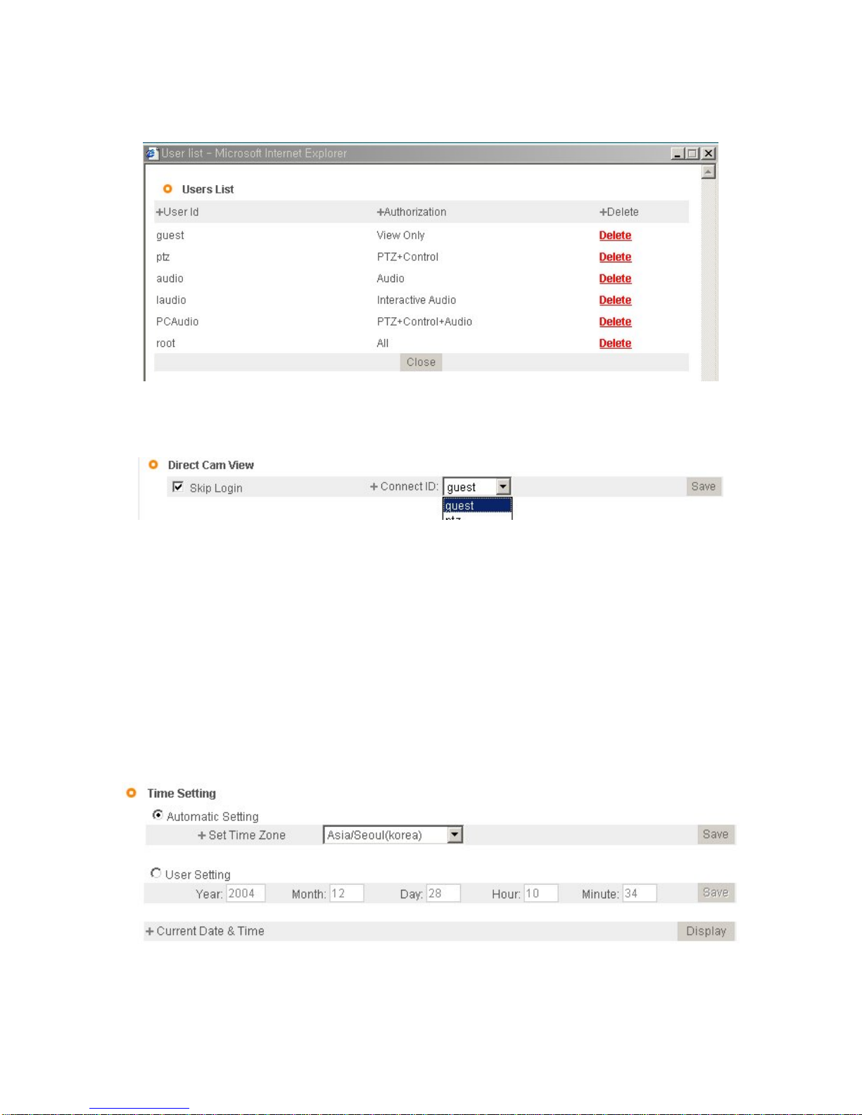
User list is available on clicking ‘List Users’ on [Pic.4-7], to chec k list and delete user ID in [Pic.4-8].
User ID ‘guest’, ‘ptz’, ‘audio’, ‘Iaudio’, ‘PCAudio’, ‘root’ has be pre-registered as basic user
Page 32
32
ID on ex-factory.
Pic. 4―8 User List
4.1.5 Skip Login (Automatic Monitoring)
Pic. 4―9 Skip Login
Check on ‘Skip Login’ of [Pic.4-9], and click ‘Connect ID’ and save the value, then Web Viewer will
be appeared automatically and Video of Camera can be seen upon connection to Home Page of S-160.
Save ‘Connect ID’ according to user authority. If you don’t check on ‘Skip Login’, it is available to connect to S160 Home Page but you can not see the Video feed from the camera. In this case, input user ID and Password
for connection to see the Video feed from the Camera.
4.1.6 Time Zone Setting
This is to set Time zone of location where S-160 is to be installed, to set up local time in case of monitoring
from different time zone area. Select one of time zone in ‘Set Time Zone’ and save.
Pic. 4―10 Time Zone
Page 33
33
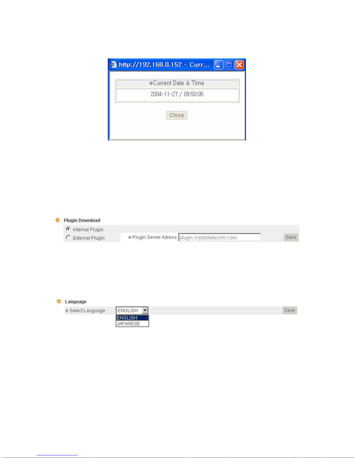
Click ‘Display’ in [4-10] to see current time set in S-160.
Pic. 4―11 C urre nt Ti me View
In case S-160 does not keep correct time, click ‘Update’ Button to get new time information from set time zone.
4.1.7 Set Download Route of Plug-in Type ActiveX
This is to set how to download Active X of Web Viewer, locally or from outer Server designated. In case setting
as local download, it has a merit to use in private network without Internet. In case of setting as download from
outside, it has a merit to download the updated Active X of Web Viewer automatically.
Pic. 4―12 Plug-in Download Route
4.1.8 Select Language
This is to select language to be displayed in all Web Pages such as Administrator’s Page, Web Viewer and
Main Page of S-160.
Pic. 4―13 Select Language
It supports both English and Japanese. Click ‘Save’ Button to save the set value after select the Language.
Input ID and Password to connect Administrator’s Page, and go to ‘Home Page Update’->’Default Home
Page Setting’->’Default’, and change the main Page and Login Page of S-160 to the selected language.
4.2 Network Setting
This is to set Network to use S-160. Set Network to fit user’s network environment in
Page 34
34
‘3. Basic Setting ’. Change Network information to fit environment for S-160 to be installed in.
4.3 Video & Audio Setting
4.3.1 Video Setting
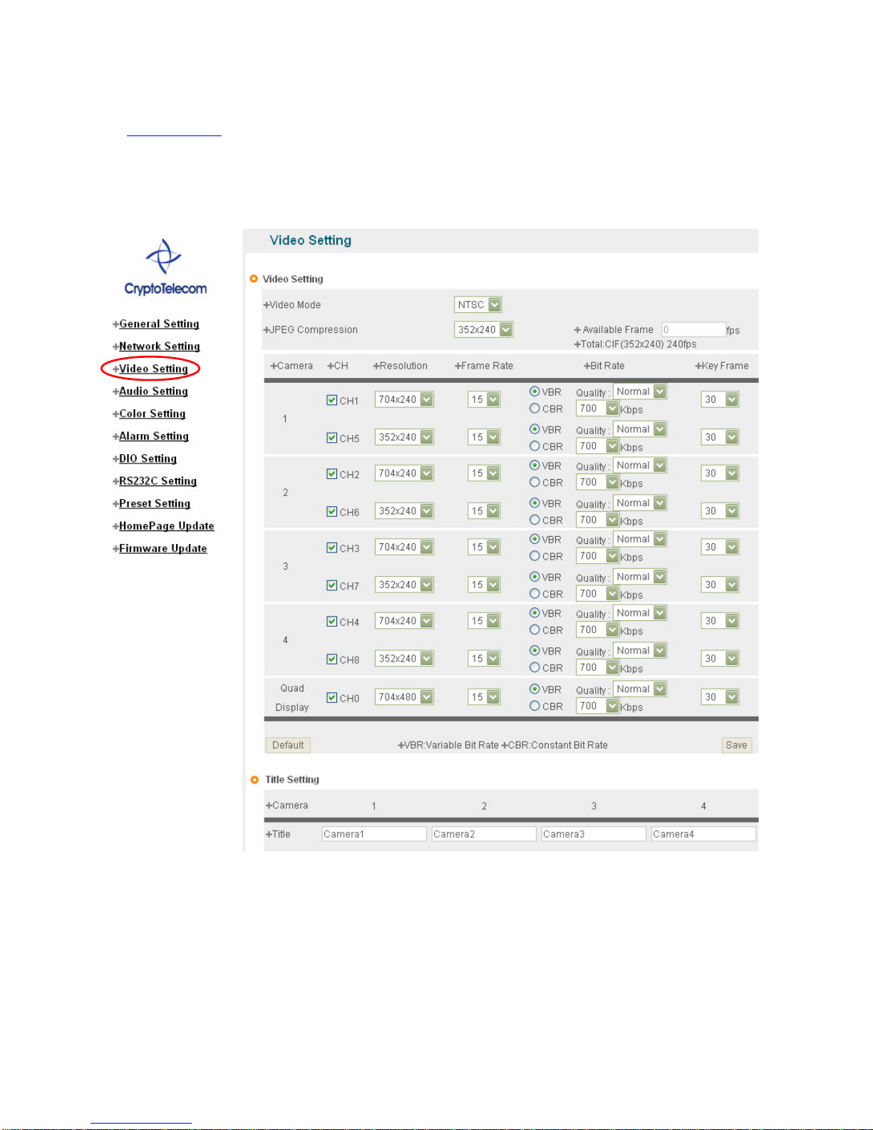
Pic. 4―14 Video Setting
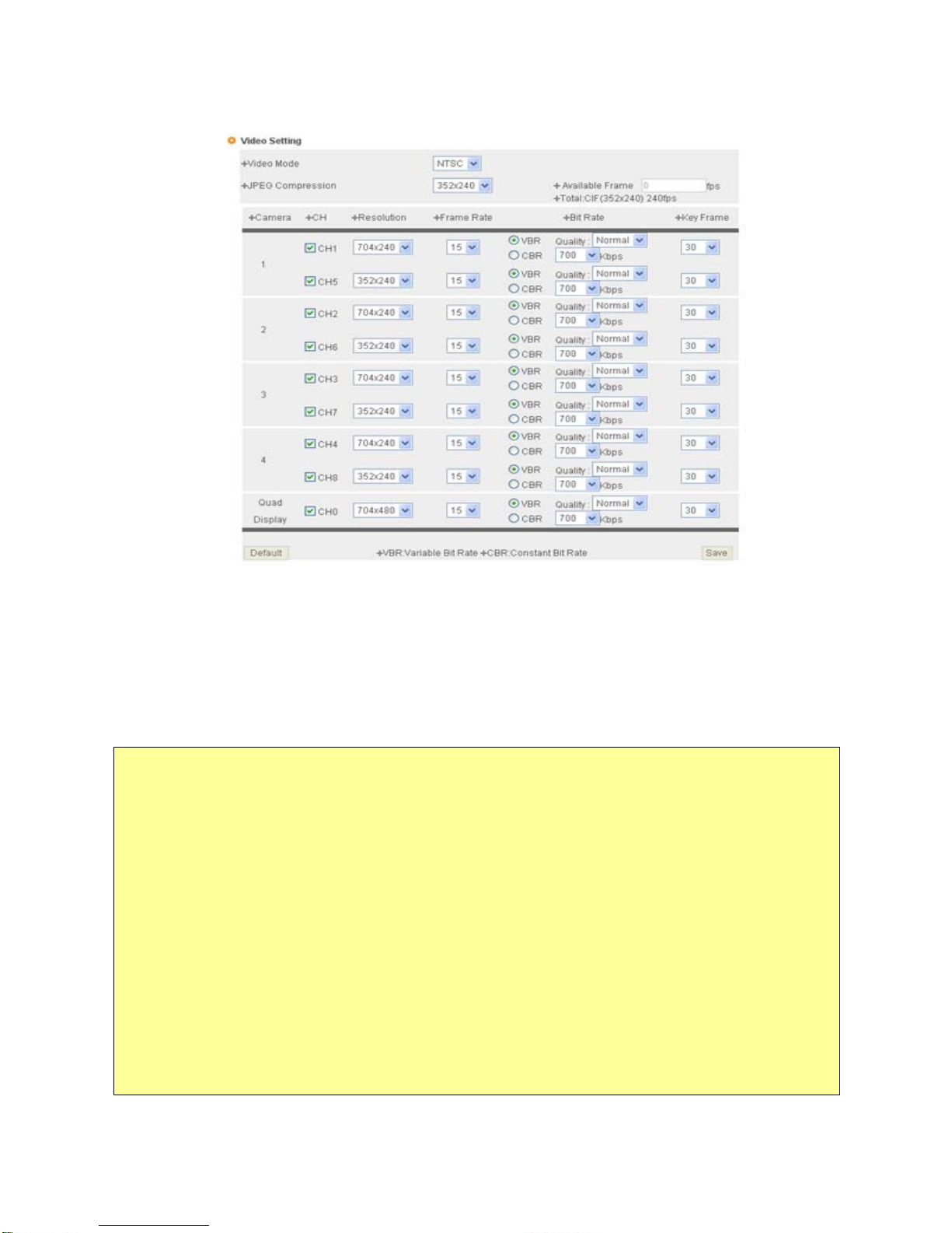
Select and tick on the Channel to use, input Video format (NTSC or PAL), Resolution, Bit rate, Frame rate and
Key frame.
Page 35
35
Pic. 4―15 Video Setting
① Video Mode: Select video mode according to the type of the camera you connect to S-160.
② JPEG Compression: This option is used when you view images on cellular or PDA. Two kinds of
compression image sizes are available; 352X240 / 176 X 120
※ Dual-Streaming
CryptoTelecom’s proprietary encoder chip, CT6009 is embedded into S-160. CT6009 enables users to configure
two different video setting from one analog video source.
Dual-streaming function can be used in two ways as follows.
1) Bandwidth: Clients have various network bandwidths to access S-152. If clients use broadband, they never
have problem with achieving live images from S-152. But if they don’t, live images canno t be viewed smoothly.
For smooth video images for clients using not only broadband but also narrowband, S-152 can be config ured as
two different video setting.
For example, you can set ‘dual-streaming’ as follows;
For broadband users: 704X480, 30fps, VBR, High Quality
For narrowband users: 352X240, 7fps, CBR, 100kbps
2) Preference between image quality and video smoothness: Video setting will affect the performance of S-152,
depending on the usage and the available bandwidth.
z High resolution generates larger files
Page 36
36
z Lower compression improves image quality, but generates larger files.
z Black & White uses less bandwidth than color.
z Rotating the image 90 or 270 degrees will lower the maximum frame rate.
Under certain circumstance with fixed bandwidth, some clients prefer image quality to video smoothness and
others, the reverse. Dual-streaming can be set as follows;
For better image quality: 704X480, 7fps, VBR, High Quality
For better video smoothness: 320X240, 30fps, CBR, 200kbps
③ Channel Video Setting
¾ Video Setting: S-160 encodes one video source into two different video channels. That is, user can set
up two different encoding configurations such as image size and bit rate on one video source from one
analog camera.
※ Maximum Frame Rate: 240fps at CIF(352X240) or 60fps at 4CIF(704X480)
¾ Available Frame Rate: This shows the remains of possible frame rate that user can set up. If this shows
“0”, user cannot set up additional video channel setting.
¾ CH (Channel): “CH” shows the number of camera displayed on the viewer when user access to S-160
and view the live images.
☞ NO. 1 camera can be accessed through CH 1 or CH 5
☞ NO. 2 camera can be accessed through CH 2 or CH 6
☞ NO. 3 camera can be accessed through CH 3 or CH 7
☞ NO. 4 camera can be accessed through CH 4 or CH 8
¾ Resolution: Configurable as 704x480, 704x240, 352x480 or 352x240
¾ Frame Rate: Configurable as 1 ~ 30 fps
¾ VBR (Variable Bit Rate): The VBR mode will maintain a high, if so defined, image quality regardless of
motion or no motion in the image scene. This is often desirable in security and surveillance applications
when there is a need for high quality, especially if there is motion in the picture. Since the bit-rate in
VBR may vary, even though an average target bit-rate is defined, the network infrastructure (available
bandwidth) for such a system needs to have this capacity.
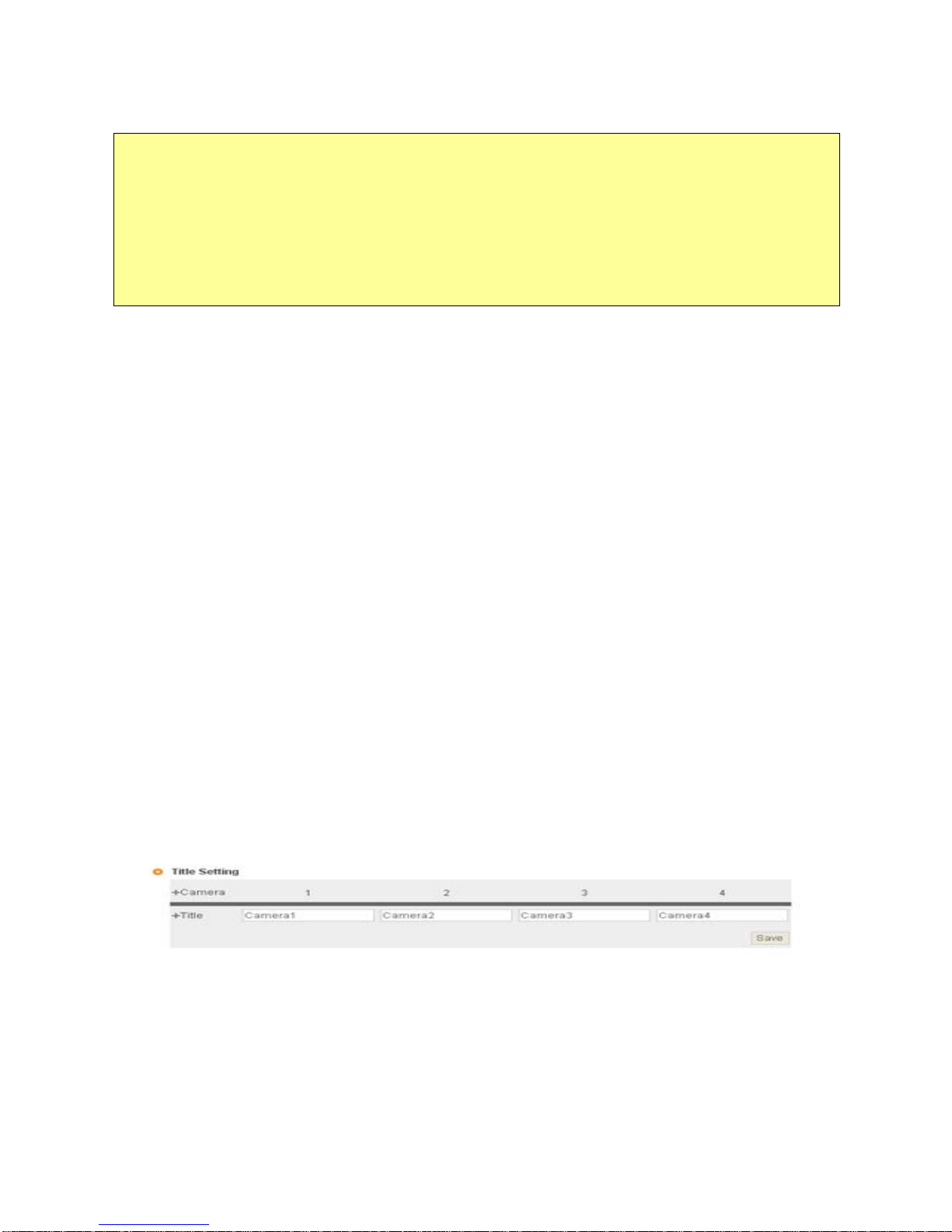
Pic. 4―16 Title Setting
¾ Users can freely set up the name of each camera channel and the name is shown on web viewer
display.
Page 37
37
4.3.2 Audio Setting
Pic. 4―17 Audio Setting
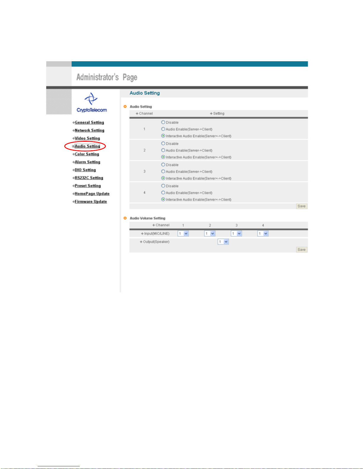
For one way audio communication, check ‘Audio Enable (Server -> Client)’ of [Pic.4-17], And for two way
audio communication, check ‘Interactive Audio Enable (Server -> Client)’. In case Audio is not used , check
‘Disable’. Then click ‘Save’ to save Set value.
For adjustment of audio volume, select in ‘Audio Volume Setting’ and s av e in [Pic .4-1 7] .
Page 38
38
4.4 Color Setting
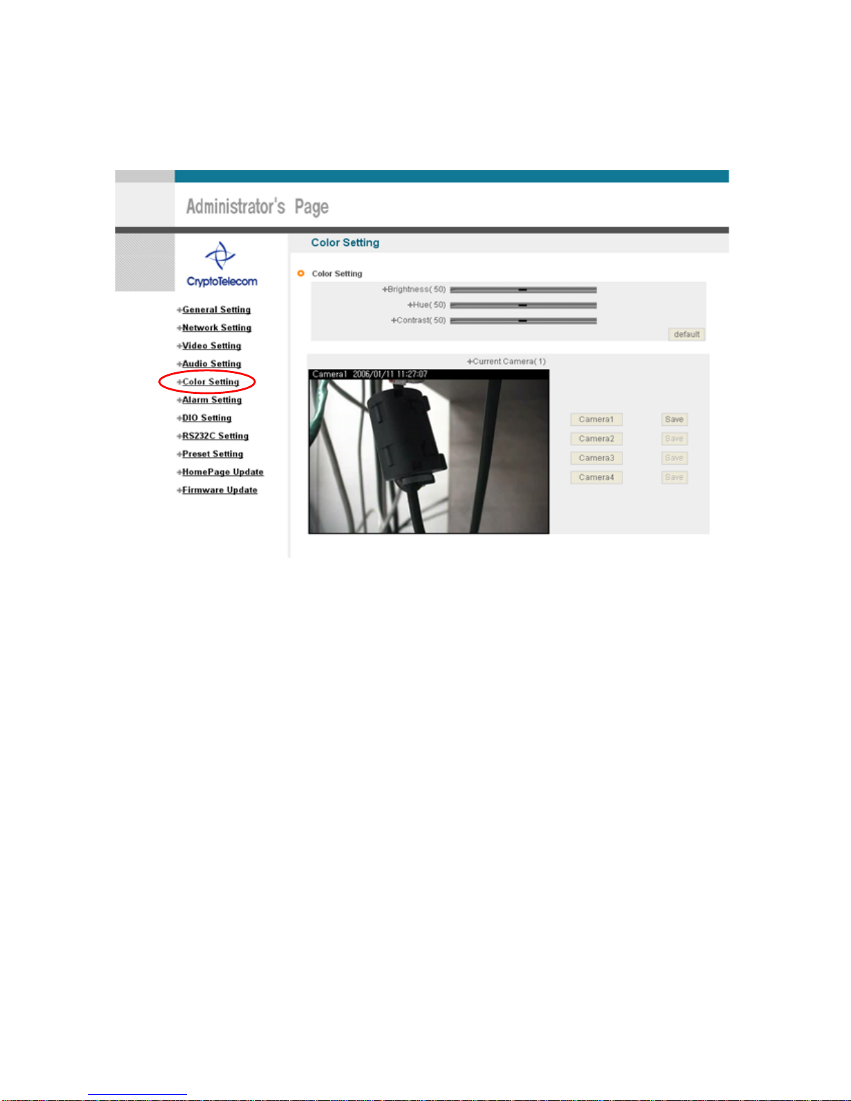
This is to adjust color of channel.
Pic. 4―18 Display Color Setting
Upon adjustment of color on [Pic.4-18], then click ‘Save’ to save the setting value. In case to return to default
value, click ‘Default’. Even in this case, it is required to click ‘Save’ Button for saving the setting value.
Page 39
39
4.5 Alarm Setting
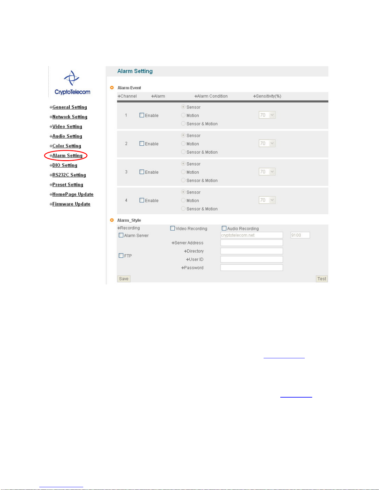
Pic. 4―19 Alarm Setting
4.5.1 Alarm Event Setting
To get Alarm Service on S-160 go to ‘Administrator's Page’Æ’Alarm Setting’ and tick ‘Enable’ in ‘Alarm’.
Designate condition to drive Event in ‘Alarm Condition’, s uc h as Sens or E ven t, Moti on detec tio n Ev ent or
Sensor + Motion detection Event, If Sensor Event is selected, do Sensor setting in ‘4.6 DIO Setting’
.
9 Sensitivity : To select the sensitivity of motion detection. The larger number represents higher
sensitivity to motion.
Upon Event situation after setting on ’Enable’ in ‘Alarm’ of ‘Alarm Event’, Event is to be transmitted to user’s
Viewer and inform detection of Event, with flickering on screen and alarm sound. (refer to 5. Basic Use
).
To use SMS Service and E-mail transmitting Event to Alarm Server, go ‘Alarm Style’-> ‘Alarm
Server’ and input Domain Name of Alarm Server (Default of ‘Alarm Server’ is cryptotelecom.net as ex-
Page 40

40
factory condition).
To send the recorded video to FTP Server upon alarm event, go ‘Alarm Style’-> ‘FTP’ and input FTP Server
Address, Directory, User IP and Password, FTP Directory (mandatory). Make user’s directory in FTP root of
User’s FTP Server to get recorded files to be transmitted. Click ‘Save’ Button to save setting value.
In case of setting to send Event to Alarm Server, register S-160 in PIMA Server to use Alarm Server (refer to
‘‘Use of PIMA Server
’ in ‘ 5. Basic Use)
4.5.2 Alarm Style
Click ‘Test’ of [Pic 4-19], S-160 will work as if Alarm has happened. In case ‘Alarm Style ->’Alarm Server’ is
selected, Event is to be notified to Alarm Server and is to recorded into the recorded file (10 seconds before
and 20 seconds after Event), and to be sent to Alarm Server.
In case user FTP Server is selected to use, the recorded file (10 seconds before and 20 seconds after Event)
is to be saved in FTP Server. It may take some time for Alarm Message to get to user’s Mobile Phone or by
E-mail, in some cases. If S-160 has been registered in PIMA Server, it is available to check the details of
Event and also change the Alarm Message of E-mail and Mobile Phone to be sent upon Event, in Alarm
Server Homepage (.cryptotelecom.net). Refer to ‘Use of PIMA Server
’ in ‘ 5. Basic Use’ for details.
Page 41
41
4.6 DIO Setting
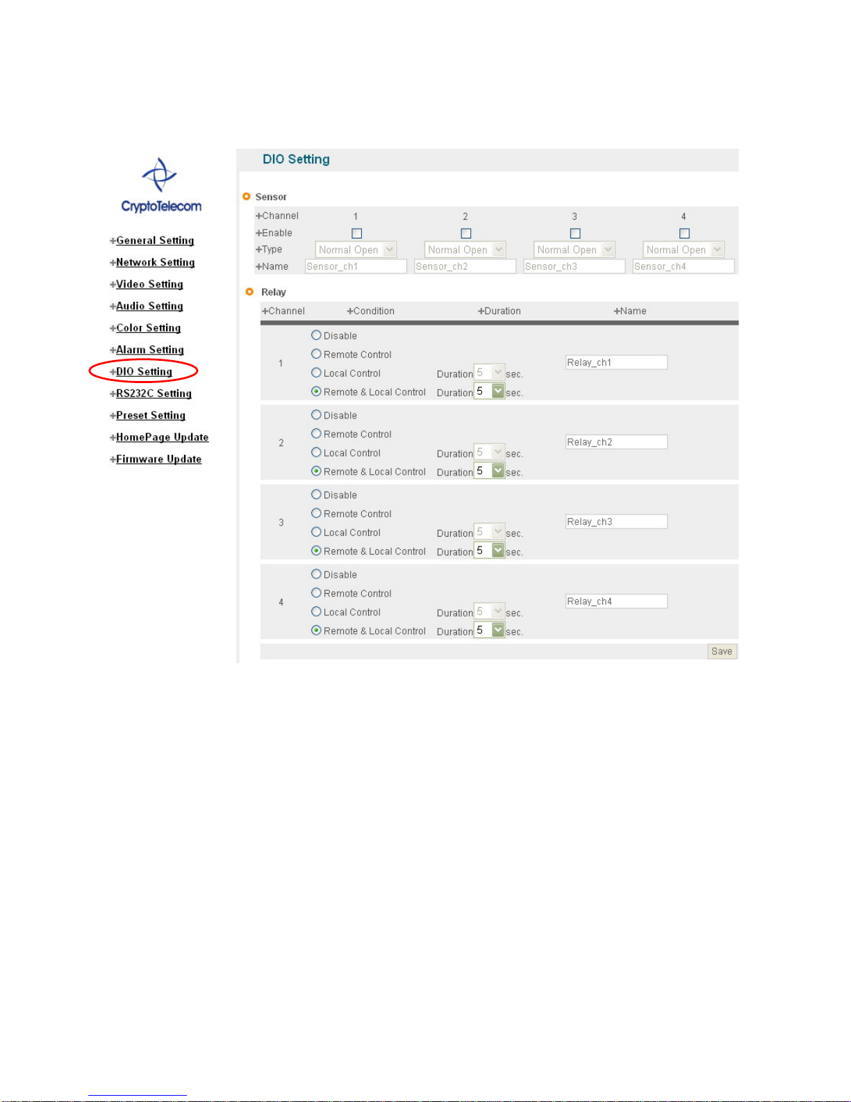
Pic. 4―20 DIO Setting
Tick on sensor to use and select type of sensor to use.
9 Sensor Type : designate type of sensor, NC, NO.
Designate name of sensor to use.
4 conditions are selectable for Relay. Relay name is to be input.
9 Disable : not to use Relay
9 Remote Control : to control Relay through Internet using Viewer
9 Local Control : Relay is on during ‘Duration’ time upon Event on Sensor, and then is to be off.
9 Remote & Local Control : Control Relay through Internet using Viewer. To be ON during ‘Duration’
time upon event on Sensor, then to be OFF. It’s available to designate name on Relay to use.
Page 42
42
4.7 RS232C Setting
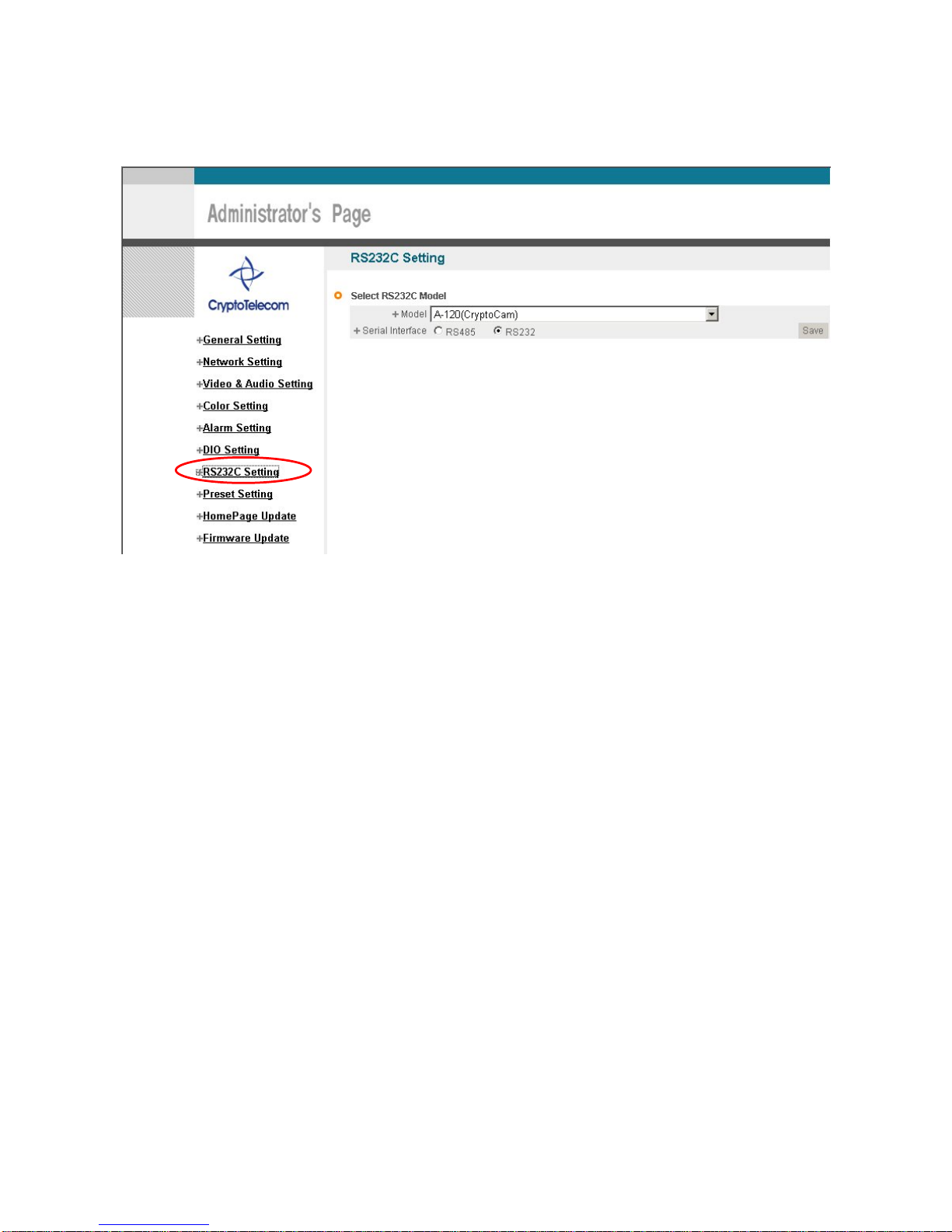
Pic. 4―21 RS232C Setting
It is available to select P/T/Z module supported or P/T/Z Integrated Camera. Models of Camera supported by
S-160 are:
A-120 (CryptoCam / RS232),
Canon VC-C4R (RS232),
Wonwoo PT-101 (RS485),
Technovision SECUMERA_PRO (RS485),
LG Electronics LPT-A100L(RS485),
ShinTech SD-290(RS485),,
Dongyang Unitec DRX-500,DRX-502A,DOH-240 (RS485), DSC-230Si,DSC-270Si,DOH-240Si (RS485),
Hitron Fastrax2 (RS485).
IZIrobotics A.I Robot TOBO[T-010](RS485)
CNB Technology AN201L(RS485)
Sunkwang SK-D106(RS485)
TYCO/CTNCOM HD-0670(RS485)
SAMSUNG SRX-100B/SPT-5IO/SCC-C4201/SCC-641/SCC-931T (RS485)
PELCO PELCO-D 2400, PELCO-D 9600 (RS485)
Sony EVI-D100/D70
Sysmania ORX-1000
Page 43

43
New Models will be added to supporting module in the near future continuously by Firmware Upgrade.
RS232 and RS485 is available for Serial Control. It is available to select the control method. RS 232C BYPASS
function is to send user’s data through R-232 of S-160. When using this function, Pan/Tilt/Zoom can not be
used.
RS232C Bypass Control
9 To use RS232C Bypass, set as ‘RS232C BYPASS’.
9 User’s data is to be sent thought RS232 of S-160.
Example) * Transmit Data : 0x6F,0x70,0x,65,0x6E
BYB9600=1Aopen
* Transmit Data : 0x6F,0x70,0x,65,0x6E
BYB9600=1B6F70656E
Explanation: ->‘BYB’ : Fixed (not changeable)
->’9600’ is baud rate(2400,19200,38400….)
->’=’ : fixed (not changeable)
->’1’ : type(1: 8bits No parity 1 stop bit
2: 7bits Even parity 1 stop bit
3: 7bits Odd parity 1 stop bit)
->’B’ : Type of date to transmit(A:ASCII, B:Binary)
->’ 6F70656E’ : Data to transmit
Page 44
44
4.8 Preset Setting
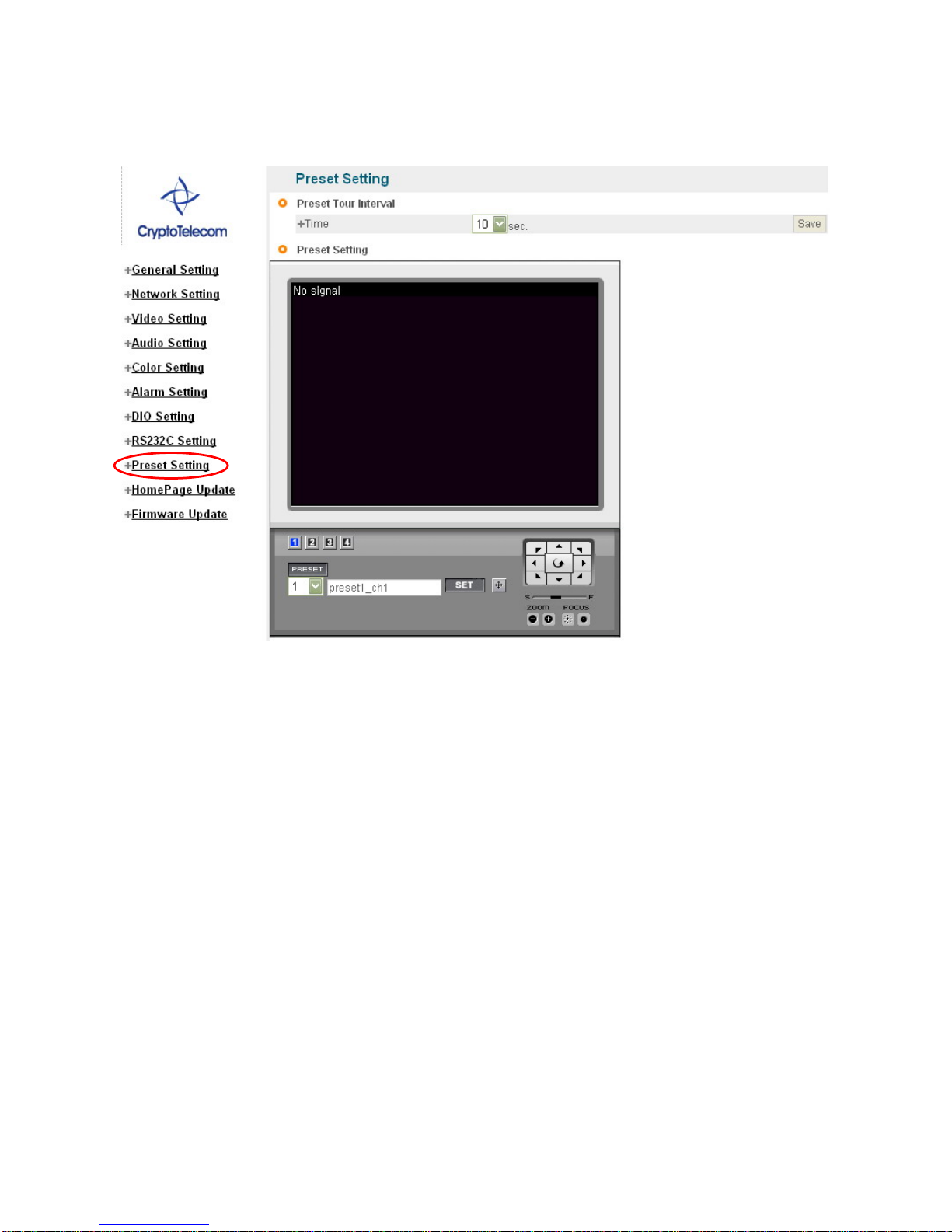
Pic. 4―22 Preset Setting
It is available to pre-set Pan/Tilt/Zoom Cameras. Preset Setting is available up to 20, but may be less than 20 for
some model of Camera.
9 (1) : Select Channel ; to select the channel to preset.
9 (2): Preset No. : to select the Preset Number to set up.
9 (3): Preset Name : to input Name of Preset to set up, Preset Name is be 30 character, without space
and special characters.
9 (4): Preset SET ; ‘SET’ button is to set the current coordinate as preset location with name recorded by
user. In three seconds after pushing ‘SET’ button, the Preset coordinate is to be set. Do not move
Camera during the time (about three seconds).
9 (5): Preset Move : to move to the selected preset number.
9 (6): Adjustment of Pan/Tilt/Zoom/Speed/Focus : to move to the location to preset by adjusting
Pan/Tilt/Zoom/Focus.
Time interval for preset tour mode can be set up, from 1 to 40 seconds.
①
②
③④
⑤
Page 45
45
4.9 Homepage Update
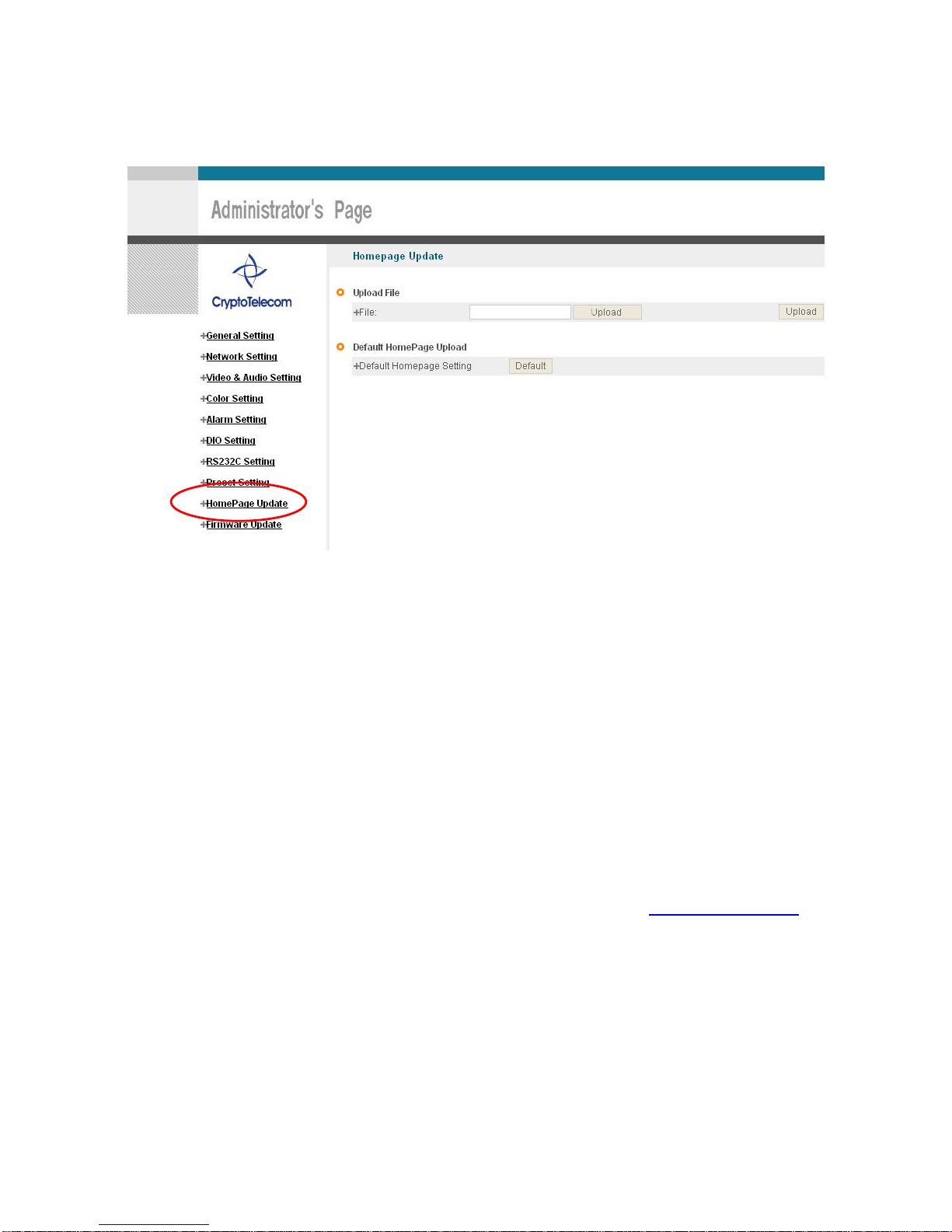
Pic. 4―23 Homepage Update
Homepage Update function is for user to upload the main page of S-160 onto user’s Homepage. User’s
Homepage is composed of 3 files as like index.html, top.htm, main.htm. The file for user to use is main.htm.
After making Web Page (main.htm) and save it as file name of main.htm, upload by the function of ‘Homepage
Update’, then manin.htm page is to be the 1st main page of S-160.
(Image file is not uploaded in S-160.) User Homepage cannot exceed 300Kbyte.
If user wants to re-make user’s homepage into Homepage provided complimentarily, click ‘Default Home Page
Upload’.
4. 10 Firmware Update
4.10.1 Remote Upgrade
In case firmware is upgraded in the near future, Crypto telecom’s Upgrade Server (Http://cryptotelecom.net
) will
automatically upgrade Firmware of S-160. Upgrade is only supported via Internet. Information on the latest
version of S-160 will be posted in Data Room of Crypto telecom’s Homepage. Remote Upgrade
Page 46

46
Pic. 4―24 Firmware Update
Address of ‘Update Server Address’ in [Pic.4-24] is basically set as ‘cryptotelecom.net’.
Check ‘Current Software Version’ in ‘Current Version’ of [Pic.4-24] and go ahead with update if current version is
lower than the latest version. Upon clicking ‘Update’ button in [Pic.4-24] ‘Remote Update’, [Pic.4-25] will appear.
Pic. 4―25 Firmware Update
S-160 will be automatically upgraded upon clicking ‘Download’ button of [Pic.4-25] after connecting to Upgrade
Server and checking ve rsion.
Pic. 4―26 Firmware Download
‘Downloading’ message will be shown until completion of Update as [Pic.4-26] (it may take time according to
Network situation). Upon completion of upgrade, there appears message showing upgrade result.
Page 47
47
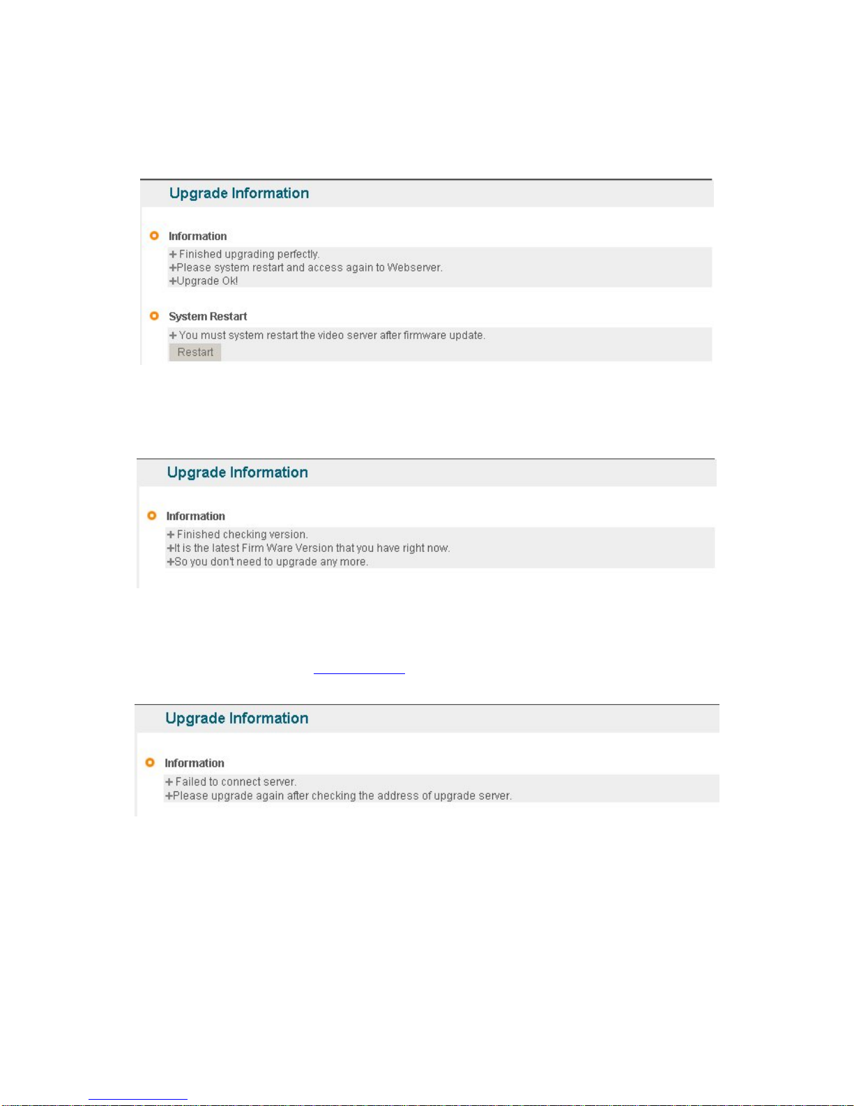
[Pic. 4-27] is the message showing that upgrade has been correctly done. Click ‘Restart’ in ‘System Restart’
to restart System of S-160.
Pic. 4―27 Completion of Upgrade
If [Pic. 4-28] is displayed as below, it means that S-160 has been upgraded to the latest Version, there is no
need to update any more.
Pic. 4―28 Check of Upgrade Version
If user found [Pic. 4-29], there is an error in connection to Upgrade Server, re-check Internet Connection or
re-check DNS Server Address in ‘3. Basic Setting
’ and try to upgrade again. If user keep finding [Pic.4-29] or
cannot upgrade, contact head office of CryptoTelecom Co., Ltd. or local agent.
Pic. 4―29 Upgrade Server Connection Error
4.10.2 System Re-booting
This is the function to re-boot Inner Software of S-160. Click ‘Restart’ on [4-41] ‘System
Restart’ to reboot all inner program of S-160.
Page 48

48
5. Basic Use
Page 49
49
5. Basic Use
5.1 Use of Web Viewer
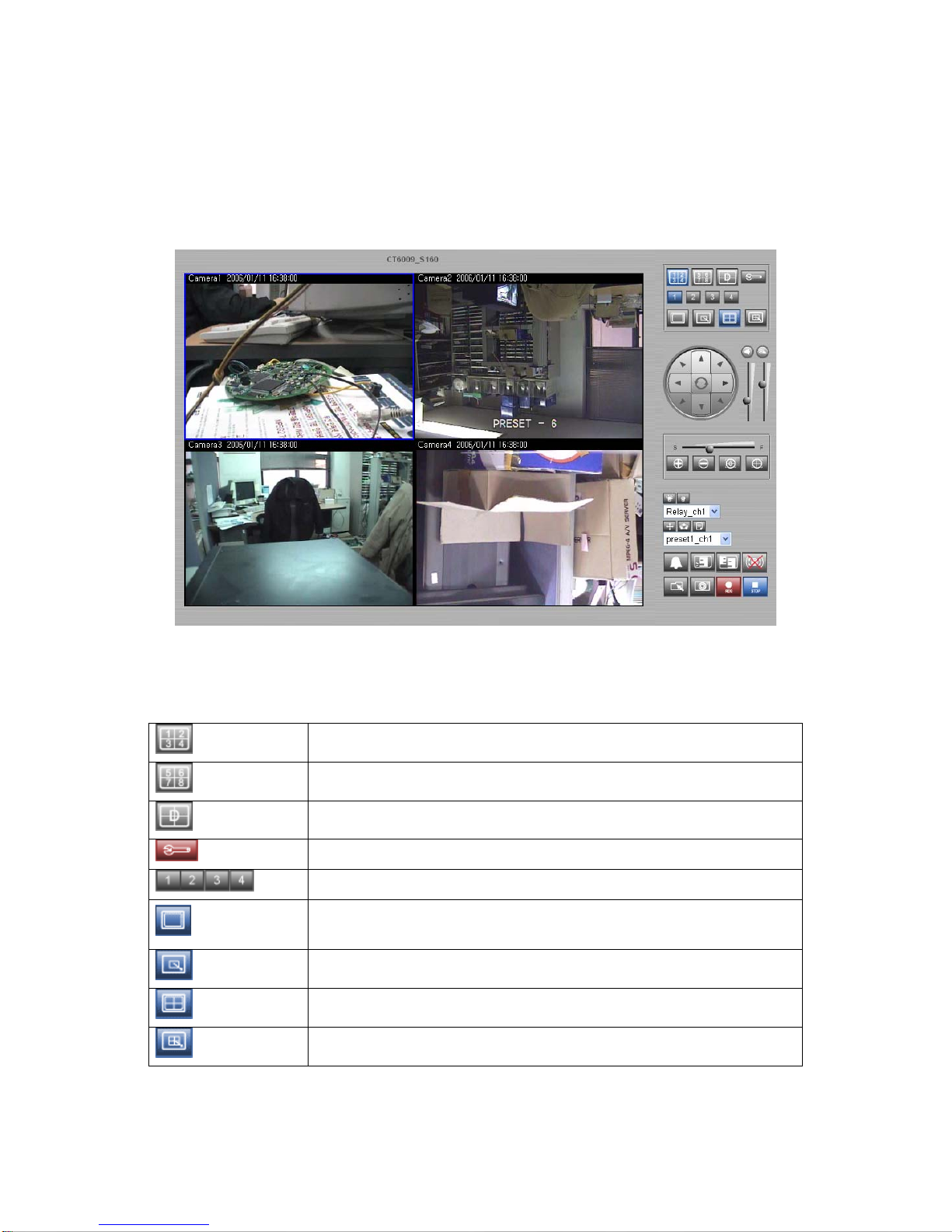
Pic. 5―1 Web Viewer
Table. 5-1 Definition of Web Viewer Button Function
Connect D1 (1 of Dual streaming)
Connect D2 (2 of Dual streaming)
Connect quad display channel
Link to ‘Administrator’s Page’
Connect each single channel
Display Screen 100%. Double-clicking mouse on enlarged screen has the
same function.
Enlarge Video of a channel to full screen
Display 4 channels simultaneously
Enlarge 4-channel-display to full screen
Page 50
50
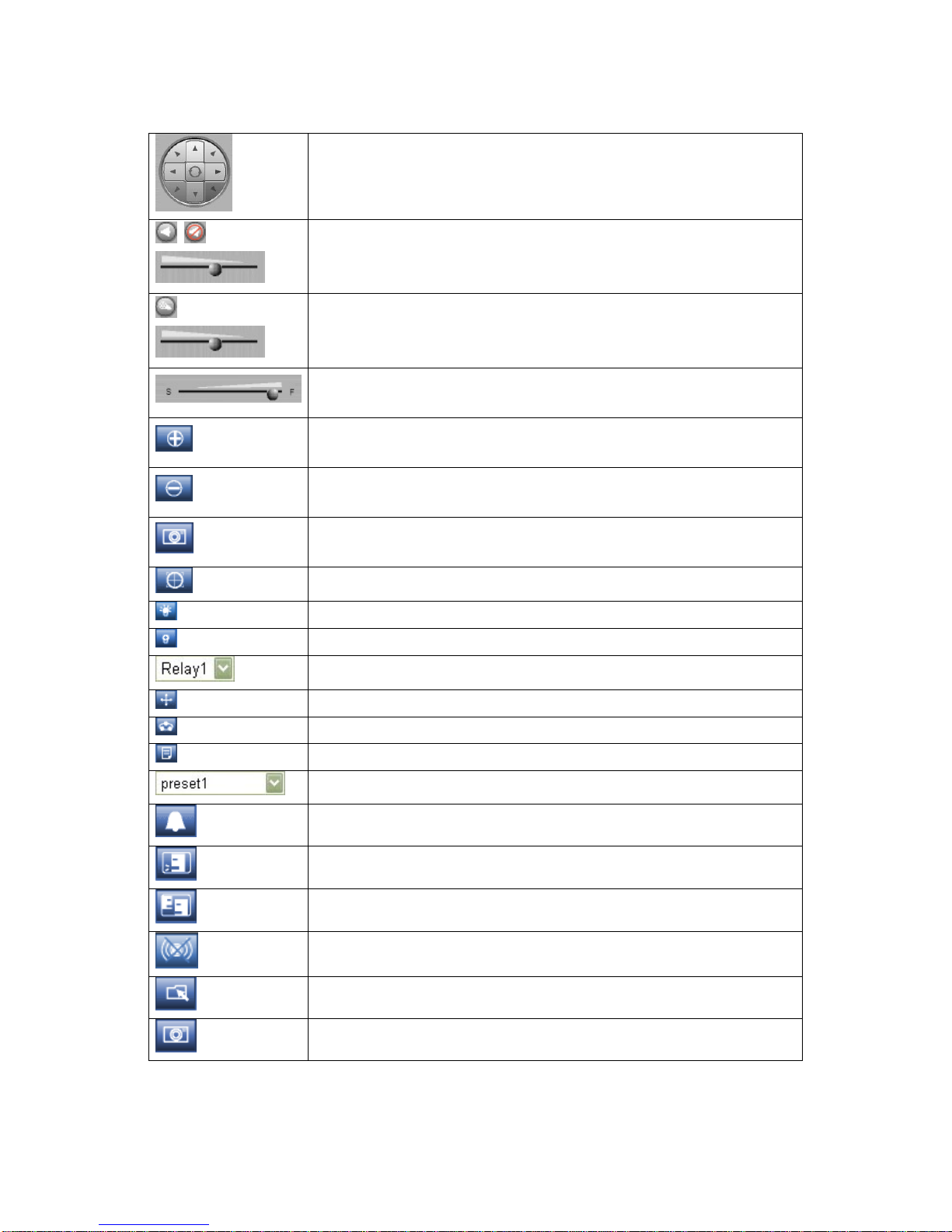
While pressing Mouse on the direction arrows for Pan/tilt, the camera moves
in that direction as long as the mouse is depressed. The center arro w key
will turn the unitized PTZ camer as off (Canon and Sony PTZ Cameras).
Speaker on / off
Speaker volume control
Microphone (always activated)
Microphone volume control
Control Speed of pan/tilt - ‘S’ makes speed of Pan/tilt slow. ‘F’ makes
speed of pan/tilt fast. (Some camera models will not respond)
Zoom In: Pressing this button makes the lens Zoom-in. Un-pressing stops
the function.
Zoom Out: Pressing this button makes the lens Zoom-out. Un-pressing
stops the function.
Focus Far: Allows fine focus of Camera manually (far).
Focus Near: Allows fine focus of Camera manually (near).
Relay On.
Relay Off.
Select preset to control.
Move to the selected Preset
Preset Tour: Move to preset location in regular sequence from No. 1 to 20.
Bring camera menu on the screen. (Some camera models will not respond)
Select preset to control.
Go off beep sound to call.
One-way audio communication.
Two-way audio communication.
Beep off.
Designate the folder to record and capture live images.
Capture Image on the screen.
Page 51
51
Record live images.
Stop Recoording.
Flickering on Screen
and Alarm Sound
Upon detection of an Event on StreamVIEW, there will be a flickering on
Screen and alarm will start beeping. To stop the sound, double-click on the
flickering screen.
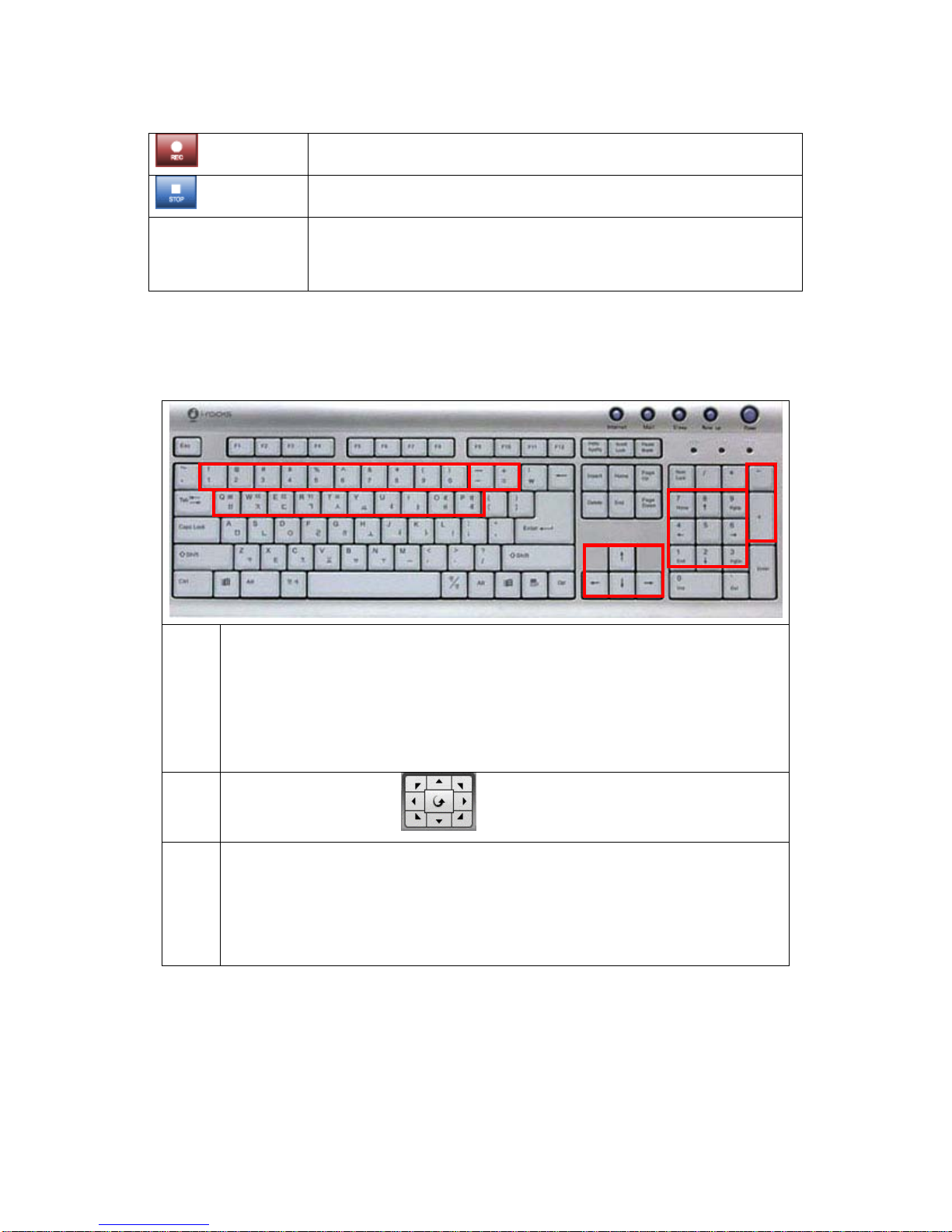
Table 5-2 Definition of Web Viewer Key Board
①
9 Number Key’
9 Preset Move Function,
9 The Number represents the Preset Number
9 20 Preset is controlled by Key Board
9 Key Board 1 ~ 0 : Preset 1 ~ Preset 10
9 Key Board q ~ p : Preset 11 ~ Preset 20
③④
9 Same function as
②⑤
9 Zoom-in, Zoom-out Function
9 ‘+’ is Zoom In, Pressing the key makes doing the function. Un-pressing stops
the function
9 ‘-‘ is Zoom Out, Pressing the key makes doing the function. Un-pressing stops
the function.
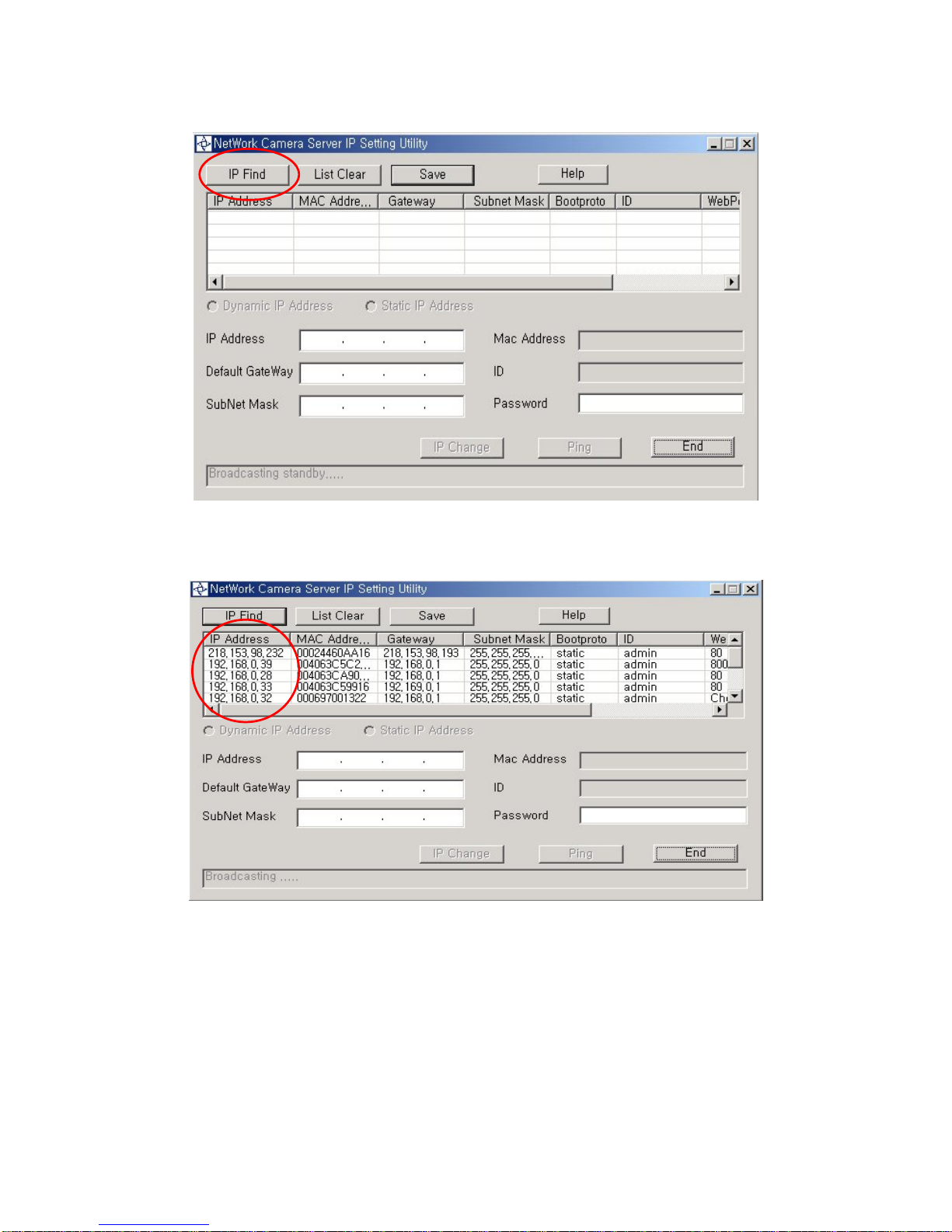
5.2 Use of IP Setting Utility
Upon running IP Setting Utility, the following program is to be displayed.
①
②
③
④
⑤
Page 52
52
Pic. 5―2 IP Find
Click ‘IP Find’ Button to find IP of S-160 on local Network.
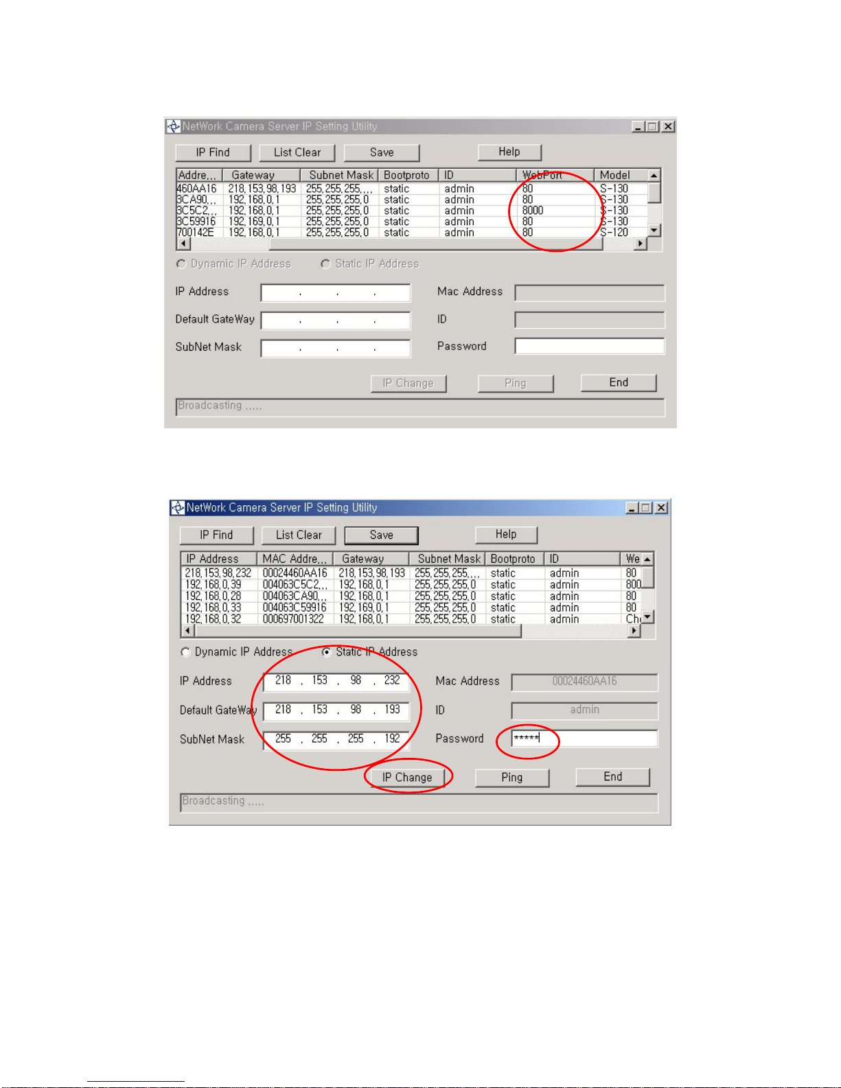
Pic. 5―3 Display IP
The following window shows list of IP alon g with Web Server Port Number and Model Name of S-
160. Click ‘IP Find’ Button to find IP of S-160 on local Network.
Page 53
53
Pic. 5―4 IP Check
After finding IP, double-click IP of S-160 to go to the editable Mode as follows.
Pic. 5―5 IP Setting
Input new IP Address, Default Gateway, Subnet Mask, and then input Password of S-160 Administrator and
click ‘IP Change’, to set up new IP of S-160. Upon completion of setting, find new IP and click ‘Ping’ to check
whether setting is done normally, and close the program by clicking ‘End’ button.
Page 54
54
5.3 Use of PIMA Server
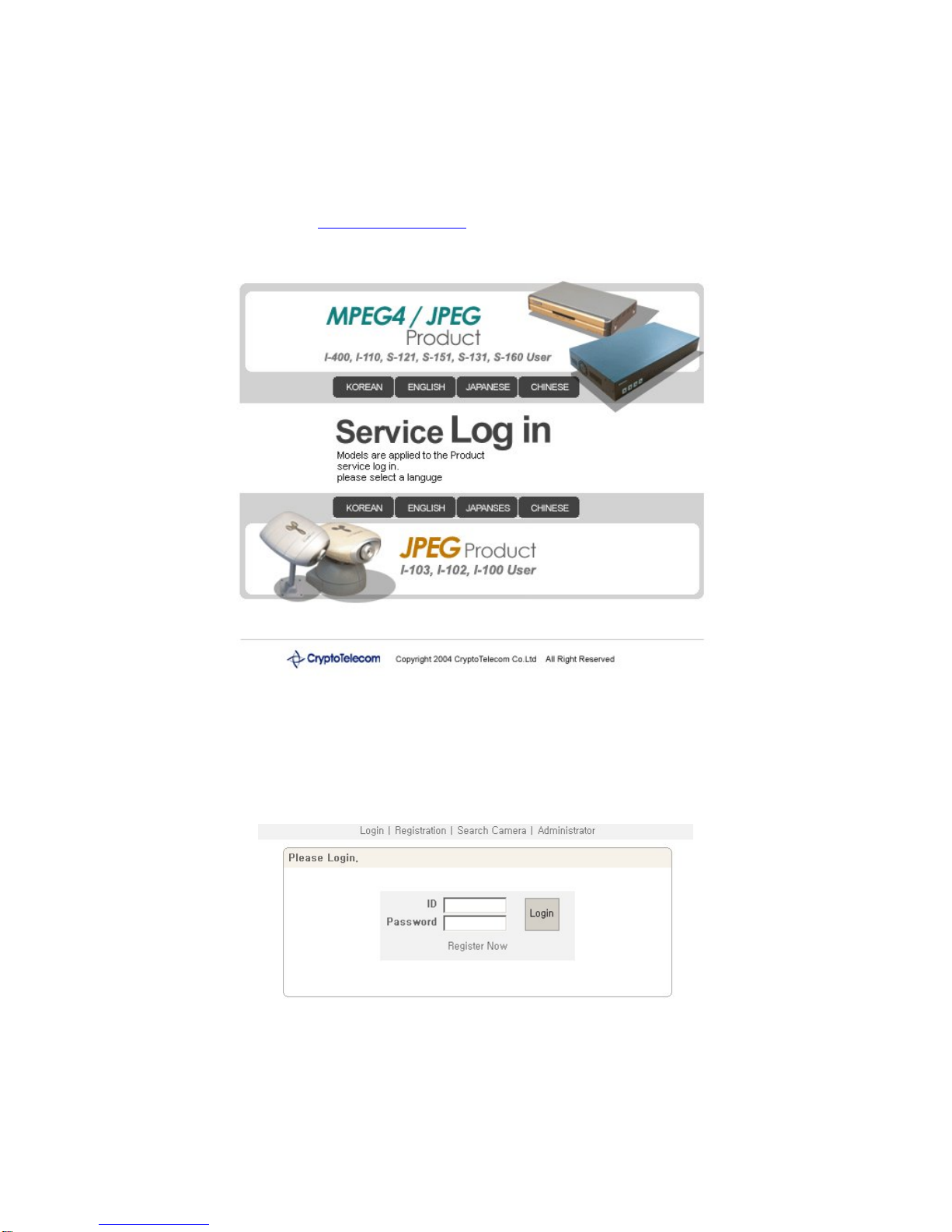
Run Web Browser and input http://cryptotelecom.net in URL and click ‘Enter’, then [Pic.5-6] will appear as
follows.
Pic. 5―6 PIMA Server
Click the language user want to use.
5.3.1 User Registration
Pic. 5―7 User Login
Page 55
55
Click ‘Register Now’ in [Pic.5-7].
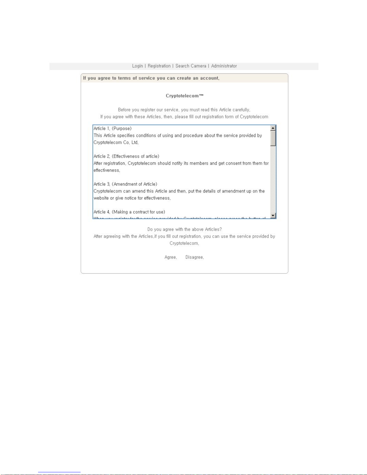
Pic. 5―8 Agreement
Read the Agreement carefully and click ‘Agree’ in case to agree, and go to the next page.
Page 56
56
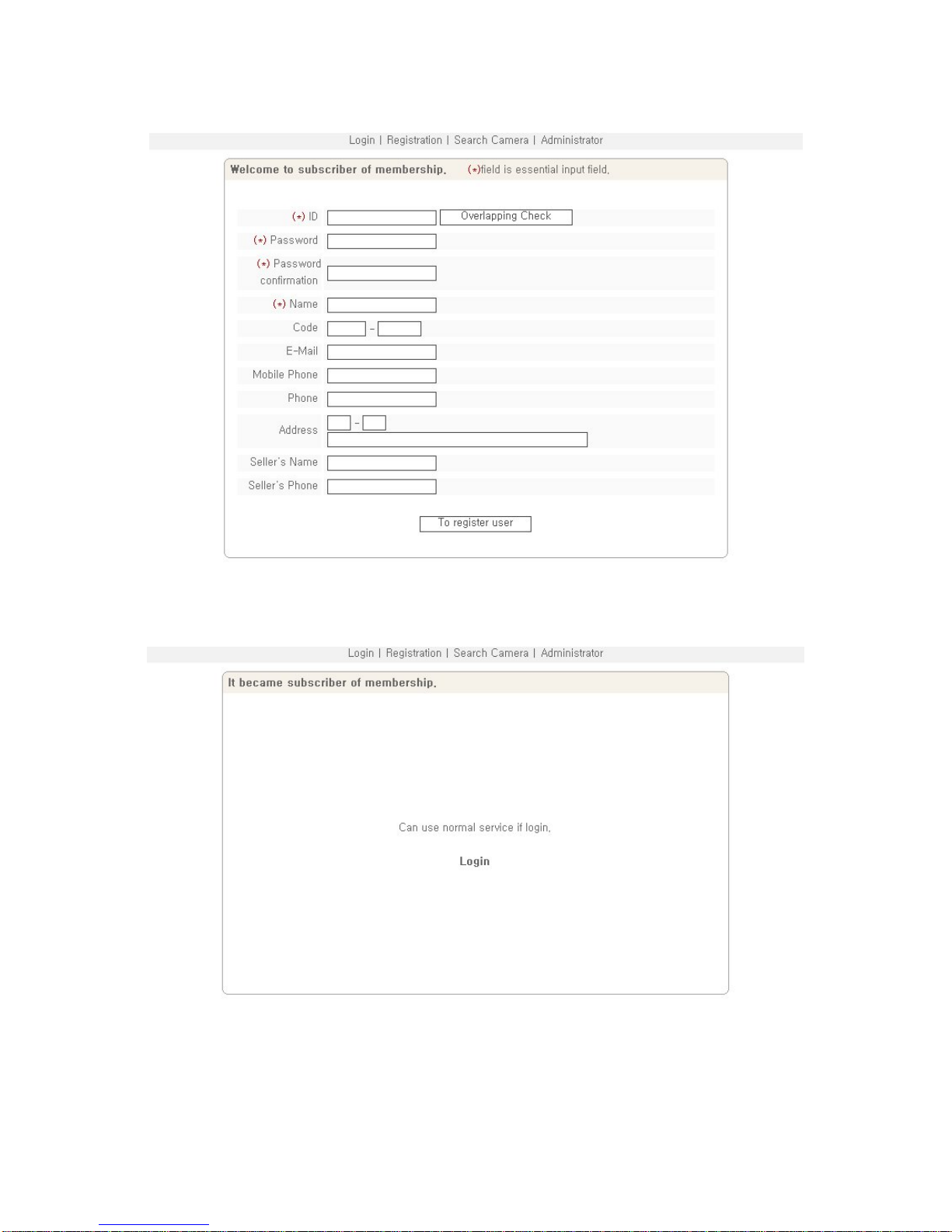
Pic. 5―9 User Registration
The part marked with (*) is mandatory. User ID is to be double-checked. Then click ‘Log In’.
Pic. 5―10 User Registered
If [Pic.5-10] appears, User Registration has successfully completed. Click ‘Log-in’ and input User ID and
Page 57
57
password on [Pic.5-7] to connect to PIMA Server.
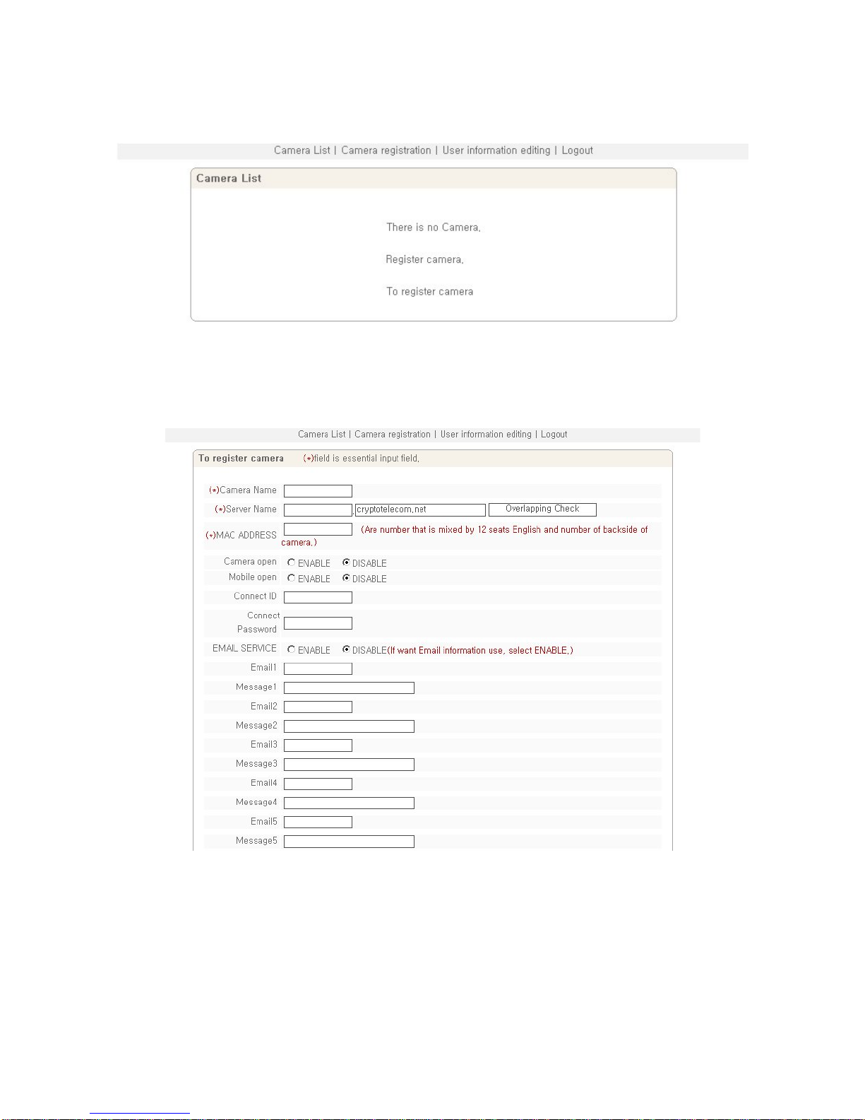
Pic. 5―11 PIMA Log-in Succeeded
5.3.2 Camera Registration
Click ‘To register camera’ in [Pic.5-11] to go to Camera Registration Page.
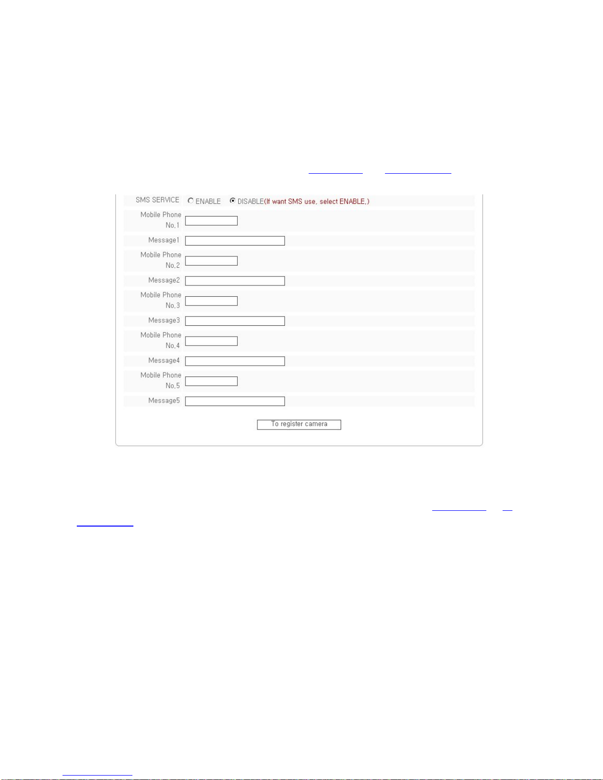
Pic. 5―12 Camera Registration
Input name of S-160 in ① of [Pic.5-12], which will be applied only in PIMA Server.
At ②, Server Name is to input Domain Name to connect to S-160. It is recommended to give the name easy to
understand and remember as a Domain Name because it is available to connect to S-160 by Domain Name in
case not knowing IP address of S-160. Domain Name should not be duplicated. Register it after checking
Page 58
58
whether it is duplicated or n ot.
③ is to check whether the Camera is to be open or not. ④ is for the function to connect to S-160 easily by
User’s ID and Password registered in S-160, to monitor or control Video of S-160 on Mobile Phone. (Mobile
Phone Users should tick “Enable” and input connection ID and Password.)
‘EMAIL SERVICE’ is the function to send the set message to E-mail address set by user upon alarm on S-160 in
case user set the use of alarm server as Enable. (refer to ‘Alarm Setting
’ in ‘4. Expert Setting’). It is available to
input up to 5 Mail address and input up to 5 messages upon checking on ‘ENABLE’.
Pic. 5―13 Camera Registration
‘SMS SERVICE’ is the function to send the set message (SMS) from PIMA Server to Mobile Phone number set
by user upon alarm on S-160, in case setting to use Alarm Server as ‘ENABLE’. (refer to ‘Alarm Setting
’ of ‘4.
Expert Setting’). It’s available to input up to 5 Mobile Phone to get SMA Message and input up to 5 messages
upon checking on ‘ENABLE’.
Cautions : Input Mobile Phone Number without ‘-‘ or any space
Click ‘Camera Registration’ to save the registered information after input of all information.
5.3.3 List of Camera
Input the registered User ID and Password to connect to PIMA Server on [Pic.5-7].
Page 59
59
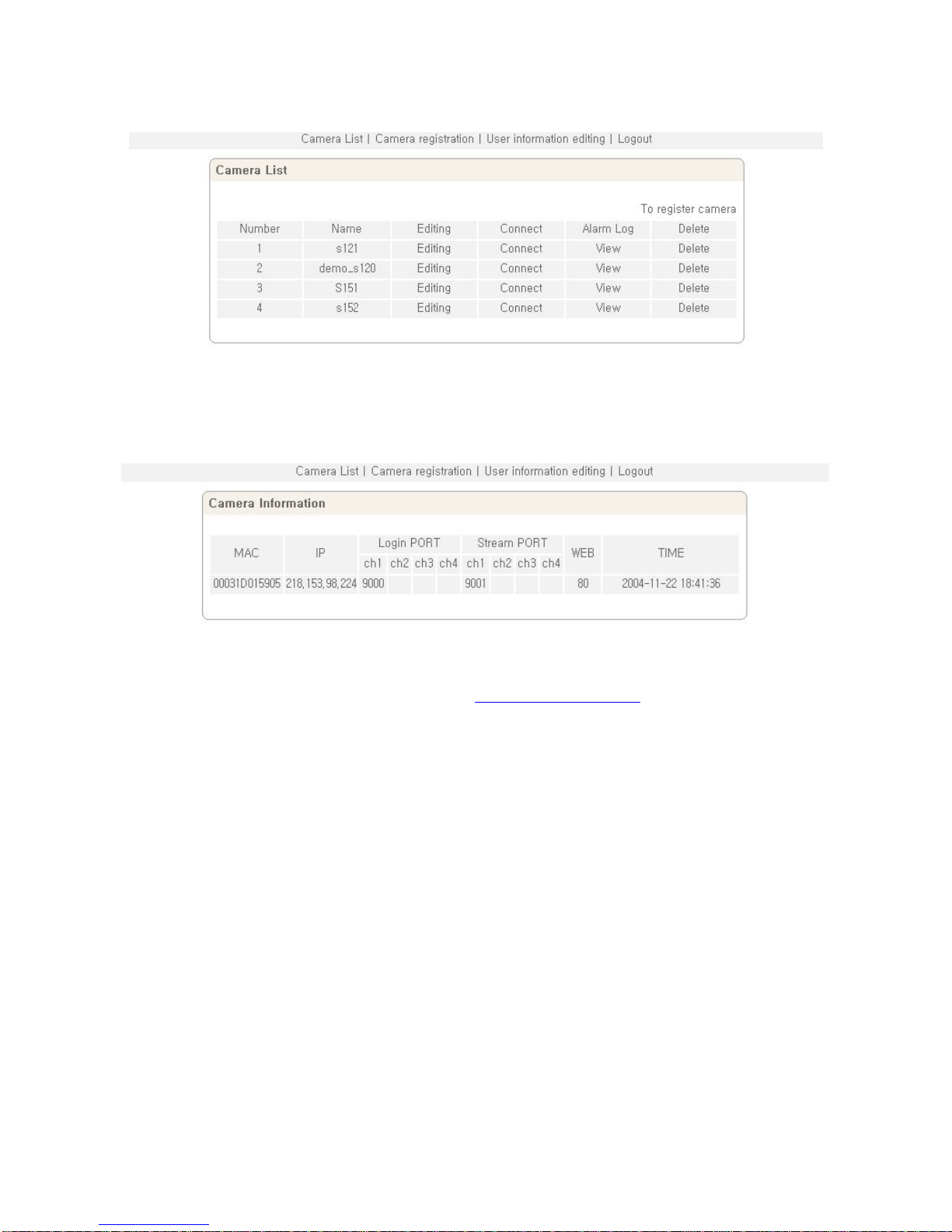
Pic. 5―14 Camera List
[Pic.5-14] shows the registered List of S-160. Upon clicking on ‘Camera Name’ registered in [Pic.5-14], [Pic.5-15]
will show the Camera Information. ‘Time’ is the latest time for S-160 to report to PIMA Server.
Pic. 5―15 Camera Information
On clicking ‘Camera Change’ on [Pic.5-14], the page of ‘5.3.2 Camera Registration
’ to change the information of
Camera registered, will appear. Change the information and click ‘Camera Change’ to save the new information.
‘MAC’ is not changeable. To change ‘Server Name’, double-check is required. Upon clicking ‘Camera Connect’
on [Pic.5-14], the main page of S-160 will appear.
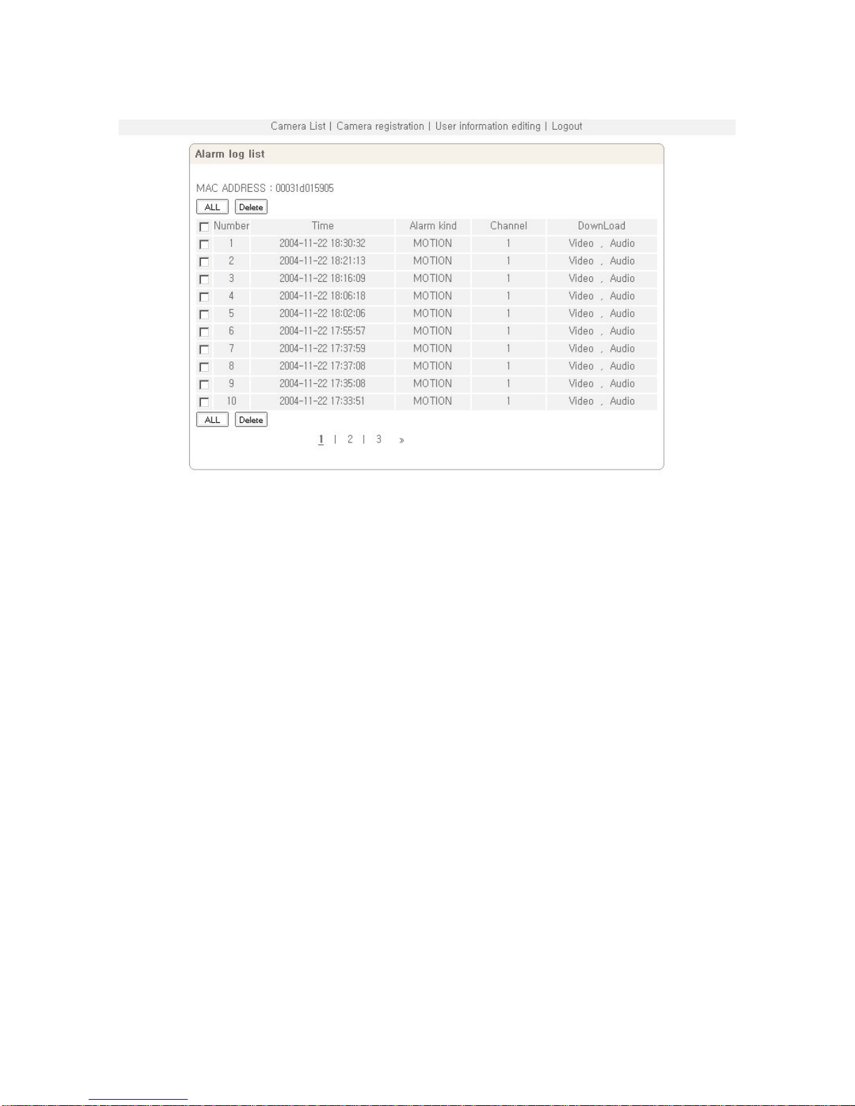
Upon clicking ‘Alarm Log List’ on [Pic.5-14], Event information transmitted to PIMA Server is to be displayed.
Event information is to be saved up to 20. In case of full saving up to 20, it overwrites the oldest one.
Page 60
60
Pic. 5―16 Alarm Log List
‘Alarm Log List’ shows the information of a channel, alarmed time, type of Alarm. It is available to delete the log
file. S-160 sends the recorded files, dividing into Video file and Audio files, to PIMA Server. In case there is no
recorded file, the message will show ‘No File’. In case the file has not sent to PIMA Server yet, the message
“Uploading” will be shown. If Video and Audio has been downloaded in “Download” of [Pic.5-16], user can
download and see the recorded file. “Camera Delete” of [Pic.5-14] is to delete the Camera from the list..
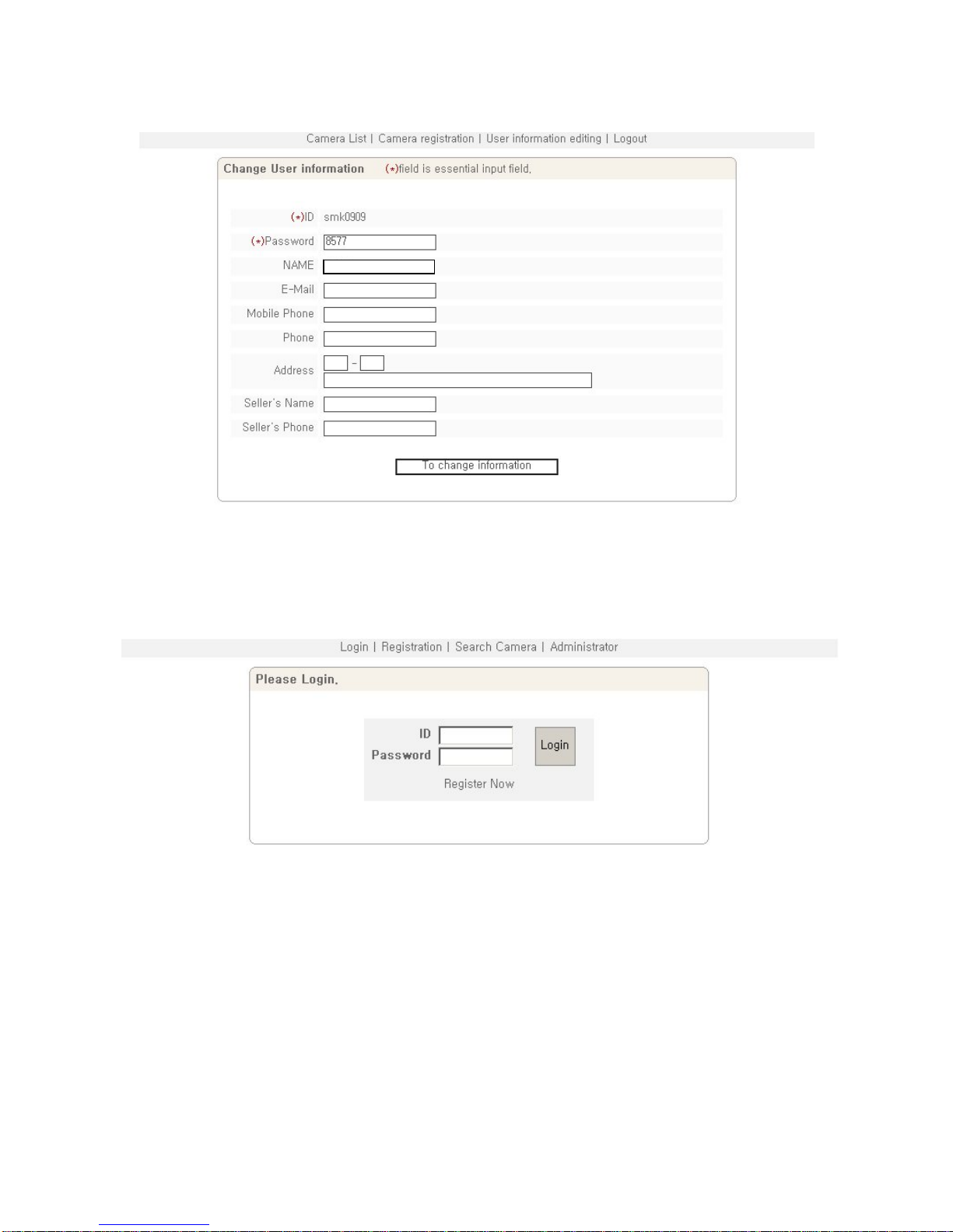
5.3.4 Change of User’s Information
On clicking ‘User’s Information editing’ in upper menu of [Pic.5-14], [Pic.5-17] will appear the page to change
user’s information.
Page 61
61
Pic. 5―17 Change User’s Information
Save User’s information by click ‘To Change Information’ after changing user’s information.
5.3.5 Search Camera
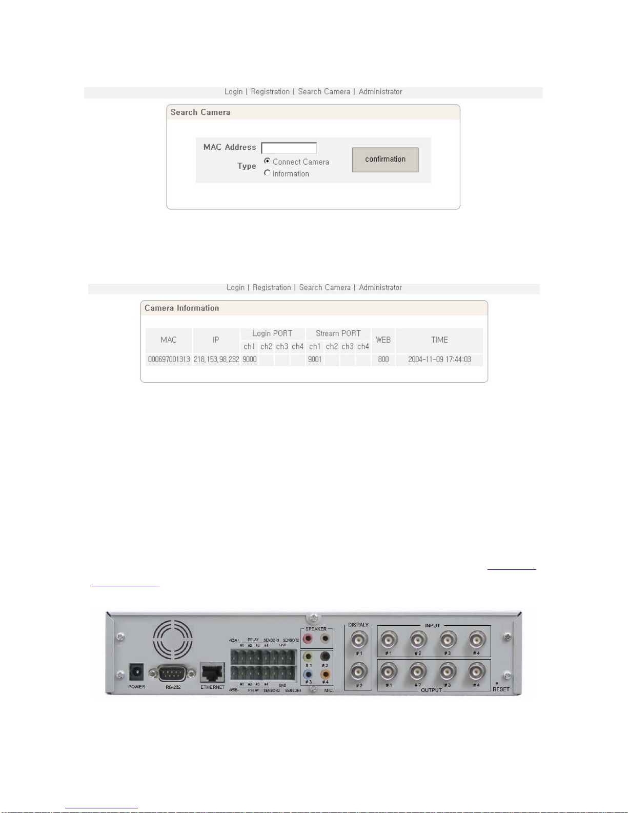
Pic. 5―18 Search Camera
‘Search Camera’ of [Pic.5-18] is the function to see information of S-160 or connect directly to S-160 without
user registration in PIMA Server. Upon clicking ‘Camera Search’ on [Pic.5-18], [Pic.5-19] to search Camera w ill
appear. ‘Type’ on [Pic.5-19] is to select ‘Camera Connect’ to connect directly to S-160 using MAC Address, and
then to input MAC Address of S-160 and click ‘Yes’, then S-160 will be directly connected.
Page 62
62
Pic. 5―19 Search Camera
If user want to see information of S-160 by MAC Address, select ‘Information’ and input MAC Address of S-160
to see information on, and click ‘confirmation’ .Then Information of S-160 w ill be shown as [Pic.5-20].
Pic. 5―20 See Information
5.4 Use of Relay
This is to select the relay mode whether to control in remote place or local place, as per setting of ‘DIO Setting’
in ‘4. Expert setting
’. The built-in relay of S-160 can be used up to AC250V/0.5A. In case more capacity is
needed, please contact head office of Crypto telecom or local agent.
Pic. 5―21 Connection of Relay on S-160
Page 63
63
As Relay has no polarity, any port of the line can be connected to plug in. Up to 2 Relay can be connected, and
is to be controllable on Viewer, S-160 itself and Mobile Phone. In case to connect outer electric device (light
lamp,) to S-160, there should be no separate Relay.
5.5 Use of Sensor
User can use either N/C sensor or N/O sensor according to setting in ‘DIO Setting’ of ‘4. Expert Setting’.
Pic. 5―22 S-160 Sensor Connection
As sensor has no polarity either, any port of the line can be connected to plug in. Up to 2 Sensors can be
connected to use.
5.6 See and Control of Still Image in Mobile phone or PDA
To monitor and control of Still Image of S-160 on Mobile Phone, register in ‘Camera Registration’ of ‘Use of
PIMA Server’ in ‘5. Basic Use’.
Model of Mobile Phone supported is WAP2.0 Phone (HTML, JPEG) , PDA (Win CE).
5.6.1 WAP2.0 (HTML)
Connect to URL input line.
Input http://cryptotelecom.net/240180.htm
or http://cryptotelecom.net/320240.htm and connect to PIMA
Server.
Pic. 5―23 Input User ID
Page 64
64
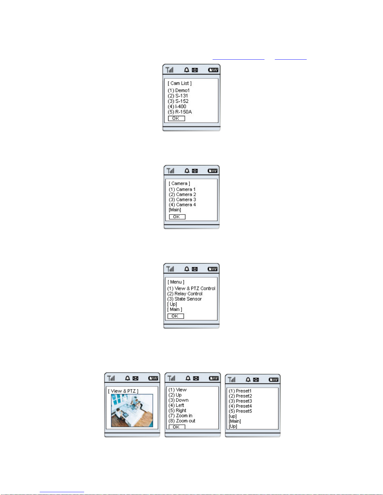
On user ID input Page [Pic.5-24], input user’s ID registered in ‘Use of PIMA Server ’ of ‘5. Basic Use’.
Pic. 5―24 List of Registered Products
Select one of the products (Camera or Server) registered by user on [Pic 5-25].
Pic. 5―25 Camera Channel
Select the Camera channel of S-160 on [Pic 5-26].
Pic. 5―26 Menu
Select a item in menu of [Pic.5-27].
9 (1) Monitoring and Control of Pan/Tilt/Zoom/Preset
Page 65
65
Pic. 5―27 Pan/Tilt/Zoom Control
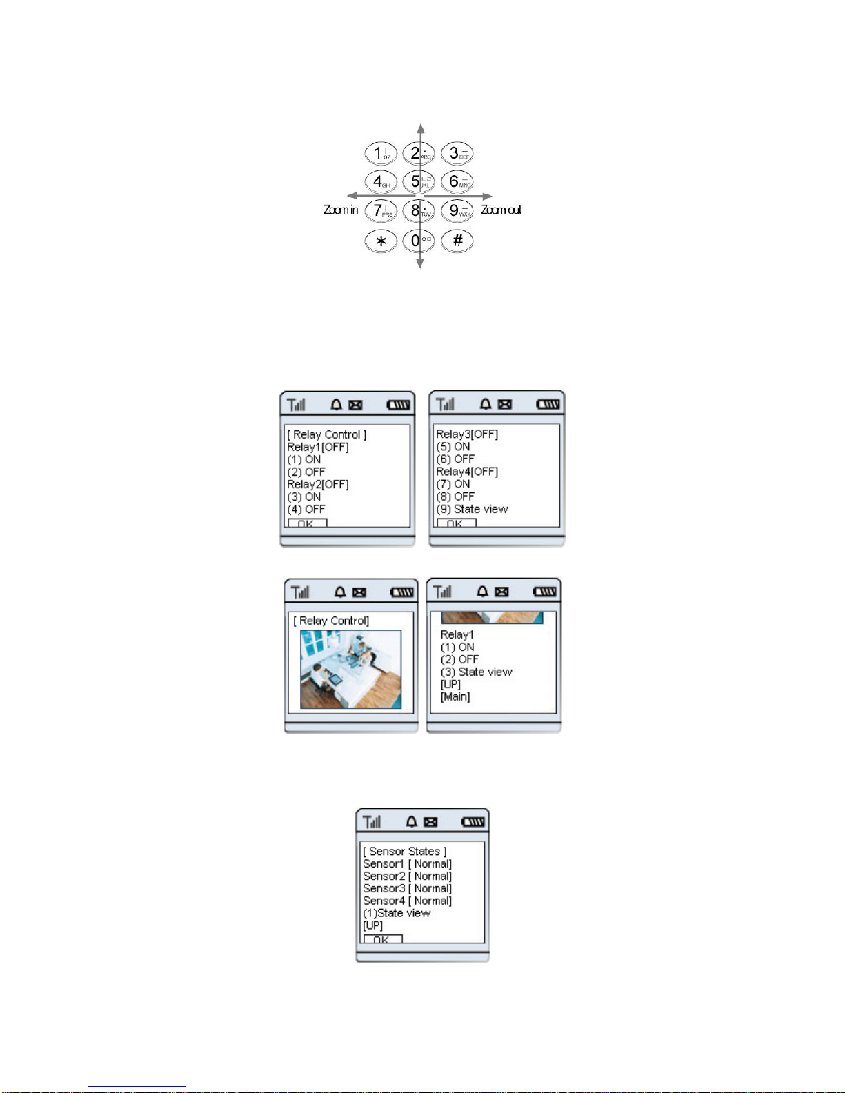
It is available to see Image and control Pan/Tilt/Zoom/Preset. Number Key of Mobile Phone controls
Pan/Tilt/Zoom.
9 (2) Relay Control (2 Relay controllable)
It is available to control up to 2 Relay. Relay Name and current status ([ON/OFF]) will be displayed.
On control of Relay, Image of controlled channel will be shown along with Relay name of the channel,
ON/OFF is to be controllable. On selecting ‘(3) State view’, current status of 4 Relays will be displayed.
9 (3) Check Sensor Status
Page 66
66
It shows the Sensor Name and current status ([Normal/Sensing]).
Connect to URL line as [Pic.5-29]. Input http://cryptotelecom.net/wml.wml
in URL input line to connect to
PIMA Server. On user ID Input Page, input user’s ID registered in ‘Use of PIMA Server
’ of ‘5. Basic Use’. The
way to use, monitor and control Image is same as one of ‘5.6.1 016,018-KTF Phone (mhtml)
’ .
5.6.2 PDA(WinCE)
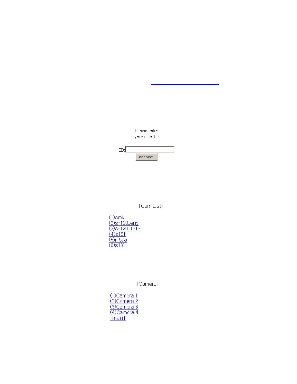
Run ‘Internet Explorer’ of PDA and input http://cryptotelecom.net/pdah5450_eng.htm
input in URL to connect to
PIMA Server.
Pic. 5―28 PDA Log-in
On user ID Input Page [Pic.5-30], input user’s ID registered in ‘Use of PIMA Server
’ of ‘5. Basic Use’ and click
‘connect’ to log in.
Pic. 5―29 Products List
Select one of the products (Camera or Server) registered by user, in Products List of [Pic.5-31].
Pic. 5―30 Camera Channel List
Page 67

67
Select a channel to see and control Image from Camera List of [5 Pic.-32].
Pic. 5―31 Menu
5.7 Use of Proprietary Viewer ( MPEG4 Communicator)
5.7.1 Required Specification of PC and OS
Item Min. Requirements Recommended Specifications
CPU
Pentium III 800 Above Pentium IV 2.0G
Main Memory
128 MB Above 256MB
O/S*
Window 98 SE. Window 2000 or XP
Web Browser I.E 5.0 Above I.E 5.0
Resolution
1,024 X 768 1,160 X 864
Network
100Base-T Ethernet 100Base-T Ethernet
5.7.2 Supported O/S
9 Windows 98 Second Edition (Korean OS, English OS, Japanese OS)
9 Windows 2000 Professional (Korean OS, English OS, Japanese OS)
9 Windows XP Professional / Windows XP Home Edition(Korean OS, English OS, Japanese OS)
9 Windows 2000 Server (Korean OS, English OS, Japanese OS)
Page 68
68
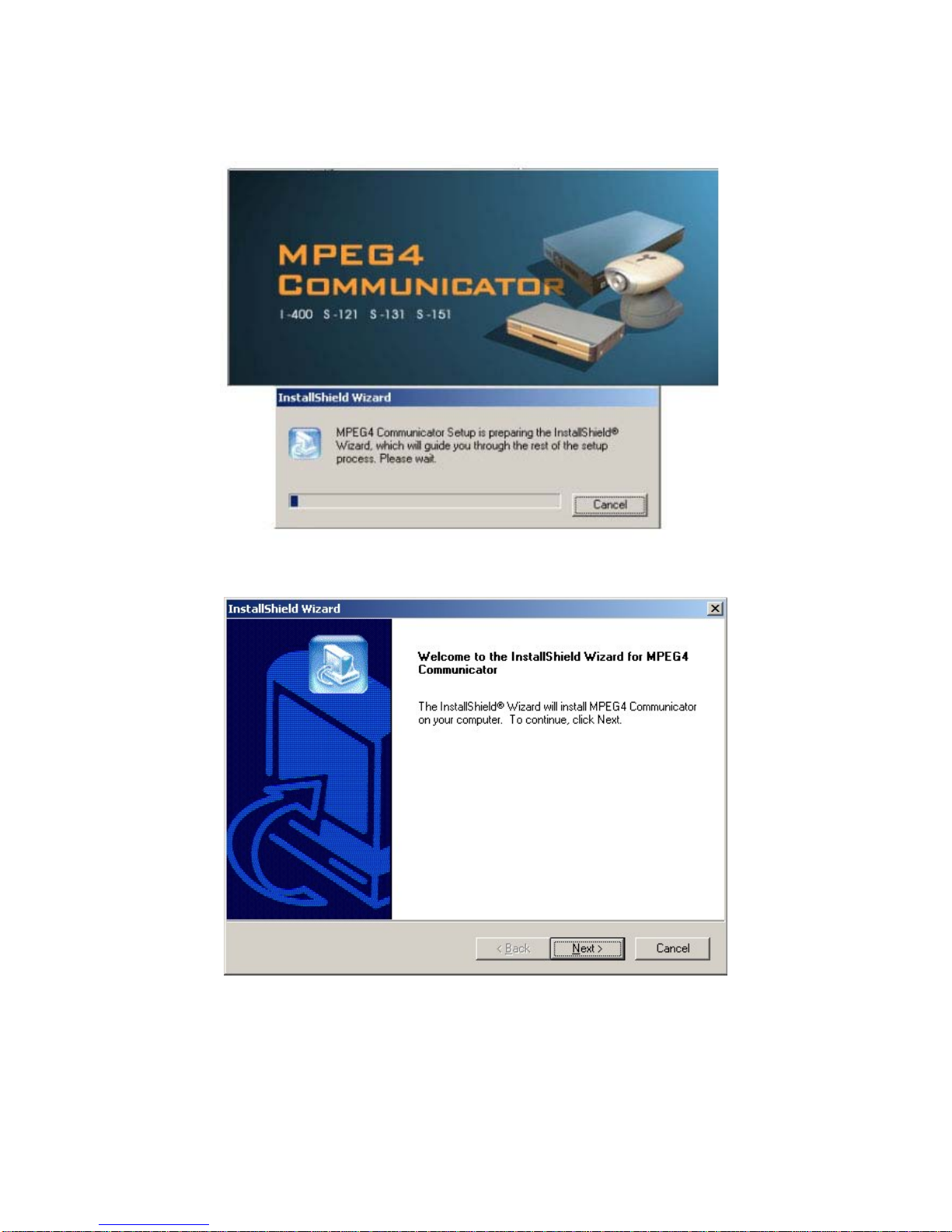
5.7.3 Program Installation
Pic. 5―32 Program Installation
Pic. 5―33 Installation
click ‘Next’ Button.
Page 69
69
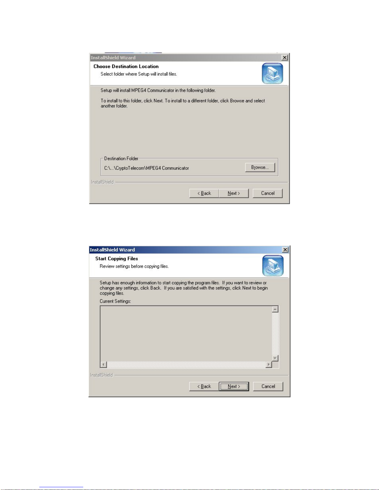
Pic. 5―34 Select Installation Folder
[Pic.5-34] is to select the folder where the program is to be installed. The route is changeable at user’s option.
To install in the default folder, click “Next” to go to the next step.
Pic. 5―35 File Copy Start
Click “Next” to start installation.
Page 70
70
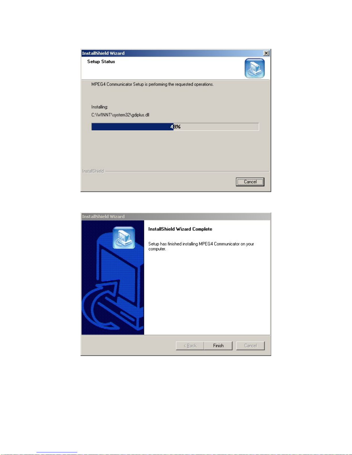
Pic. 5―36 Installation Status
Pic. 5―37 Installation Completed
Upon completion of installation, click ‘Finish’ Button.
Page 71
71
5.7.4 Use of Program
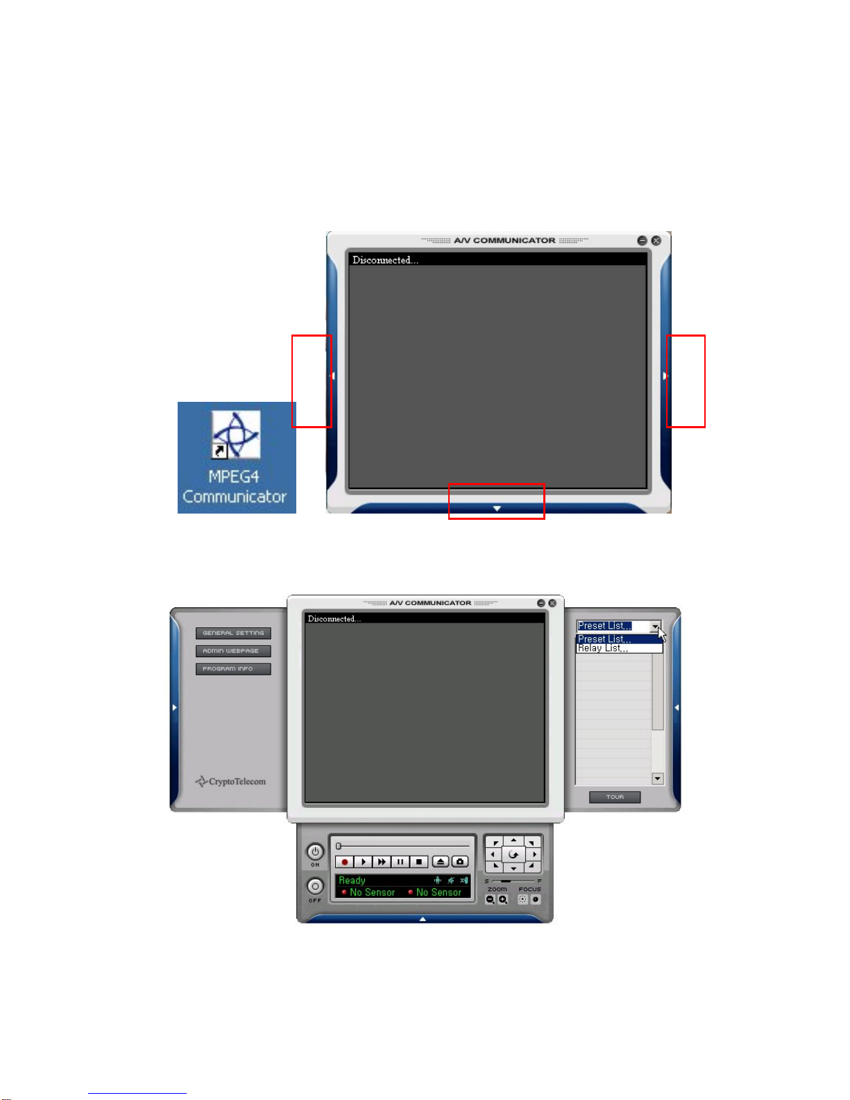
Upon installation, there will appear an icon of ‘MPEG4 Communicator’ on your PC. Double-click the icon to run
the Program, and then Program will be run as [Pic.5-38].
5.7.4.1 Viewer Screen
Pic. 5―38 Viewer Screen
Click 1,2,3, on [Pic 5-38], and then Menu of [Pic 5-39] will appear.
Pic. 5―39 Viewer Menu
①
②
③
Page 72
72
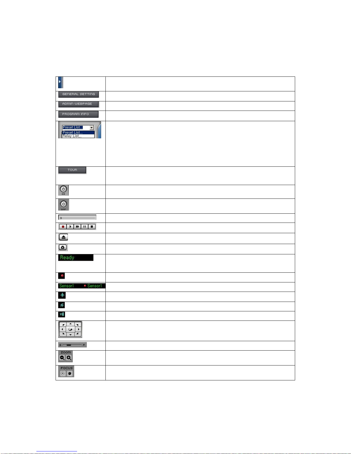
Table 5-3 Definition of Viewer Menu
Close Menu
General Menu Setting ([Pic.5-40])
Connect to Administrator’s Page of S-160
See Program Information
Move to Preset Location set in Camera, Select Relay Control
1. Preset Move
Double-click the name of Preset in the list to go to the preset location.
2. Relay Control
Control Relay by clicking ON/OFF after select the Relay name in Relay List.
Preset Tour . Move to preset location in regular sequence from No. 1 up to 20.
Move to next one after 5 seconds pause on a preset location.
Open the connection Widow to connect to S-160 ([Pic.5-39])
Disconnect S-160
Slide Bar for displaying recorded file.
Recording, Play, X2 Fast Play, Pause, Stop
Open, Search and select File ([Pic.5-42])
Capture Image on the screen
Displaying current status of Viewer
(Ready, Live: S-160 Connecting, Rec: Recording)
Flickering upon Sensor Event
Displaying Sensor name set in S-160
Flickering upon Motion Event
To connect or disconnect 1 way Audio
To connect or disconnect 2 way Audio
To control P/T of camera connected to S-160. (Pan/Tilt is controlled just by
clicking on Screen, or clicking Direction Key on Keyboard)
To control of the speed of Pan/Tilt of Camera (S:slow, F:fast)
To control of Zoom (-: Zoom out, +:Zoom in)
To control of focus of Camera
Page 73
73
5.7.4.2 General Setting Menu
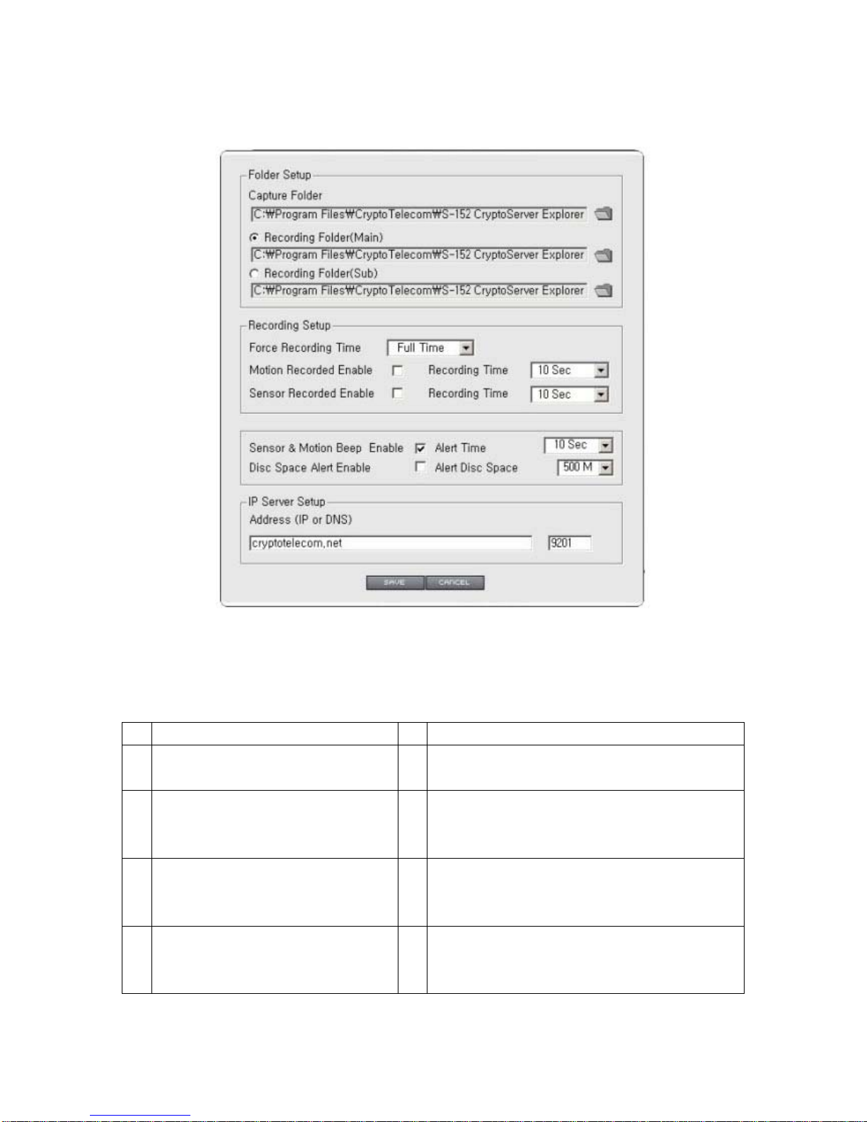
Pic. 5―40 General Setting Menu
Table 5-4 Description of General Menu
No Description No Description
1 Select the directory to capture 11 Check the warning message of Disk Space before
recording.
2 Designate the folder to record after
select the directory to save the
12 Set the disk space to display the disk space warning
on.
3 Recorded files. 13 Set the address of PIMA Server in case c onnecting
to S-160 by the MAC Address (default :
cryptotelecom.net)
4 Set the duration of passive recording (to
be recorded during the time users
selected)
14 Input Port Number of PIMA Server (Default Port :
9201)
(1)
(2)
(3)
(4)
(5)
(6)
(7)
(8)
(9) (10)
(11) (12)
(13) (14)
(15) (16)
Page 74
74
5 Record upon Motion Event. 15 Save set value
6 Set the duration of Motion recording. 16 Close Window
7 Record upon Sensor Event
8 Set the duration of Sensor recording.
9 Select the beep sound enable or not
upon event on Motion or Sensor.
10 Set the duration of beep sound upon
event on Motion or Sensor
5.7.4.3 S-151 Connection
Click ‘ON’ of [Pic.5-39] to open S-160 Connection Page.
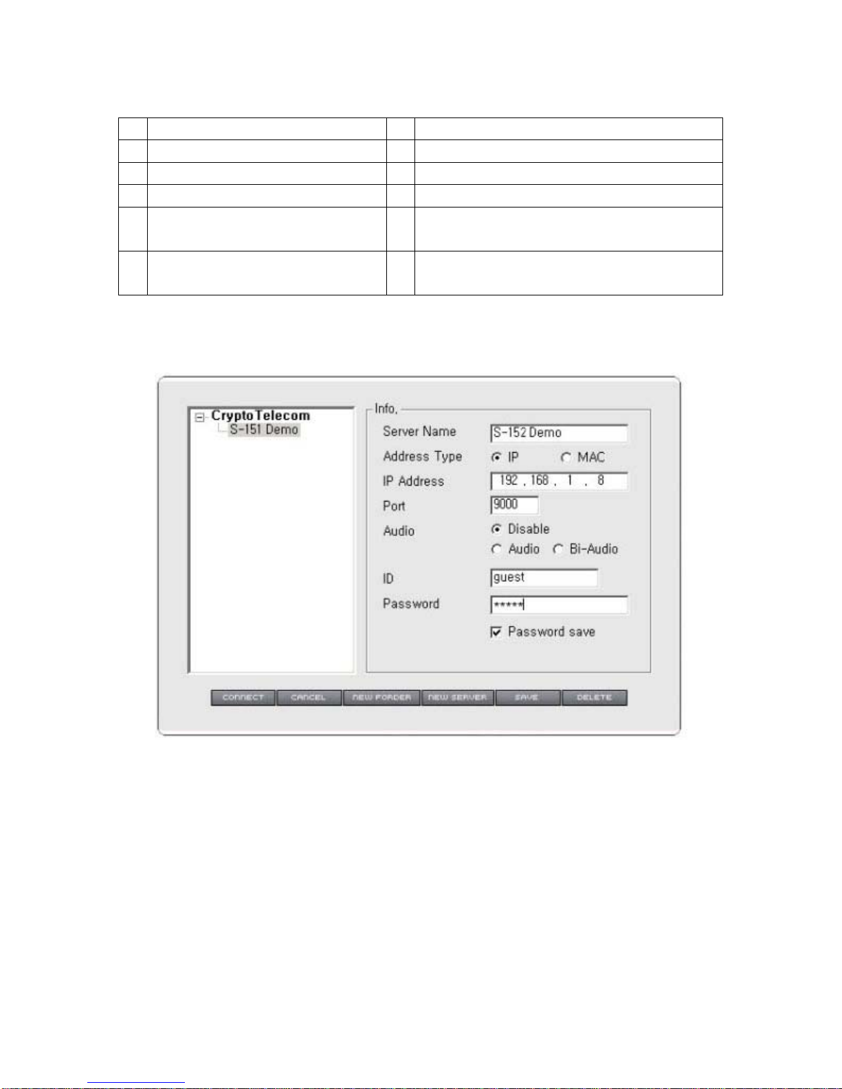
Pic. 5―41 S-160 Connection Menu
(1)
(2)
(3) (4)
(5)
(6)
(7)
(8) (9)
(10)
(11)
(12)
(13) (14) (15) (16) (17) (18)
Page 75

75
Table 5-5 Description of Connection Menu
No Description No Description
1 List of S-160 13 Connect S-160 selected in the list
2 Name of S-160 14 Close the Connection Widow
3 To connect by IP 15 Create new Folder
4 To connect by MAC Address 16 Add new Server
5 Input IP address (connection by
IP), or MAC address (connection
by MAC address)
17 Save set value
6 Input Port number for IP
connection, or channel number for
MAC address connection.
18 Delete the selected S-160 or Folder
7 Not to connect Audio
8 For 1 way audio to listen only
9 For 2 way audio communication
10 Input User ID
11 Input User Password
12 Save Password
Input the information of S-160 to be connected in [Pic.5-41] and save it. Connect to S-160 by clicking
‘CONNECT’ Button on [Pic.5-41]. It is available to control Pan/Tilt/Zoom, Preset, Relay, Audio connection
according to user’s requirements.
Page 76
76
5.7.4.4 Play of Recorded File
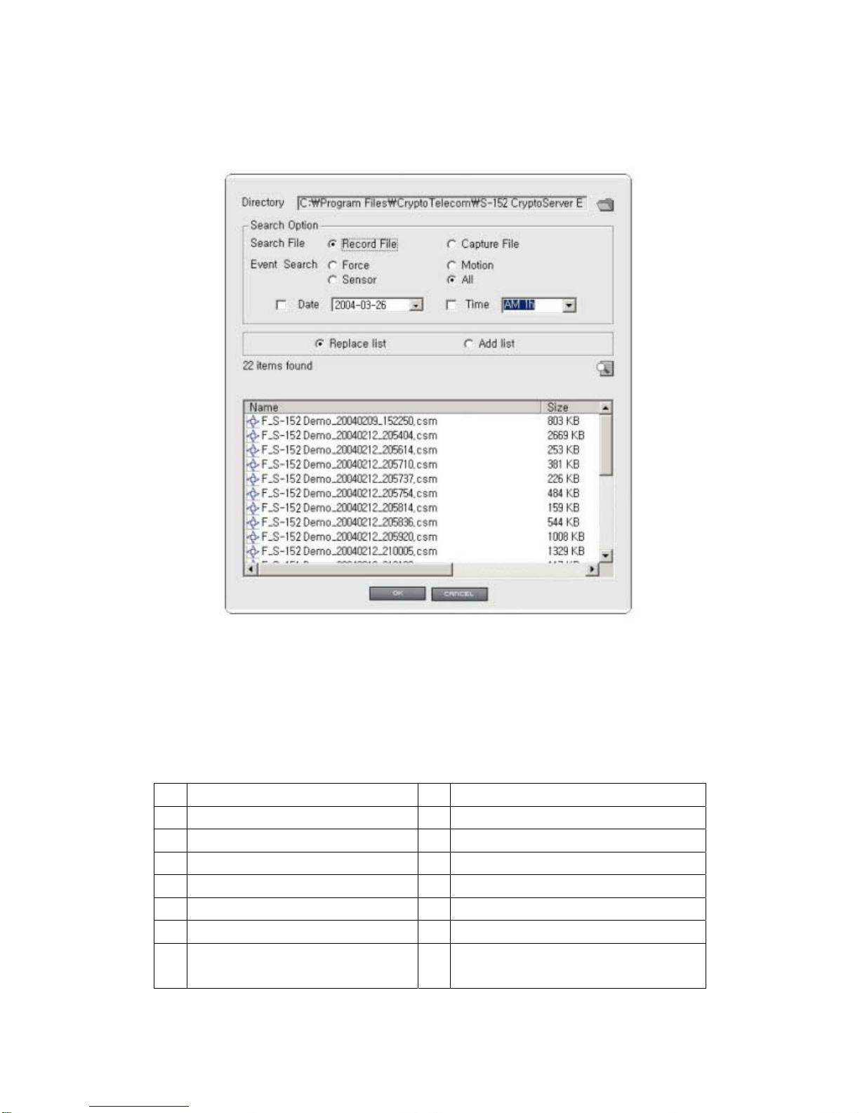
Click ‘Open File’ on [Pic.5-39].
Pic. 5―42 Play Recorded File
Tab l e 5 ―6 Play Recorded Files
No Description No Description
1 Select the folder of recorded files. 13 Search additional file on the searched list.
2 Search recorded files 14 To search file
3 Search Captured files 15 Play the selected file
4 Search passive recording files 16 Close file menu
5 Search Motion recording files
6 Search Sensor recording files
7 Search all recorded files or
Captured files
(1)
(2) (3)
(4) (5)
(6) (7)
(8) (9) (10) (11)
(12) (13)
(14)
(15) (16)
Page 77
77
8 Search files by the date
9 Select the date to search
10 Search files by the hour
11 Select the hour to search
12 Delete file list and search on new list
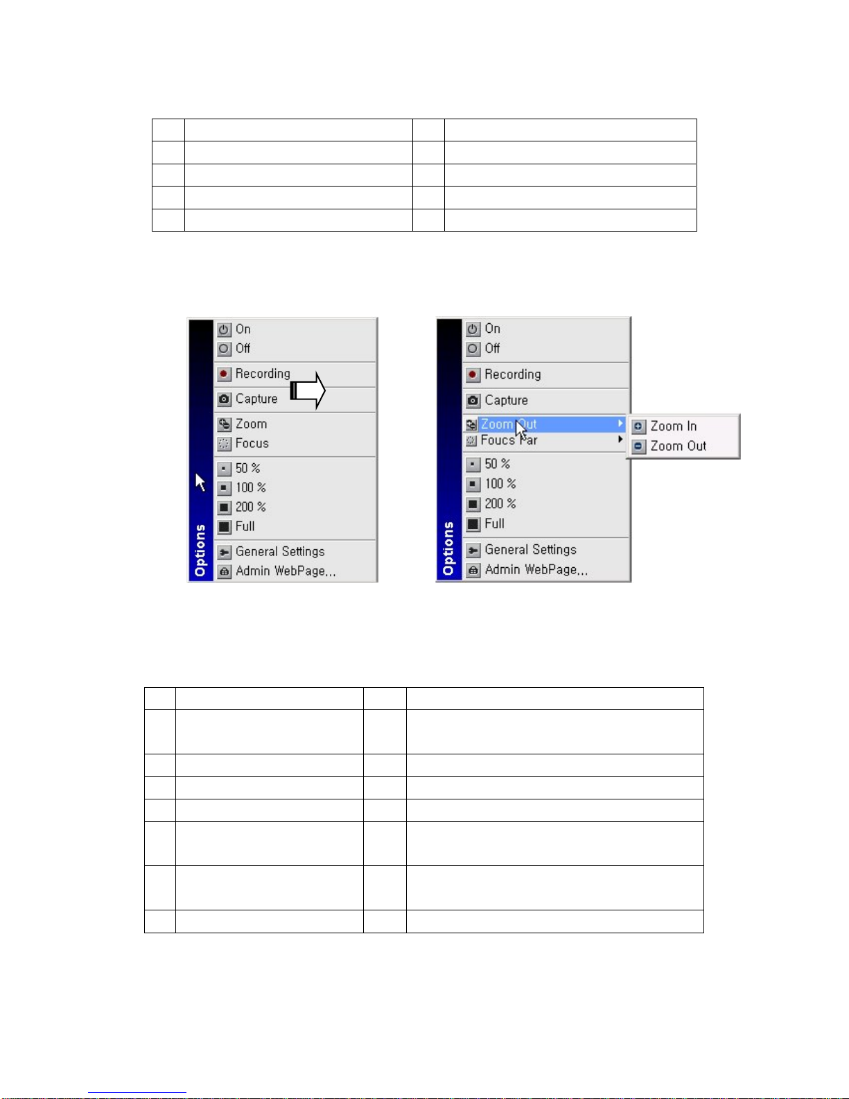
5.7.4.5 Use of Pop-up Menu
The Pop-up Menu of [Pic.5-43] will appear, upon clicking the right button on th e Screen during monitoring
Video on S-151,
Pic. 5―43 Pop-up Menu
Table 5-6 Description of Pop-up Menu
No Description No Description
1 Open the connection window
with Server List [5 Pic.-41])
8 100% Screen
2 Disconnect Server 9 200% Screen
3 Record or stop recording 10 Full Screen
4 Capture image 11 See the general setting Page ([5-40])
5 Menu to control Zoom
of Camera
12 Connect to Administrator’s Page
6 Menu to control Focus
of Camera
7 Screen size of 50%
(1)
(2)
(3)
(4)
(5)
(6)
(7)
(8)
(9)
(10)
(11)
(12)
Page 78

78
6. Network Environments
Page 79

79
6. Network Environments
It is required to follow the recommendation of the environments where S-160 will be installed or the
similar environments.
5-1. Private line Environment
Usually Company, University, Research center uses the leased line. They use many public IP addresses. In
order to install S-160 under this environment, select “Static IP Address” in ‘Static IP Setting
’ of ‘3. Basic
setting’ and input IP address, subnet mask and gateway. If there is DHCP server on the network, select
‘Dynamic IP Address’ in ‘Dynamic IP
’ of ‘3. Basic Setting’. You can get all the information (IP address, subnet
mask, gateway, DHCP server) from the network administrator . Sometimes, the S-160 may not work
properly if the user installed firewall for security purpose. In this case, open the port on the S-160, then it will
work properly. You can check the current port of S-160 from the “Administrator's Page”->”Network Setting”>”Port Setting” (see ‘3. Basic Setting
‘). The default port is set on ex-factory as follows :
¾ Web Connection Port: Port 80 TCP
¾ Authentication and Control Port: Port 9000 TCP
¾ Video Streaming Port: Port 9001 TCP
¾ 1 way Audio Port: Port 9002 TCP
¾ 2 way Audio Port : Port 9003 TCP
5-2. Broadband (ADSL, Cable, Fiber Optic) Modem Environment
Home, store, small office use one Broadband modem (DSL, Cable Modem), and use one public IP address
normally. In order to use several PC through one Public IP address, the user in most cases use IP sharing
device. We recommend using an IP router (IP Sharing device) to install the S-160. There may be a case in
no need of router, but most people use S-160 and other PC 1set or more. When using the router, connect
the router and input IP address of S-160 (IP address of S-160 is set as 192.168.1.8 on ex-factory) in DMZ
menu. If the user cannot use the DMZ function because there is no DMZ menu in the router or some other
reasons, go into port forwarding or NAT menu on the router and map the port of S-160 one by one. User can
check the current port setting of S-160 from “Administrator's Page”->”Network Setting”->”Port Setting” (see
‘3. Basic Setting
‘). Manufacturer’s setting of S-160 is as follow on ex-factory : (The user can change port if
necessary).
¾ Web Connection Port : Port 80 TCP
¾ Authentication and Control Port : Port 9000 TCP
¾ Video Streaming Port : Port 9001 TCP
¾ 1 way Audio Port : Port 9002 TCP
¾ 2 way Audio Port : Port 9003 TCP
Page 80

80
7. Appendix
Page 81

81
7. Appendix
Appendix A Basic Setting Table
Item Default (Basic Setting) Remarks
Network Setting
Static IP /
Dynamic IP Static IP
IP Server Enable
IP Address 192.168.1.8
Gateway 192.168.1.1
Subnet Mask 255.255.255.0
Web Connection
Port
80
Authentication
/Control Port
9000
Video Streaming
Port 9001
One way Audio
Port 9002
Two way Audio
Port
9003
*. Do not register the same Port.
*. Register Number with ‘9999’ or less
Some Network may not support over number
10000 port.
ID and Password
Administrator ID
/Password
admin/admin
User ID root/root, guest/guest
Domain of Related Server
IP Server cryptotelecom.net Domain of Server to connect to register IP
Alarm Server cryptotelecom.net
Domain of Server to connect to send Event upon
detection of Sensor or Motion.
Upgrade Server cryptotelecom.net
Domain of Server to connect to download
upgraded program
Plug-in Download
Server cryptotelecom.net
Video Setting
Compressed
Resolution 704*480
Video Format NTSC/PAL
Page 82

82
Frame Rate 15fps
Bit Rate 200kbps
Other Setting
Time Zone Asia/Seoul(Korea)
*. Note : In case to reset Hardware and Network Setting, ID and Password of User and Ad mini s trator will
be automatically returned to the above default value.
Appendix B Specification of Products
Item Specification Item Specification
Summary
OS Linux CPU ARM 200MHZ
Network
Interface
RJ45 10/100BaseT Setting IP Setting : Proprietary Program
Other Setting : by Web Browser
Network
Support
Leased Line, Cable
Modem, HomePNA
Support Dynamic IP
and Static IP
Usable under Router
for ADSL
Web
Server
User Homepage Upload and Saving
Function
Server Setting Function
Web Viewer Download Page
Supporte
d Protocol
HTTP,FTP,TCP/IP, DHCP, ARP, DNS, ICMP Viewer
Software
Compatible
WINDOWS 98,SE
WINDOWS 2000,
WINDOWS XP,
WINDOWS NT
Security USER AUTHENTICATION
Operation Environment
OperationTemp
.
5 ~ 40℃
Storage
Temp.
-10 ~ 70℃
Humidity 20-80% Relative
Humidity
Location INDOOR ONLY
Case
Size 222mm[W]*148mm[
D]*38mm[H]
IMAGE
Compression MPEG-4(SIMPLE
VIDEO ROFILE)
Resolution 704*480,352*480,
352*240
Frame
Rate
30FPS[max]
Bit Rate 100kbps ~ 500kbpS Compres
sion Rate
200:1(Typical)
Page 83

83
Video Format NTSC/PAL
Input / Output
Digital In 2Port – Open/Close
Input
Digital Out
2 Ports – Relay Open/Close
Normal Open
Max current :0.5A
Max voltage :240VAC
Peripheral device
Communication
RS232 1Port, RS485
1 Port
(select one of them)
Ethernet RJ45
Video Input BNC Jack Video
Output
BNC Jack - Loop Th rough Out
Function and Features
Simultaneous
Access
Max. 50 users (under
10
Users
recommended)
Alarm
Mode
Function
Detect Sensor Input and Drive Event
Viewer Proprietary Viewer,
and Web
Plug-in Viewer to be
downLoaded from remote
server
Video
Recordin
g
Recording in Viewer or FTP Server upon
Alarm Event
Web Page Upload of user Web
Page
Through FTP
E-mail
message
Send E-mail in Alarm Mode upon Event
Dynamic IP Support IP Router Support
Hardware
Reset
In case user forgets
Administrator’s
Information
and can’t change
camera setting,
Administrator’s ID
and Network
Information is
to be reset on default
value
SMS Short Message Service through Alarm
Server upon Event
Electronic Specifications
Adapter Input : 100/220VAC ,
Page 84

84
Ootput :12V/1.5A
Appendix C To solve problem
C-1 Basic Check-point
C-1-1 Booting
z Check if power plug is connected correctly.
z Power Cable : Use cable for S-160, contained in Product box.
z Power LED : The front left LED twinkles on upon supplying Power.
C-1-2 Network cable (LAN cable) and cable connection check
z Check if network cable is straight LAN cable. Hold each end of both side and check if same color ’s cable
is connected to same location in RJ-45 jack or not.
z Check if network cable connects correctly with S-160.
z Check if network cable connects correctly with Hub, IP sharing device and cable modem etc….
C-1-3 CCTV camera
z Check if video cable of camera is connected correctly with Video-in port that is located in the rear side of
the server.
z If video doesn’t appear even though connection is correct, connect camera with CCTV monitor or video-
in port of TV and check if video can be seen.
*. If you found a problem in the product, first check with “C-1 Basic check point” and solve the problem
as following procedures:
C-2 Troubleshooting by type
C-2-1 Cannot connect with network
z Check with ‘C-1-2 Network Cable (LAN cable) and cable connection check’.
z PING Test
In case Camera uses Static/Public IP: input “Ping IP address” to command window of PC and check
response.
In case user cannot find camera IP address when camera u ses dynamic/public IP, reset hardware
and connect PC with S-160 through cross cable and ping test by entering “192.168.1.8”.
In case camera uses private IP through IP sharing device: do ping test of private IP address set for S-
160 in PC that is connected in the local network through IP sharing device.
z If “ping test” get response, network setting for camera is done correctly.
z If ping test is okay but there is no connection, check with ‘C-2-2 check port setting’.
C-2-2. Check Port Setting
z If user can’t connect with camera even though ‘Ping test’ is okay, please check port setting by the
Page 85

85
following steps.
z S-160 uses 3 ports as follow.
¾ Web Connection Port : Port 80 TCP
¾ Authentication and Control Port : Port 9000 TCP
¾ Video Streaming Port : Port 9001 TCP
¾ One way Audio Port : Port 9002 TCP
¾ Two way Audio Port : Port 9003 TCP
z If it is not available even to connect to web, check web connect port because web connect port may be
set with other number than ‘80’.
z In case there is problem in video monitoring even though there is no problem in Web connection, check
if ‘Authentication and Control Port’ and ‘Video Streaming Port’ of S-160 is set on IP sharing device (in case
of using IP sharing device).
z For setting of IP sharing device Port, refer to ‘IP sharing device setting’.
z In case web page can’t be connected under super highway internet line, some super highway ISP
company may block the use Web port number 80. In this case, change to other number from web
connection port setting.
Appendix D Serial port (RS232c) explanation and example
D-1 Pin Number
D-2 Pin Signal
No 1 : Not Used
No 2 : RxD
No 3 : TxD
No 4 : Not Used
No 5 : GND
No 6 : Not Used
No 7 : RTS
No 8 : CTS
No 9 : Not Used
D-3. In case of connection with and control of “Analog Pan/Tilt/Zoom Camera [VC-C4R]” of Cannon.
S-160 (VC-C4R)[Canon’s Analog P/T/Z Camera]
9`Pins 8Pins
1 2 3 4 5
6 7 8 9
Page 86

86
DSUB(Female) Mini DIN Connector
Shield
Shell Shell
1 NC
2 RxD 3 TxD
3 TxD 5 RxD
4 NC 6 GND
5 GND 4 GND
6 NC 7 NC
7 RTS 2 CTS
8 CTS 1 RTS
9 NC 8 NC
 Loading...