

Page 1
EB30/EC30/630 Upgrade Page 1
Commercial Vehicle Roller Brake Tester.
EB30/EC30/630 Upgrade
OPERATING INSTRUCTIONS TES1343/A
July 2001
Page 2

EB30/EC30/630 Upgrade Page 2
IMPORTANT
Every reasonable effort has been made to ensure that information within these Operating Instructions is correct
at the time of release, but Crypton cannot accept-responsibility for any errors that may occur.
The information in these Operating Instructions is subject to change without notice, and does not represent a
commitment on the part of Crypton.
Service & Warranty
The reliability of this equipment is fully supported by our service agent.
Please refer to the page at the end of this manual for full details.
Note:
Your attention is drawn to our Terms & Conditions of Sale, particularly paragraph 2. If a service engineer is
called out. under service warranty where, upon inspection and test the equipment is found to be in full working
order and no fault found, the user is liable to be charged the cost incurred for this call out. Before calling out
an engineer, ensure your equipment is faulty by checking its operation, particularly mains supply and fault
codes/self test if applicable.
WARNING:
Do not attempt to operate this equipment unless you have read and understood these
instructions.
Page 3

EB30/EC30/630 Upgrade Page 3
Index:
Safety procedures for brake testing procedures 2
Description 3
Functions and Facilities 6
PC Brake Diagnostic Program 9
The Theory of Brake Testing 12
Preparing for a Brake Test 14
Automatic Test Procedure (NOT MOT) 15
Manual Brake Test Procedure for Commercial Vehicles (MOT) 17
Manual Brake Test Procedure for Class IV and Class VII (MOT) 23
Maintenance 28
Trouble shooting 31
Terms and conditions of sale 32
After sales service 35
Notes 35
Page 4

EB30/EC30/630 Upgrade Page 4
Safety procedures for brake testing
! Notice the location of the emergency stop. The switch is located in the
immediate vicinity of the brake tester.
! Read this user’s manual thoroughly before attempting to operate the brake
tester.
! Keep this user’s manual in an easily accessible place.
! Never touch the rollers when the tester is in operation.
! Do not press the third roller down with your hand, foot or any kind of tool.
! Unless authorised, do not remove or make any alteration to any part of the
tester. Contact the supplier.
! Do not use the brake tester for any other purpose than for which it is intended.
! The brake tester must not be used in environments susceptible to explosions.
! Keep unauthorised persons away from the rollers and the wheels of the vehicle
during operation of the tester.
! During service and repair of the tester: Switch the tester off and lock the switch.
! The brake tester will always stop when pressing STOP.
After having pressed STOP, the brake tester can only be restarted by pressing
START or by driving a wheel set onto the roller unit.
! Pressing the emergency stop will stop the brake tester immediately. To restart:
pull the emergency stop back and press the reset key.
! For brake testers fitted with emergency light beam circuit breaker in the pit:
Braking the light beam will stop the brake tester. Reset by pressing the reset key.
Page 5
EB30/EC30/630 Upgrade Page 5
Description
Main components
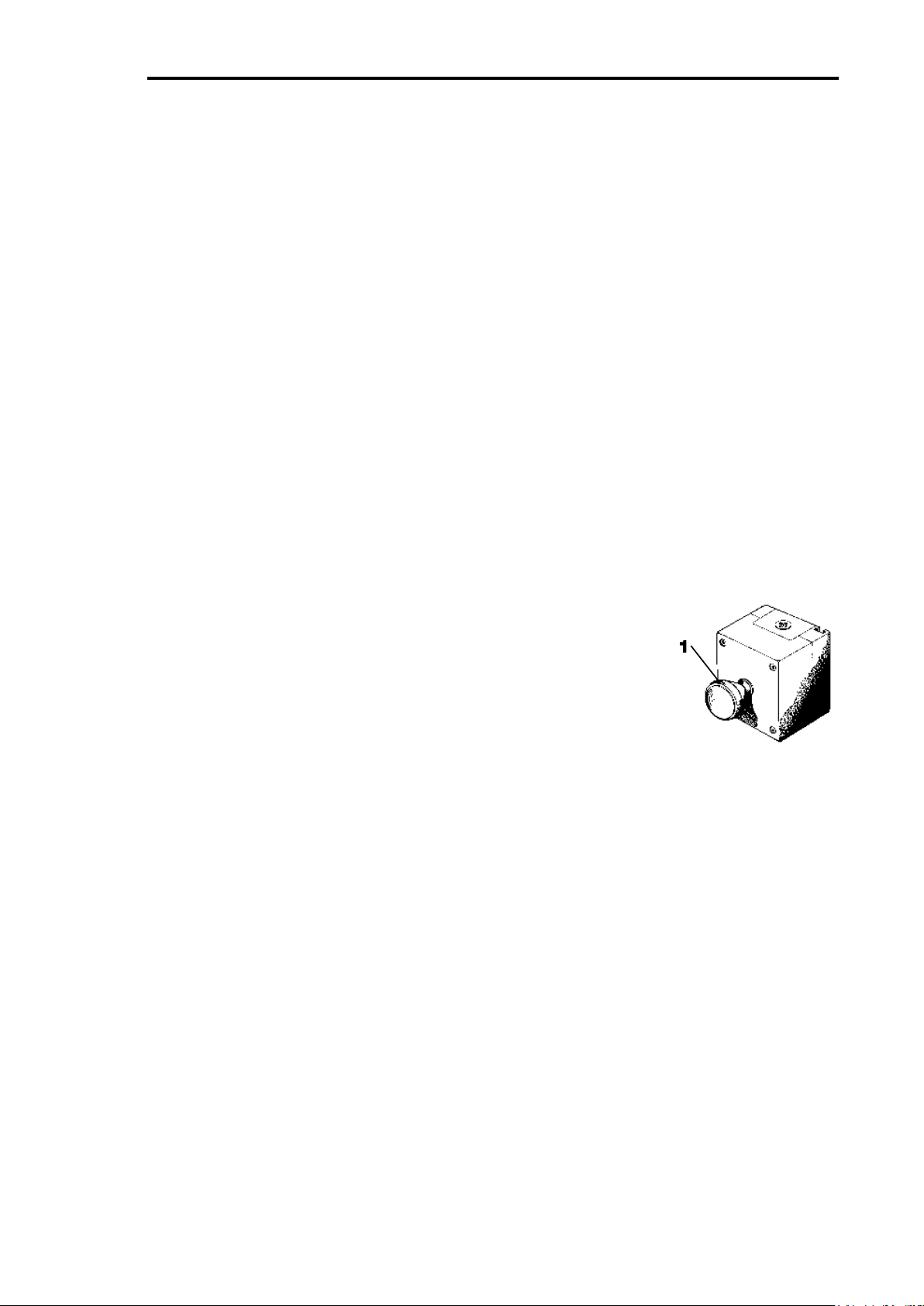
1. Emergency stop
2. Display console.
3. High voltage control unit.
4. Roller unit.
5. PC with brake diagnose program
6. Printer
7. Remote control
Accessories:
Base station for wireless air pressure transducers
Air pressure transducers - wireless
Air pressure transducers - cable connected
1. Emergency stop
Press for emergency stop.
Note: Notice the location of the emergency stop before
starting the brake tester. The emergency stop is not
necessarily positioned in the same place at every installation,
however it will always be installed in the immediate vicinity of
the brake tester.
Page 6
EB30/EC30/630 Upgrade Page 6
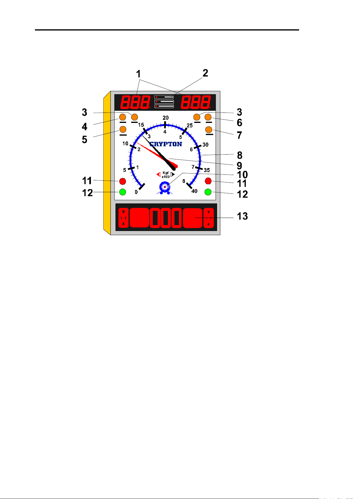
2. Display console
1. Top digital display - air pressure, ovality and weight
2. Indicator showing type of information on top display
3. Indicator light - 4WD (accessory)
4. Indicator light - automatic operation
5. Indicator light - manual operation
6. Indicator light - scale range or 0-800 Kgf)
7. Indicator light - scale range 0-4000 Kgf)
8. Scale showing brake force
9. Pointers; red = left, black = right
10. Amber light - zeroing and fault indicator
11. Red lights - wheel locking
12. Green lights - ready for testing
13. Bottom digital display - imbalance, ovality, pressure and weight
Page 7

EB30/EC30/630 Upgrade Page 7
3. High voltage control.
1. Keyboard.
2. RESET button (resetting of safety relay).
3. Main switch (power supply circuit breaker).
4. Roller unit.
1. Rollers
2. 3rd roller
Fitted with:
Strain gauge transducer.
Speed sensor on third roller.
Speed sensor on gear box
Proximity sensor on third roller assembly
5. PC with diagnostic program
1. On/off switch
2. PC keyboard
3. Monitor
6. Printer
1. On/off switch
2. Paper tray
3. Cover
7. Remote control
1. Keyboard
2. Battery cover
3. Infrared transmitter window
Page 8

EB30/EC30/630 Upgrade Page 8
Functions & Facilities
The functions and facilities of the brake tester in alphabetical order.
Automatic operation (not for UK MOT use)
In automatic operational mode, the brake tester will start automatically when a
wheel set is driven onto the rollers and stop either when the wheels lock, when stop
is pressed or when driving out of the rollers.
When the brake tester is turned on it is in automatic mode.
It changes to manual mode when registering a vehicle on the PC.
It returns to automatic operational mode after having concluded a test
or after having pressed PRINT.
If STOP has been pressed so that the AUT and MAN lights are lit.
The brake tester will not start up automatically when driving a wheel
set onto the rollers. Then press STOP again before driving onto the
rollers.
Imbalance
In manual operational mode: Press DAFF after having started the rollers. The
difference of braking effect between the left and right wheel is indicated by the
positions of the pointers. The result is shown at the bottom display (as %).
In automatic operational mode: The imbalance is shown when the brake force
exceeds 40 kgf.
You toggle between imbalance and air pressure by pressing AIR and DAFF.
One-wheel operation (accessory).
In one-wheel operation one wheel is rotating whilst the other is stationary.
Press TEST and START. Choose the wheel by using UP for the left wheel and
DOWN for the right one. The display shows which one has been chosen. Press
START to start the chosen wheel.
One wheel operation is used for MOT testing and to test damaged vehicles.
Four-wheel operation. (accessory).
The brake tester can be fitted with a facility to test four-wheel drive vehicles. This
makes it possible to test one wheel whilst the other wheel on the same axle is
reversing to avoid that the torque is transmitted to other axles during the test.
Brake force is measured only on the non-reversing wheel.
Press 4WD. Drive the first set of wheels onto the rollers and press START. The
green light lights up on the side of the wheel to be tested and the relevant pointer
shows the brake force. Press OK to store the result. Press START to test the other
wheel and press OK to store the result.
Page 9

EB30/EC30/630 Upgrade Page 9
Choose which wheel to be tested first before starting the test: Press 4WD once to
choose the left wheel (indicated by the left light). Press 4WD again to choose the
right wheel to be tested first. Press a third time to return to normal operation.
Parking brake.
The parking brake is tested in the same way as the foot brake. It is therefore not
necessary to make special concessions for testing the parking brake.
However in manual mode it is necessary to indicate when the parking brake is to
be tested. The reason is that special calculations are used for the parking brakes.
With a wheel set on the rollers press START and choose the transducer using the
UP and DOWN keys. Press START again to start the rollers. Press PARK to
indicate the test of the parking brake.
The bottom display shows momentarily the number of the relevant parking brake,
for example P1. Then the bottom display shows the pressure P
The top display
M.
shows the chosen pressure Pc.
Printed report.
A report can be printed after a test in manual operational mode. Press the PRINT
key after the last axle has been tested and accepted.
The report shows all relevant calculations both of each individual axle and of the
whole vehicle. The report can also contain relevant graphs.
The content and layout of the report is set up in the program on the PC.
Holding the result on the display.
In both manual and automatic mode the pointers and the LED displays will remain
showing the results after locking the wheels until either restarting the tester,
pressing OK or after 5 minutes have elapsed.
Page 10
EB30/EC30/630 Upgrade Page 10
Symbols.
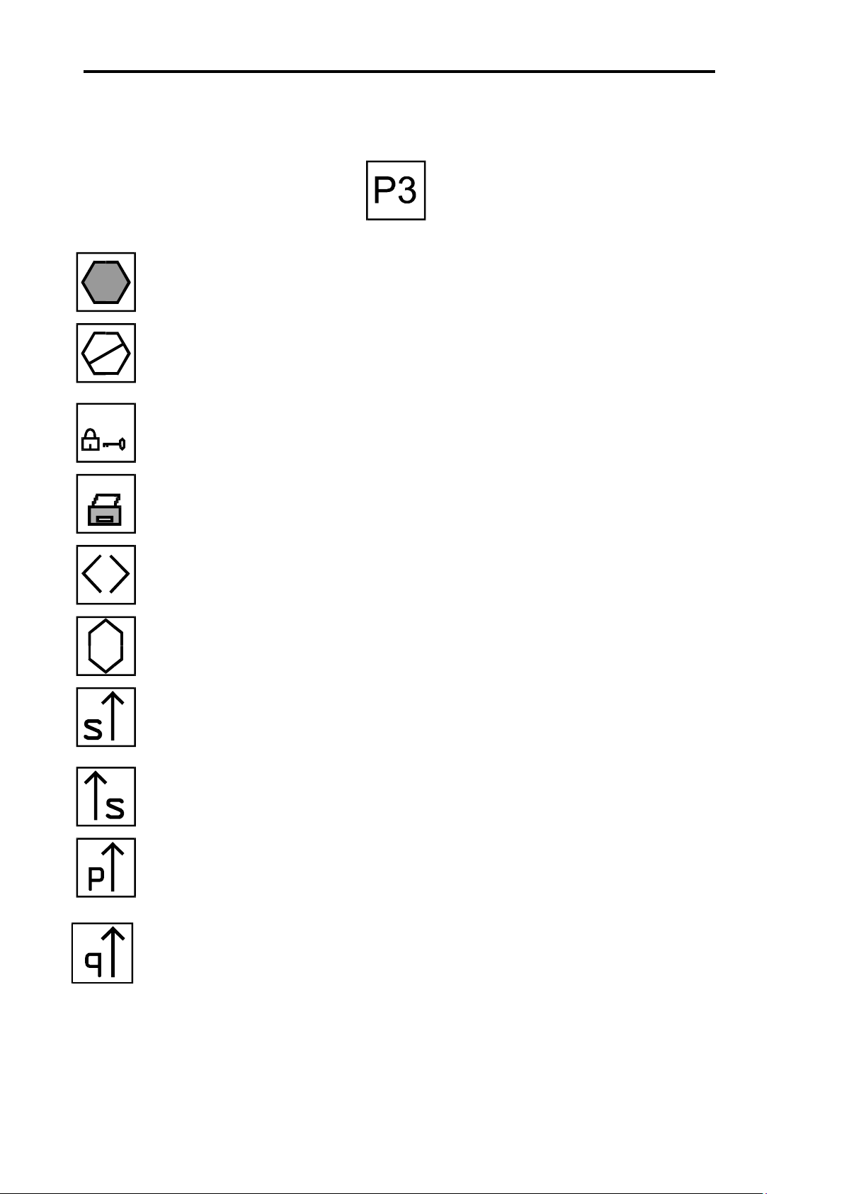
The following symbols will appear on the LED display:
Parking brake and number.
Accept of signal from remote control
Emergency stop activated
The brake tester is locked and does not communicate with PC
The brake tester transmits signal to printer
Imbalance in %
Ovality in %
Testing left secondary brake.
Testing right secondary brake
Testing left parking brake.
Testing right parking brake
Page 11

EB30/EC30/630 Upgrade Page 11
PC Brake Diagnostic Program
With diagnostic program, the performance of the brakes of a vehicle can be
analysed in details. The results can be analysed graphically in many ways and
stored for later comparison. The program is very user friendly and supported by a
comprehensive help system. Pressing F1 will provide the answers to most
questions. The text in the help program is dependent upon the content on the
screen and provides clear and relevant answers.
The program is easy to use. Choose menu items and buttons on the screen with
the arrow keys and press ENTER. Fill in the cell on the screen with the
specifications you are asked for by the program (You will find the instructions on
the bottom line of the screen). This insures correct and easy use.
Registration of a vehicle.
For manual testing of a vehicle it must be registered on the PC. If the vehicle has
not been tested on the brake tester before, it is necessary to key in some
specifications. If it has been tested before a lot of the specifications are stored in
the program and can easily be transferred to the new test.
Choose BRAKE TEST on the menu. If the vehicle has been registered before on
the tester, choose OPEN VEHICLE DATA and find the registration number on the
list.
If the vehicle has not been registered before:
Choose “ENTER VEHICLE DATA” and fill in the form on the window:
Name: (name of owner of vehicle) optional
Address: (address of owner) optional
Address: (address of owner) optional
Zip Code: (postal code) optional
City: (town) optional
Telephone no.: (Customers phone no.) optional
Job no.: (Internal job no.) optional
Tested by: (Initial/name of operator) optional
When the key-in data are satisfactory, choose OK.
Choose the relevant type of vehicle.
Choose “Other brake type”
Choose whether or not a trailer is hitched.
A new window appears:
Page 12

EB30/EC30/630 Upgrade Page 12
Make: (Make of vehicle) Obligatory
Reg. No. (Registration no) Obligatory
Man. year (Year of manufacture) Obligatory
Gross vehicle weight (maximum allowed weight) Obligatory
Actual vehicle weight (Weight at time of test) Optional
No. of axles: (Number of axles to be tested) Obligatory
Mileage: (Mileage at day of testing) Optional
Remarks (Any relevant remark) Optional
When the data of the vehicle has been opened or keyed in they must be
transferred to the brake tester. Choose START BRAKE TESTING from the main
menu. Perform the brake test as described in the chapter "Brake testing, manual
mode"
After the completion of the test, the results can be printed out on a colour printer
and/or processed graphically on the PC - see below.
Printouts
A series of printouts can be performed on the colour printer.
You can choose between a:
Graphical processing of the results.
The results can be studied in details by using the graphical facilities in the PC
program. The results can be analysed immediately after the test, or data from an
earlier test can be called from the memory of the PC.
After the completion of the test you can choose between the before mentioned
user designed standard printout set-up or a specially designed printout. The user
designed printout is described in menu point CONFIGURATION - STANDARD
PRINTOUT. The special designed printout is described in a similar menu. Choose
the desired specifications by marking them with " " using the space key for setting
or removing the tick.
You can choose from different types of graphs, tables and calculations in the PC
program:
Brake force - PC graph -when air pressure has been measured
For each axle the brake force is shown as PC . The graph shows the relation
between the brake force and the pressure in the cylinder on each axle. This will for
example detect defective valves.
Time graph -when air pressure has been measured.
For each axle the graph shows the brake force and air pressure as they are
developing with time elapsed. If the brake pedal was released whilst the display
showed "U" the thick line shows increasing brake force whereas the thin line shows
the brake force when releasing the brake pedal.
PC - PM graph -when air pressure has been measured.
The graph shows the development of the air pressure in the cylinder in comparison
with the pressure in the main line. The pressure in the cylinder is shown on the Y-
Page 13

EB30/EC30/630 Upgrade Page 13
axis and the main line pressure on the X-axis. -The graph is used for analysing the
function of the reduction valve.
Retardation graph -when air pressure has been measured.
The retardation graph shows the main line pressure on the X-axis and the
retardation on the Y-axis
Result as table.
The table shows all recorded values of brake force and air pressure. The results
are projected on line with the values recorded simultaneously on the same line.
Results summary.
The result summary shows the vehicle’s braking performance and forces at the
point of locking together with the calculated ovality, imbalance and retardation.
Page 14

EB30/EC30/630 Upgrade Page 14
The Theory of Brake Testing.
Brake testing on roller brake tester.
Measuring the brake force is done as described in the following: An asynchronous
motor turns the wheels of the vehicle. The brake force of a wheel affects the rollers
with a torque, which is measured electronically. The torque is in proportion with the
brake force, which therefore can be shown on the dial display with a high degree of
accuracy.
Brake test on rollers offers several advantages:
Imbalance.
Imbalance is the difference in brake force between the right and the left wheel on
the same axle. The imbalance is measured progressively during the test and is
converted into % before it is shown on the display.
The imbalance in % is calculated as the difference in % of the highest actual brake
force. For example:
Class IV and Class VII:
If, in a given time the brake force on the right side is 200 kgf and on the left
side is 220 kgf. The difference is 220 -200 = 20 kgf. Must not exceed 25%
The highest brake force is 220 kgf. The imbalance is then:
220 -200 x 100 = 9%
220
HGVs and PSV:
On commercial vehicles the imbalance is the difference between the brake
force measured at the time of locking of the wheels on the same axle. It is
only obligatory to measure imbalance on the steering axles (MOT
regulations).
The imbalance on the steering axle on commercial vehicles must not exceed
30%.
If the imbalance is too great, the vehicle will have a tendency to be drawn to the
side with the highest brake force when applying the brakes. In critical situations a
sideslip is eminent.
Ovality.
Ovality is a description of varying brake force measured during one revolution of a
wheel at a constant brake pressure. Often this is caused by oval drums or uneven
brake discs. Ovality can also indicate broken or rusty drums or discs. The values is,
like brake force, measured as kgf. However it can also be shown as a percentage
of the actual brake force.
MOT does not accept an ovality of more than 70%.
Brake Pedal Pressure. (Available as accessory).
Page 15

EB30/EC30/630 Upgrade Page 15
The pressure asserted by the foot on the brake pedal is called the brake pedal
pressure. Especially interesting is the highest brake pedal pressure measured at
the moment the wheels lock. The highest brake pedal pressure must be less then
50 - 70 kilos depending on the type of vehicle. Greater brake pedal pressure can
be caused by worn brake pads or for example defective brake booster or reduction
valves.
Rolling Resistance.
The rolling resistance is the brake force measured during a test without activating
the brake pedal. Dragging brakes, maladjusted brakes or defective valves can
cause this. A high rolling resistance can cause considerably wear of the tyres, and
on the brake pads and can result in higher fuel consumption.
Calculated brake force.
It may not always be possible to measure the maximum brake force on a roller
brake tester. The reason for this is that the point of locking of the wheels will be
reached sooner if the vehicle is not fully laden. It is therefore necessary to calculate
the brake force at a higher pressure. The calculation is done using the measured
maximum brake force, the measured maximum pressure and the allowed total
weight of the vehicle. This calculation will reveal how the vehicle’s brakes will
perform during an emergency stop.
Gross vehicle weight.
This is the allowed maximum weight of the vehicle and payload according to the
law.
The maximum weight is noted in the vehicle’s registration papers. This weight is
being used for the calculation of the braking ability of the vehicle.
Guaranteed pressure.
The guaranteed pressure is the lowest legal level of the highest attained pressure
at maximum braking action. This pressure is also used for calculating the braking
ability of the fully laden vehicle.
PC-pressure. When air transducers are fitted.
The pressure measured in a brake cylinder when being tested.
PC-start pressure. When air transducers are fitted.
The pressure measured in a brake cylinder at the moment braking effect begins.
PM-pressure. When air transducers are fitted.
The pressure measured in the main air line leading to the trailer. For vehicles with
Duomatic valve this pressure is called the duomatic pressure.
Page 16

EB30/EC30/630 Upgrade Page 16
Preparing for a Brake Test.
Turn the power on at the main switch of the brake tester and press RESET.
Turn the power on by turning the switch to "I". Press the RESET button, which is lit
up. This turns on the safety system.
Do not drive the vehicle onto the rollers until the amber zero indicator is turned off.
The brake tester cannot operate as long as this light is lit.
During this procedure the brake tester checks the electronic system and zeros the
settings. When the tester is not in use the zeroing is performed at regular intervals
with only seconds apart.
.
When the amber light is turned off the brake tester is ready for use.
It is in automatic mode for a quick test.
For manual mode, register the vehicle on the PC before driving it onto the rollers.
Page 17

EB30/EC30/630 Upgrade Page 17
Automatic Brake Test Procedure.
- NOT ALLOWED FOR MOT TESTING!
Automatic operation provides the following advantages:
The brake tester starts automatically when a wheel set in driven onto the rollers
and is stopped either when the wheels lock or when the wheel set is driven out of
the rollers, or manually by pressing STOP.
The brake tester will start up in the automatic mode and remain here if no vehicle is
registered on the PC. The tester is always left in automatic mode after conclusion
of a test.
Note. Automatic mode does not provide many facilities such as registering the
vehicle, measuring air pressure nor is the analytic facility available.
Automatic operation is a way of performing a quick and simple test on all types of
vehicles, and recommended when that is all, which is required.
Testing Procedure:
1 Drive the first axle onto the rollers.
2 Wait for start and green light.
3 Measure ovality at 100 - 500 kgf.
4 Slowly increase the brake force.
5 The brake tester stops automatically when the wheels lock.
6 Tests the parking brakes.
7 Repeat the test on the remaining axles.
1 Drive the first axle onto the rollers.
The bottom display shows "U" for each wheel placed on the rollers. Both
wheels must be on the rollers before the brake tester will start.
2 Wait for start and green light.
A moment after the wheels have been placed on the rollers, the brake tester
will start automatically. When the tester is ready the red lights will turn off and
the green lights will turn on. Do not assert pressure on the brake pedal until
the green lights are turned on.
Before pressing the brake pedal the pointers show the rolling resistance.
When applying the brakes the pointers show the brake force, whereas the
bottom display shows the imbalance when the brake force exceeds 50 kgf on
both wheels.
3 Measure ovality at 100 - 500 kgf.
Page 18

EB30/EC30/630 Upgrade Page 18
To measure ovality takes approximately three seconds. Press gently on the
brake pedal until the pointers are at 500 kgf for commercial vehicles (100 kgf
for cars). Keep the pressure steady and press OVAL to start the test. Follow
procedure in MOT manual for relevant class of MOT testing.
The symbol "()" is showing on the bottom display together with the largest
ovality in %. The arrows show, which side has the largest ovality. The top
display shows the ovality of the individual side as kgf.
Keep a constant pressure on the pedal until the imbalance symbol "<>"
appears on the bottom display, this indicates that the ovality test has been
completed. Now the top display shows the ovality on both the right and the left
wheel and the bottom display shows the imbalance between the wheels again
as a percentage.
4 Slowly increase the brake force.
Press the brake pedal slowly down and notice the movements of the pointers,
they must follow each other without too much difference.
5 The brake tester stops automatically when the wheels lock.
The brake tester stops automatically just before the wheels skid on the rollers.
This is to avoid unnecessary wear to the tyres.
The pointers will remain at the position they had just before the wheels
locked. They will keep the position until the brake tester is restarted. The
display will show the greatest imbalance measured during the test. If ovality
was measured, the top display will show the ovality of both wheels.
If locking of the wheels has not been reached, the tester can be stopped by
pressing STOP on the remote control or on the keyboard. The pointers will
remain in the brake force they showed at that moment and the display will
show the greatest imbalance measured during the test. The brake tester will
attempt to restart after approximately 2 seconds. If it has been stopped by
pressing STOP, it will only start again by pressing the START button
6 Tests the parking brakes.
On axles on which the parking brake is fitted, test it after having tested the
foot brakes. When the wheels have locked the brake tester will stop for 2
seconds and will then restart. Now slowly apply the parking brake until the
wheel locks.
7 Repeat the test on the remaining axles.
After having tested an axle, drive the vehicle forward to place the next wheel
set on the rollers. Remember that the two "U"s must appear on the display to
indicate that both wheels are in place before you can start the test.
Page 19

EB30/EC30/630 Upgrade Page 19
Highlight ‘BEGIN A BRAKETEST’ in list and press RETURN top LH lights on
Manual Brake Test Procedure
Procedure for MOT testing commercial vehicles.
The brake tester starts up in manual operational mode when you register the
vehicle on the PC. This facilitates the use of the analytic facilities which aids the
identification of faults in the brake system.
Manual operational mode is used for all vehicles with mechanical, hydraulic and air
brake systems, and when a thorough and detailed analysis is wanted and when
conducting a MOT test.
Procedure:
Follow the brake test procedure detailed in the latest version of the relevant
MOT inspection manual.
1) Ensure there is no vehicle in the rollers
2) Switch on Console
3) Press white RESET button (to the right of safety stop)
4) Switch on PC
5) WAIT for ‘jumping men’ and PC password screen
6) Enter password (default = 123456) and press RETURN
7) If PC has a blank screen, ensure BRAKETEST in top Left Hand corner is
highlighted and press RETURN
8) If the vehicle is in the database, highlight ‘LOAD VEHICLE DATA’ and press
RETURN (In not in database, use ENTER VEHICLE DATA, SAVE VEHICLE
DATA and then do step 8)
9) Highlight vehicle registration in the list and press RETURN
10)
console should switch from AUTO to MANUAL
11) Get in vehicle and use handset from now on
12) Drive front wheels of vehicle into rollers, lower display = U 1 U
13) Press START, both rollers should start, wait for two green lights
14) Centre vehicle in rollers and apply brake to about 500kgf and hold steady
15) Press OVALITY, wait about 5 seconds for readings to stabilise
Page 20

EB30/EC30/630 Upgrade Page 20
16) Press STOP
17) Press OK to store ovality result for front axle
18) Press START, left roller only should start, wait for LH green light
19) Apply foot brake smoothly until front LH wheel locks and roller stops
20) Press OK to store front near side brake result
21) Press START, right roller only should start, wait for RH green light
22) Apply foot brake smoothly until front RH wheel locks and roller stops
23) Press OK to store front off side brake result
24) Drive rear wheels of vehicle into rollers, lower display = U 2 U
25) Press START, both rollers should start, wait for two green lights
26) Centre vehicle in rollers and apply brake to about 500kgf and hold steady
27) Press OVALITY and wait about 5 seconds until readings stabilise
28) Press STOP
29) Press OK to store ovality result for rear axle
30) Press START, left roller only should start, wait for LH green light
31) Apply foot brake smoothly until rear LH wheel locks and roller stops
32) Press OK to store rear near side brake result
33) Press START, right roller only should start, wait for RH green light
34) Apply foot brake smoothly until rear RH wheel locks and roller stops
35) Press OK to store rear off side brake result, WAIT for lock and key symbols to
appear and disappear.
36) Press PARK to start test of parking brake lower display = UP1 S U
37) Press START, left roller only should start, wait for LH green light
38) Apply parking brake smoothly until wheel locks and roller stops
39) Press OK to store rear near side parking brake result, lower display = U SU
40) Press START, right roller only should start, wait for RH green light
Page 21

EB30/EC30/630 Upgrade Page 21
41) Apply parking brake smoothly until wheel locks and roller stops
42) Press OK to store rear off side parking brake result, wait for lock & key to flash
on lower display
43) Apply parking brake fully to allow locked brake test
44) Lower display shows U P2 P U
45) Press START, left roller only should start for 2 seconds to perform locked brake
test on near side parking brake
46) Press OK to store rear near side parking brake locked test result, lower display
should now show U P U
47) Press START and right roller only should start for 2 seconds to perform locked
brake test on off side parking brake
48) Press OK to store rear off side parking brake locked test result , wait for lock &
key symbols to flash on display.
49) Press PRINT to produce printout
50) Press PARK twice to end test
During manual operation the cycle from two wheel - to left wheel - to right wheel
operation takes place when pressing OK. The cycle can be started at another point
by pressing PAGE (left of the arrows on IR control) or TEST (right of the arrows on
IR control). Watch the green indicator lights on the display console.
Page 22

EB30/EC30/630 Upgrade Page 22
Procedure in more details:
Register the vehicle on the PC:
Key in the relevant data on the PC. (For details see the chapter "PC
Diagnostic Program") page 10. The data are used for printouts and
calculating and analysing the results.
Front axle. a) Drive the front axle onto the rollers.
The bottom display shows a "U" for each of the wheels when
placed properly on the rollers. The brake tester will not start if
this is not the case. The display shows the weight and the
number of the axle.
b) Press START to start the test. (Both wheels start)
When both wheels are correctly placed on the rollers indicated
by two “U”s on the display console, the test is started by
pressing START. The green lights will be turned on and the red
lights will be turned off when the rollers have reached the correct
speed. The brake pedal must not be activated until the green
lights are on. The test can now begin. The two pointers will show
the rolling resistance, whereas the bottom display will show the
imbalance in percent when the brake force exceeds 50 kgf on
both wheels. If the brakes of the vehicle are cold or wet, take
this opportunity apply the brake to warm/dry the brakes.
c) Measure ovality.
To measure ovality takes approximately 6 seconds. Apply gentle
pressure on the brake pedal until the pointers show 500 kgf (100
kgf for cars). Keep the pressure on the pedal steady and press
OVAL on the remote control.
During the test the bottom display shows the symbol "O" for
ovality and the largest measured value. The top display shows
the ovality for each wheel as kgf
Keep the pedal pressure constant until the bottom display shows
the Imbalance symbol "<>". This indicates the end of the test.
The top display will keep showing the ovality on both the left and
right wheel. The bottom display will show the imbalance as
percentage.
d) Press STOP.
Press STOP to stop the rollers.
e) Press OK.
Press OK to store the result. The test can be performed several
time and will only be stored when OK has been pressed.
Pressing OK will bring the brake tester to the next step.
Page 23

EB30/EC30/630 Upgrade Page 23
f) Press START. (Left wheel starts).
Pressing START will start the left wheel, (leaving the right wheel
stationary).
g) Measure brake force.
Measure the brake force as described in point 5.
h) Press OK.
Press OK to store the result and to go to the next step.
i) Press START. (Right wheel starts).
Pressing START will start the right wheel, (leaving the left wheel
stationary).
j) Measure brake force.
See point 5.
k) Press OK.
This completes the test of the front axle.
Drive front wheels out of the rollers.
Drive the next axle onto the rollers and repeat the procedure
described above.
Secondary brake - if applicable.
The procedure is the same as for the service brakes
l) Press PARK and then START (Left wheels start).
m) Measure brake force.
n) Press OK.
o) Press START. (Right wheel starts)
p) Measure brake force.
q) Press OK.
The brake tester is now ready to test the applied parking brake.
Parking brake - if applicable
The rollers are stationary at the start of this test.
r) Apply hand brake.
s) Press START (Left wheel)
The left will attempt to start (bypassing the “delta” starting
procedure). This test takes a fraction of a second.
t) When brake force has been measured, press OK.
This stores the result.
u) Press START (Right wheel).
Same as point 20
v) When brake force has been measured, press OK.
If you want to perform the applied parking brake test without testing
the secondary brakes: press P and then P again, and perform the
test.
Page 24

EB30/EC30/630 Upgrade Page 24
Press Print to generate the report.
When all axles have been tested press PRINT to print the report.
Choose the wanted type of report from the menu on the screen.
Page 25

EB30/EC30/630 Upgrade Page 25
Manual Brake Test Procedure for Class IV & VII.
Procedure for MOT testing Class IV and Class VII vehicles.
The brake tester starts up in manual operational mode when you register the
vehicle on the PC. This facilitates the use of the analytic facilities, which aids the
identification of faults in the brake system.
Manual operational mode is used for MOT inspection. It facilitates a printout of the
results.
Procedure:
Follow the brake test procedure detailed in the latest version of the relevant
MOT inspection manual.
Important: In order to have the result of the imbalance on the printout, it is
necessary to “switch “ it on, in the PC program:
After opening the program,
choose “Configuration” at the top of the
screen by pressing arrow key ones, then
<Enter>.
By pressing <Enter>, to move the highlight bar
down to “SHOW FORCE”. You can also move
the highlight bar up or down with the arrow
keys (or).
Press the space bar until “YES” appears.
Press <Enter> several times until you reach “OK”. When “OK”
is highlighted press <Enter>.
You are now asked if you want to change the password. If not
highlight “NO” and press <Enter>.
A pop up window asks you if you want to save the
program configuration. “YES” is highlighted, so just
press <Enter>.
On the print: On the print you will see the following
A:
Page 26

EB30/EC30/630 Upgrade Page 26
Brake force tested on one
wheel at the time.
The imbalance (%) (Difference)
is measured as the difference of
brake force at the individual
wheels at time of locking.
B:
The brake force during test done on both wheels simultaneously.
C:
The highest measured imbalance during the cause of the test until the first wheel
locks.
Now to the test.
Register the vehicle on the PC. See page 10
Front axle. 1 Drive the front axle onto the rollers.
2 Press START to start the test. (Both wheels start) Align the
wheels on the rollers.
3 Measure ovality. - if applicable.
4 Measure brake force (Highest imbalance is registered when
measuring the brake force at this point).
5 Press STOP.
6 Press OK.
7 Press START. (Left wheel starts).
8 Measure brake force.
9 Press OK.
10 Press START. (Right wheel starts).
11 Measure brake force.
12 Press OK.
Drive front wheels out of the rollers.
Page 27

EB30/EC30/630 Upgrade Page 27
Rear axles 1 Drive the (first) rear axle onto the rollers.
2 Press START to start the test. (Both wheels start) Align the
wheels on the rollers.
3 Measure ovality. If applicable.
4 Press STOP.
5 Press OK.
6 Press START. (Left wheel starts)
7 Measure brake force.
8 Press OK.
9 Press START. (Right wheel starts).
10 Measure brake force.
11 Press OK
Parking brake.
12 Press PARK and then START (Left wheels start).
13 Measure brake force.
14 Press OK.
15 Press START. (Right wheel starts)
16 Measure brake force.
17 Press OK.
To print: When all axles have been tested:
Press PRINT after the “Lock and Key” symbol is turned off.
During manual operation the cycle from two wheels - to left wheel - to right wheel
operation takes place when pressing OK. The cycle can be started at another point
by pressing PAGE (left of the arrows on IR control) or TEST (right of the arrows on
IR control). Watch the green indicator lights on the display console.
Procedure in more details:
Register the vehicle on the PC:
Key in the relevant data on the PC. (For details see the chapter "PC
Diagnostic Program") page 10. The data are used for printouts
showing the results.
Front axle. 1 Drive the front axle onto the rollers.
The bottom display shows a "U" for each of the wheels when
placed properly on the rollers. The brake tester will not start if
this is not the case. The display shows the weight and the
number of the axle.
2 Press START to start the test. (Both wheels start)
Page 28

EB30/EC30/630 Upgrade Page 28
When both wheels are correctly placed on the rollers indicated
by two “U”s on the display console, the test is started by
pressing START. The green lights will be turned on and the red
lights will be turned off when the rollers have reached the correct
speed. The brake pedal must not be activated until the green
lights are on. The test can now begin. The two pointers will show
the rolling resistance, whereas the bottom display will show the
imbalance in percent when the brake force exceeds 50 kgf on
both wheels. If the brakes of the vehicle are cold or wet, take
this opportunity apply the brake to warm/dry the brakes.
3 Measure ovality.
To measure ovality takes approximately 6 seconds. Apply gentle
pressure on the brake pedal until the pointers show 500 kgf (100
kgf for cars). Keep the pressure on the pedal steady and press
OVAL on the remote control.
During the test the bottom display shows the symbol "O" for
ovality and the largest measured value. The top display shows
the ovality for each wheel as kgf
Keep the pedal pressure constant until the bottom display shows
the Imbalance symbol "<>". This indicates the end of the test.
The top display will keep showing the ovality on both the left and
right wheel. The bottom display will show the imbalance as
percentage.
4 Measuring the brake force and imbalance.
Increase the pressure on the brake pedal in a controlled motion
until the wheels lock. If locking cannot be achieved press STOP
to stop the rollers.
5 Press OK.
Press OK to store the result. The test can be performed several
times and will only be stored when OK has been pressed.
Pressing OK will bring the brake tester to the next step.
6 Press START. (Left wheel starts).
Pressing START will start the left wheel, (leaving the right wheel
stationary).
7 Measure brake force.
Measure the brake force as described in point 5.
8 Press OK.
Press OK to store the result and to go to the next step.
9 Press START. (Right wheel starts).
Pressing START will start the right wheel, (leaving the left wheel
stationary).
Page 29

EB30/EC30/630 Upgrade Page 29
10 Measure brake force.
See point 5.
11 Press OK.
This completes the test of the front axle.
Drive the next axle onto the rollers and repeat the procedure
described above.
Parking brake.
12 Press PARK and then START (Left wheels start).
13 Measure brake force.
14 Press OK.
15 Press START. (Right wheel starts)
16 Measure brake force.
17 Press OK.
Press Print to generate the report.
When all axles have been tested press PRINT to print the report.
Choose the wanted type of report from the menu on the screen.
Page 30

EB30/EC30/630 Upgrade Page 30
Maintenance.
Remote control - change of battery
Cabinet - cleaning
Cabinet - replacing light bulbs
Roller units - cleaning
Roller units - lubrication
Roller units - adjustment of tension of chain
Roller units - changing of gas damper
Printer - changing ink cartridge
Printer - loading the paper
Periodical maintenance
Remote control - change of battery.
Change the battery when discharged - on the average once a year.
1. The battery cover is on the back of the remote control.
2. Remove the screw holding the cover.
3. Remove the cover.
4. Remove the discharged battery and discard according to local
regulations.
5. Insert a new 9 Volt battery, type IEC 6F22 (or equivalent). Make sure
that the clip is connected correctly.
6. Screw the cover back on.
Cabinet - cleaning
Use a soft cloth moistened in soapy water to wipe down dust and dirt form the
surfaces of the cabinet.
Note: The front of the cabinet is made on composite materials and will not
withstand corrosive or abrasive cleaning agents or solvents.
Cabinet - replacing light bulbs.
Unscrew the 6 M1.5 Alan screws from the front panel of the cabinet and remove it.
The small amber zeroing light is pulled out after melting the soldering holding the
wires on the back of it. Insert a new bulb and solder the wires back on. The other
bulbs are replaced by unscrewing the cover and removing the burnt out bulb and
replacing it with a new one.
Re-fit the front panel.
Roller units - cleaning.
Page 31

EB30/EC30/630 Upgrade Page 31
IMPORTANT: Before attempting to begin the work, turn the brake tester off and
lock the switch in off position.
Remove stones and dirt from the rollers. Clean up the pit. Remove oil spills from
the cover plates.
Check and clean the drainage in the pit at least once a year.
Roller units - lubrication.
IMPORTANT: Before attempting to begin the work, turn the brake tester off and
lock the switch in off position.
1 Remove the cover plates.
2 Lubricate the bearings of the rollers by pumping grease through the nipples.
Use high quality grease for ball bearings. Lubricate the bearings once a
year.
3 Lubricate the bearings of the motors once a year. Lifting the rollers allows
better access to the bearings.
4 Lubricate the chain with a suitable oil or special grease at least once a year.
Clean and refill oil bath if fitted.
5 Check the oil level in the gearbox
Replenish with a 90 grade gear oil
6 Bolt the cover plates back on.
Page 32

EB30/EC30/630 Upgrade Page 32
Printer – changing ink cartridge
Change the ink cartridge when the print on the printout becomes faint. The printer
is fitted with two cartridges, one with black ink and one with coloured ink. The two
cartridges can be changed individually.
1 Turn the printer on.
2 Open the cover. After a moment the printer head will move to the centre.
3 Remove the cartridge from the printer head by pulling the top of the
cartridge towards you. The colour cartridge is placed to the left and
marked with three coloured dots on the face. The black one sits to the
right and is marked with one black dot.
4 Take the new cartridge out of the wrapping taking care not to touch the
copper contact points or the ink nozzles.
5 Remove the tape from the ink nozzles. The colour cartridge has one tape to
be removed; the black one has two.
6 Place the cartridge in the printer head aligning the arrow on the top of the
cartridge with the dot/dots on the printer head. Press it forward until it
clicks into place.
7 Close the cover of the printer. The printer head will return to its stand by
position on the right hand side.
Printer - loading the paper.
The printer prints on normal printer paper or copy paper (60 - 132 grams/m²).
1 Move the paper guide to "A4" position.
2 Pull the guide for the length of the paper towards you.
3 Take a stack of paper (up to 1 cm) and fan it thoroughly. Align the sheets
of the stack and place it in the paper feeder with the print side downward
with the right edge of the stack onto the right side of the paper feeder. The
print side is marked on the paper package.
4 Push the paper guides onto the edges of the paper making sure that paper
lays flat.
Periodical maintenance.
Daily. Clean the cover plates of the roller units.
Inspect and clean the rollers.
Weekly. Check the proximity sensors of the third rollers one at the time. The
display will show an "U" when the roller is pressed down.
The brake tester must not start if only one roller is pressed down.
Drive a vehicle on the roller and perform a brake test noting if any discord
has developed.
Page 33

EB30/EC30/630 Upgrade Page 33
Trouble shooting.
The brake does not start after having driven a wheel set onto the rollers.
Turn the brake tester on and press the white RESET key. Wait until the
amber light is off.
If the brake tester is in manual operational mode:
Press START.
If the brake tester is in automatic mode: STOP has been pressed.
Press START.
The remote control does no work.
Replace the battery.
The rollers do not lift when pressing LIFT and UP.
The wheels (both) are not properly placed on the rollers.
Printout: The axles of the trailer are not included in the printout.
The trailer was not registered on the computer.
PRINT has been pressed before the axles have been tested.
The brake tester does not start after the emergency stop has been
activated.
Remove possible blockage from the safety light beam in the pit.
Press the white RESET button on the front of the cabinet.
The internal safety test shows a fault in the safety system. Call a qualified
service engineer.
Page 34

EB30/EC30/630 Upgrade Page 34
TERMS AND CONDITIONS OF SALE
GUARANTEE
We guarantee our products as free from defects due to faulty material or bad workmanship for a period of 12
calendar months for all products. The period of the guarantee commences from the date of delivery to the
Purchaser, either by us or by our distributor. Our liability is limited to the replacement of parts found defective
and making good defects found within the prescribed period arising solely from faulty material or bad
workmanship, in the products of our own manufacture, properly used solely for the purposes for which they
were intended, and not due to wear and tear, misuse, neglect or improper adjustment.
Any product alleged to be defective shall be forwarded to us, carriage paid, immediately the alleged defect is
discovered, for identification, examination and report or if not capable of being so forwarded, notice in writing
shall be sent to us immediately. The Purchaser will be charged for engineers time and travelling expenses if a
warranty repair is carried out on site, other than for fixed items of equipment such as brake testers. If we
accept liability the repaired or new product, in replacement, will be delivered free from our works. W e give no
guarantee in respect of any proprietary electrical or other equipment made by other manufacturers, and
supplied with our products, but will so far as possible, transfer the benefit of such guarantee, if any, given by
such other manufacturers. We are in no circumstances liable for any consequential or other loss or damage
arising through any defect in our product. In lieu of any express or implied statutory or other warranties,
guarantees, conditions or liabilities (whether as to fitness, quality, standard of workmanship or otherwise)
which are hereby excluded, the following provisions shall apply:
(a) The Purchaser shall not be entitled to rescind the contract or to claim damages on the grounds of any
statement whatsoever as to the suitability of the goods for any particular purpose, and the Purchaser
assumes responsibility for the capacity and performance of the goods being sufficient and suitable for
his purpose, and for his premises being suited to the installation and operation of the plant and
machinery. The Purchaser agrees and confirms that apart from the express terms of the contract, no
statement or representation has been made by the Company relating to the goods to be supplied
under the contract or, if any has been made, he has not relied on it.
(b) The Company’s liability in respect of any defect whether quality, suitability or performance or
otherwise in any goods supplied or for any loss, injury or consequential damage attributable thereto is
limited to the terms of this guarantee and the Purchaser hereby acknowledges:
(i) that if purchased the goods in a competitive market and that the bargaining strength of the Company
was in no way a relevant factor in the purchase of the goods from the Company.
(ii) that the Purchaser knows the extent of the meaning of this Condition and the limitations thereby
imposed by it under Sections 13, 14 and 15 of the Sale of Goods Act 1979.
Our guarantee does not apply should equipment be operated or stored under adverse conditions e.g.
outside installations or in areas used for steam cleaning or pressure washing, etc., unless otherwise
specified in the relevant equipment manual.
The above guarantee is given in lieu of all other terms, conditions, warranties, guarantees,
undertakings and representations, express or implied, statutory or otherwise, which, except to the
extent that this provision is held to be void or unenforceable under or by virtue of any provision
contained in the Sale of Goods Act 1979 or the Unfair Contract Terms Act 1977 or any statutory
modification or re-enactment thereof for the time being in force, are hereby expressly excluded.
DESIGN We reserve the right to alter the design or construction of equipment at any time without notice.
LAW OF CONTRACT
All contracts for the sale of the Company’s products shall be deemed to be made and executed in
England, and the same shall be construed, performed and enforced in accordance with English Law
and the parties submit to the jurisdiction of the English Courts. The application of the Uniform Laws
of International Sales shall be excluded. This condition shall not prevent the Company instituting
proceedings in the Courts of any other country to enforce such contract against the customer.
DELIVERY
Delivery dates, given in good faith, are approximate and reflect conditions prevailing at that time.
No liability can be accepted arising from delays in delivery, irrespective of the cause of any such delay.
CANCELLATION AND VARIATION
Orders once accepted by us are binding and cannot be cancelled or varied unless we at our discretion
accept the cancellation or variation. W e will make every effort to meet our Purchasers in this respect
but
(a) we cannot accept cancellation for non-standard products; and
(b) we cannot accept cancellation changes in delivery dates or other variations notified to us later than the
end of the penultimate month prior to the month fixed for delivery; and in such circumstances and any
other cancellations or variations to which we have not greed we shall enforce our contractual rights
and/or impose an appropriate charge.
TERMS
Quotations given are open for acceptance within 14 days and are subject to revision should the state of the
raw material market or other circumstances render this action necessary.
Orders, whether received as a result of a quotation or not, can only be accepted for execution at prices ruling
at date of despatch.
Payment - except where otherwise stated in our invoice, or agreed in writing, our terms are nett cash and
payment is due on presentation of invoice. Where we have agreed to open an account with the Purchaser
invoices are due for payment by the 25th of the month following month of invoice and interest will be charged
on overdue accounts at the prevailing County Court rate.
Page 35

EB30/EC30/630 Upgrade Page 35
VALUE ADDED TAX
VAT is not included in our prices and will be shown separately on all invoices at the rate ruling at date of
despatch and subject to current legislation.
CARRIAGE
Carriage is paid to destinations on the mainland of England, Scotland and Wales on all orders of £500 Nett or
over, except accessories, spare parts and repairs. Where carriage is chargeable its cost is added to the
invoice value at current rates.
PACKING AND UNLOADING
Damages or shortages must be signed for as such and claim made on the carriers, in writing, within three days
of delivery. Where Company vehicles are used the driver must be notified at the time of unloading and the
consignment note marked to indicate the damage or shortage. The practice of signing for the goods “not
examined” does not absolve the Purchaser from this condition. The consignee is responsible for unloading.
Packing cases and slings, when used, are charged extra but credited in full on return, carriage paid and in
good condition.
LOSS IN TRANSIT
Public Transport Companies and the Post Office only accept claims for loss in transit made within a limited
period. If goods are not received within 14 days of the date of our invoice, we must be advised immediately
otherwise neither the carriers nor ourselves will be liable for any loss involved.
PASSING OF RISK
The risk in the goods shall remain in us until delivery to the Purchaser or his agent. In the absence of written
notice from the Purchaser to us and the carriers, as prescribed above, the goods shall be deemed to have
been delivered complete and in satisfactory condition.
PASSING OF PROPERTY
Until such time as all sums due to the Company from the Purchaser whether in respect of goods delivered by
the Company to the Purchaser or otherwise have been paid the provisions of this Condition shall have effect:
(a) All goods delivered by the Company to the Purchaser will remain the property of the Company to the
intent that the whole legal and beneficial interest therein shall remain that of the Company.
(b) If the Purchaser becomes or threatens to become insolvent or being a body corporate has a Receiver
appointed or passes a resolution for winding up or if a Court makes an Order to that effect or being an
individual or partnership makes any composition or arrangements with his or their creditors or has a
receiving order made against him or them or if the Purchaser shall be in breach of these Conditions,
then the Company shall be at liberty to forthwith remove and repossess all goods which remain the
property of the Company in accordance with this Condition and enter upon any property to do so or to
inspect goods to identify the Company’s goods.
(c) The Purchaser shall only be at liberty to resell the goods purchased from the Company prior to the
passing of title on the understanding that if it does not resell the goods then it will hold on trust for the
Company so much of the proceeds of sale received by it under contracts which include any of the
goods hereby sold either in their original or altered state as are necessary to discharge payment in
full to the Company.
(d) No provision of this Condition shall be deemed to cause a Mortgage or Charge of the Property or
undertaking of the Purchaser or any part thereof to have been created by the Purchaser in favour of
the Company.
SEPARABILITY
Any failure by us in respect of one delivery shall not entitle the Purchaser to treat the contract as repudiated,
each delivery being, for such purpose, deemed a separate contract.
INSTALLATION
The Purchaser is responsible for the preparation of the site, where such a site is necessary, together with the
provision of any supplies and services that may be required. The specifications and the responsibilities of
agents, distributors and end-users are clearly set forth in separate leaflets, available on the various products
concerned.
If failure to fulfil this responsibility extends the time taken to commission equipment or results in extra visits by
engineers the Purchaser is fully liable for the extra cost. If installation of equipment is unduly delayed, the
Company reserves the right to pass on cost inflation as a supplementary charge.
REFUSAL
Goods consigned to the order of end-users and/or distributors render them liable for all carriage and handling
charges incurred, if delivery of the goods is refused on arrival at destination.
RETURNED EQUIPMENT
In exceptional conditions, subject to agreement in writing, and the equipment being of current standard design,
new equipment in good condition will be accepted, carriage paid to factory, subject to a handling charge. Any
costs incurred in making the equipment as new will be charged in addition to the handling charge.
SPARES AND AFTER SALES SERVICE
Spare parts and service are available through our service agent. Initial contact should be made via the Crypton
Product Support Helpline on 01278 436225. All spare parts purchases are subject to minimum order values.
RIGHT TO TERMINATE
Page 36

EB30/EC30/630 Upgrade Page 36
If the Purchaser breaks any of these conditions or becomes insolvent or subject to any law relating to
bankrupts or being a corporation goes into liquidation, whether voluntary or compulsory or has a receiver
appointed over its assets, we may suspend deliveries or, by notice to the Purchaser, terminate the contract
and such termination shall be without prejudice to any other rights or remedies to which we may be entitled.
All quotations and tenders are given and contracts are made by the Company subject to the above terms and
conditions and unless previously agreed in writing by an authorised officer of the Company:
(i) no verbal, written or other addition hereto or variation hereof including (without prejudice to the
generality of the foregoing) any representation or warranty relating to the goods or services to be
provided by the Company shall be effective; and
(ii) these terms and conditions supersede any other terms and conditions appearing elsewhere and shall
prevail over and exclude any course of dealing established between the Company and the Purchaser
and any other terms and conditions stipulated or incorporated or referred to by the Purchaser or his
agent or any third party; and
(iii) it shall be a pre-condition of the Company giving any quotation or tender or entering into any
agreement for the supply of any goods or services that such agreement be made subject to these
terms and conditions.
Crypton Technology
Business Park, Bristol Road, Bridgwater, Somerset TA6 4BX
Tel: +44 (0) 1278 436200 Fax: +44 (0) 1278 450567 Email: sales@CryptonTechnology.com
Website: www.cryptontechnology.com
AFTER SALES SERVICE
Page 37

EB30/EC30/630 Upgrade Page 37
Apart from the routine maintenance and adjustments stipulated in this manual the equipment must not be
tampered with in any way. All further servicing must be carried out only by an engineer from Transervice or
Authorised Agent (outside the UK). Failure to observe these conditions will invalidate the Guarantee.
On-Site Service / Overhaul / Spare Parts
If you require a Service Engineer to attend ON SITE, either due to an equipment fault, or for machine
calibration, or if the equipment covered by this manual requires to be sent back for factory overhaul, or if you
need spare parts, please contact our Product Support Helpline at the following number.
Tel: 01278 436225 Fax: 01278 436238
Overseas
Service abroad is provided by the agent from whom your equipment was purchased.
Fully Comprehensive After-Sales Service
Call Crypton Helpline for details of local service agents. 01278 436225
Crypton provide information and contracts covering:
Car Data, Fault Code Information, Diagnostic Information, Technical Topics, Software Support
Contracts, Software Updates & Accessories
Helplines
Crypton run an Equipment Helpline during normal office hours.
Tel: 01278 436225 Fax: 01278 436238
email: support@CryptonTechnology.com
A fully comprehensive Product Support Contract is also available which provides additional
assistance with equipment / technical support. Please contact Product Support on the above Helpline
no. for further details.
Notes:
 Loading...