

Page 1
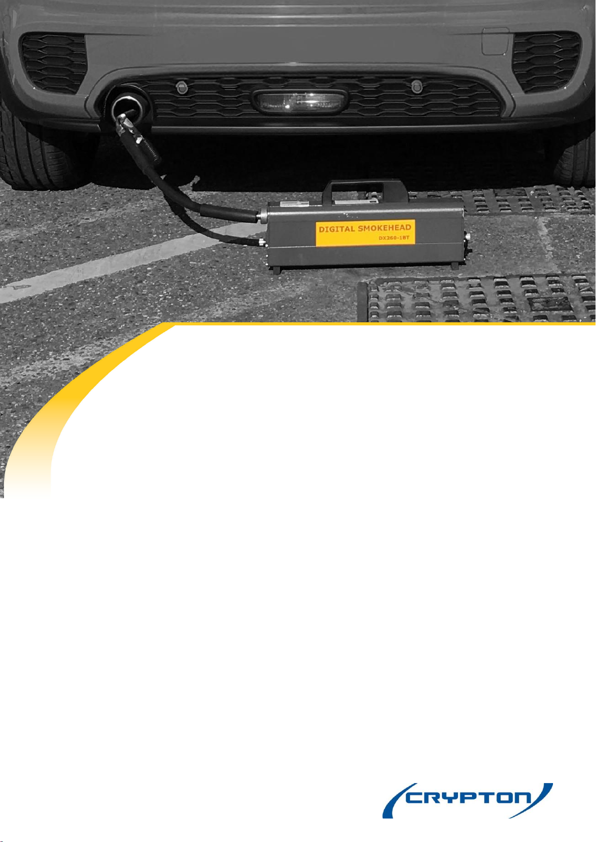
UK DX260 Smokemeter
EQUIPMENT MANUAL
I323805 Issue 1
Crypton - a Brand of the Continental Corporation
Page 2

2
Contents
Introduction
Health and Safety .................................................................................. 4
Smokehead ............................................................................................. 5
Installation ...................................................................................................................................... 6
Operation ........................................................................................................................................6
Battery Charging (Wireless only) ............................................................................................... 10
Maintenance ................................................................................................................................. 11
Oil Temperature Probe ........................................................................ 15
Adapters ......................................................................................................................................... 15
Connection ..................................................................................................................................... 15
Operation ....................................................................................................................................... 15
Engine Tachometers ............................................................................ 16
Connection ..................................................................................................................................... 17
Battery - CDSS6/DX211-12 ........................................................................................................ 17
Consumables ......................................................................................... 18
Technical Specifications ..................................................................... 20
After Sales and Support ...................................................................... 23
UK Customers ............................................................................................................................... 23
Overseas Customers .................................................................................................................... 23
Disposal of equipment .................................................................................................................. 23
Disposal of batteries ..................................................................................................................... 23
Page 3

3
Important Information
Important
Every reasonable effort has been made to ensure that information within these Operating Instructions
is correct at the time of release, but Continental Automotive cannot accept responsibility for any
errors that may occur.
The information in these Operating Instructions is subject to change without notice, and does not
represent a commitment on the part of Continental Automotive.
Service & Warranty
The reliability of this equipment is fully supported by our service agents, with repair workshops and
field service engineers to provide a full range of After-Sales Care, including installation, contract
maintenance, factory overhaul and emergency repairs on site. Please refer to the page at the end of
this manual for full details.
Note: If a service engineer is called out under service warranty where, upon inspection and test the
equipment is found to be in full working order and no fault found, the user is liable to be charged the
cost incurred for this call out. Before calling out an engineer, ensure your equipment is faulty by
checking its operation, particularly mains supply and fault codes/self test if applicable.
Software Licence
Further to our general Terms & Conditions of Sale, the software described in these Operating
Instructions is furnished under the following Software Licence Agreement:
1.
Licence: You may use the program on the machine provided. You may not copy, duplicate
or transmit the program in any form, in whole or in part, without the express prior written
permission of Continental Automotive.
2.
Term: The licence is effective until terminated. You may terminate the licence by destroying
the program together with all copies, or returning the program to Continental Automotive.
3.
Continental Automotive does not warrant that the program will meet your requirements
or that its operation will be uninterrupted or error free.
4.
In no event will Continental Automotive be liable to you for any incidental or consequential
damages, including lost profits, business operation and the like, arising out of the use or
inability to use this program.
You acknowledge that you have read this Agreement, understand it, and agree to be bound by its
provisions.
WARNING: Do not attempt to operate this equipment unless you have read and understood
these instructions.
WINDOWS® is a registered trademark of Microsoft® Corporation
Page 4

4
Health And Safety
1.
The equipment is not weatherproof and should not be used outside in rain or snow.
2.
The internal circuits and components of the analyser should not be tampered with. No
internal parts are operator serviceable.
3.
Operators should exercise due caution with regard to the engine fan and associated belts.
4.
Always provide ventilation by using an exhaust gas extraction system or by having an
adequate supply of fresh air.
5.
Before starting an engine, ensure that the gear selector is in neutral or park.
6.
Care should be taken with regard to scalding from the cooling system, burns from the
exhaust system and electric shocks from the ignition HT system.
7.
When disconnecting the fuel system of a hot engine beware of the fire hazard caused by
fuel spilling onto manifolds, ignition distributor, etc.
8.
Position the mains cable and sample pipe in such a manner that they do not present a
hazard to anyone.
9.
The earth lead of the mains supply cable MUST ALWAYS be connected to a good earth
point.
10.
Operators should not allow themselves to come into contact with water or other similar
conductors when using the equipment.
11.
Equipment should be sited in an area designated and clearly marked:
FOR USE BY AUTHORISED PERSONNEL ONLY
Vehicle emissions are dangerous. In particular, Carbon Monoxide (CO) from
a vehicle exhaust is a highly poisonous gas. If breathed in, it is absorbed by the
blood and will result in greatly slowed reactions and if absorbed in
sufficient quantity can be fatal. Published figures show that a
concentration of 0.3% CO in the air can be fatal if inhaled for 30 minutes.
Page 5
5
Installing Equipment
A number of optional devices may be fitted for use with the Smoke Test. Please refer to the
operating instructions for details of usage.
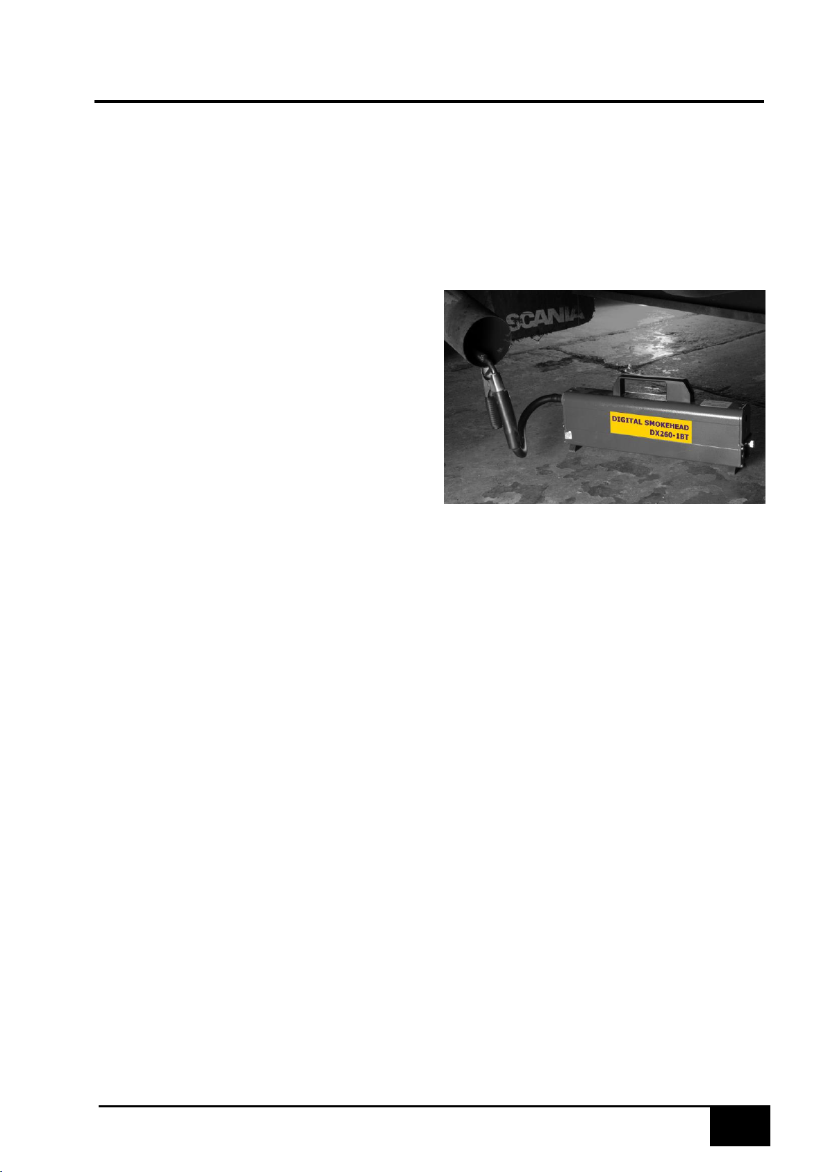
DX260-1xx SMOKEHEAD (Cabled)
The DX260-1 Smokehead is plugged in to a connector positioned on its cradle base. The base
is then connected to the host equipment. The appropriate Sampling Pipe is then connected to
the Smokehead.
The Smokehead should be returned to base
when not being used.
DX260-1xxBT SMOKEHEAD (Wireless)
The DX260-1BT wireless Smokehead uses wireless technology to communicate directly with the
host computer. The Smokehead has rechargeable batteries built in to enable approximately 1.5
hours of continuous use between charges.
The Smokehead should be returned to its charger between tests to keep the batteries charged. The
Smokehead will go into hibernation mode if it is not being communicated to by the computer whilst it
is off the charger base for longer than approximately 6 minutes.
Page 6
6
Sampling Pipes
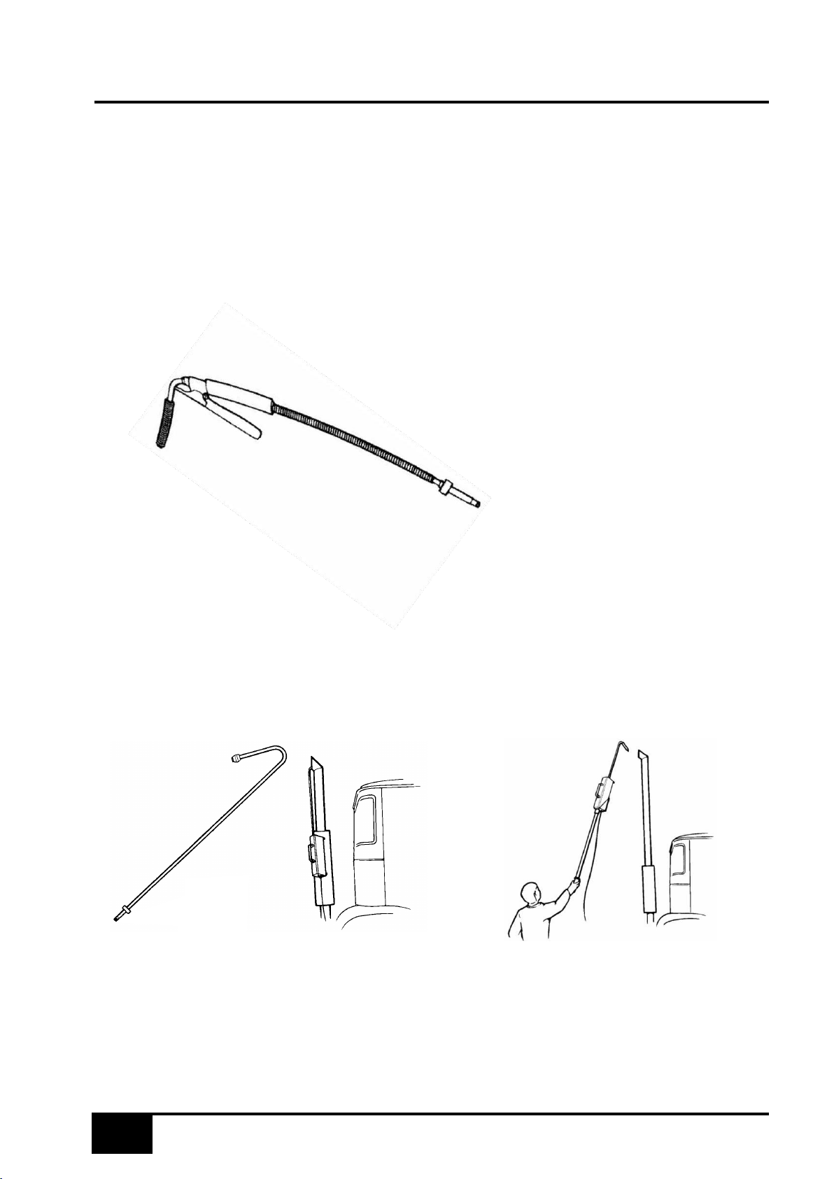
Connect the appropriate sampling pipe to the sampling head.
Sampling pipe DX210-4A
The sampling pipe DX210-4A can be used for all vehicles, but for convenience of
use alternative pipes are available.
DX210-4A
Sampling pipe DX210-6
Sampling pipe DX210-6 is used for vertical exhausts. Hang the sampling pipe and the
sampling head as shown in the illustration. For very high exhausts, an extension pole 1.5 m or
2 m length may be fitted to the sampling head using an extension kit DX260-160L (1.5m) or
DX260-160H (2.0m) as illustrated.
DX210-6
Page 7
7
Sampling Pipes
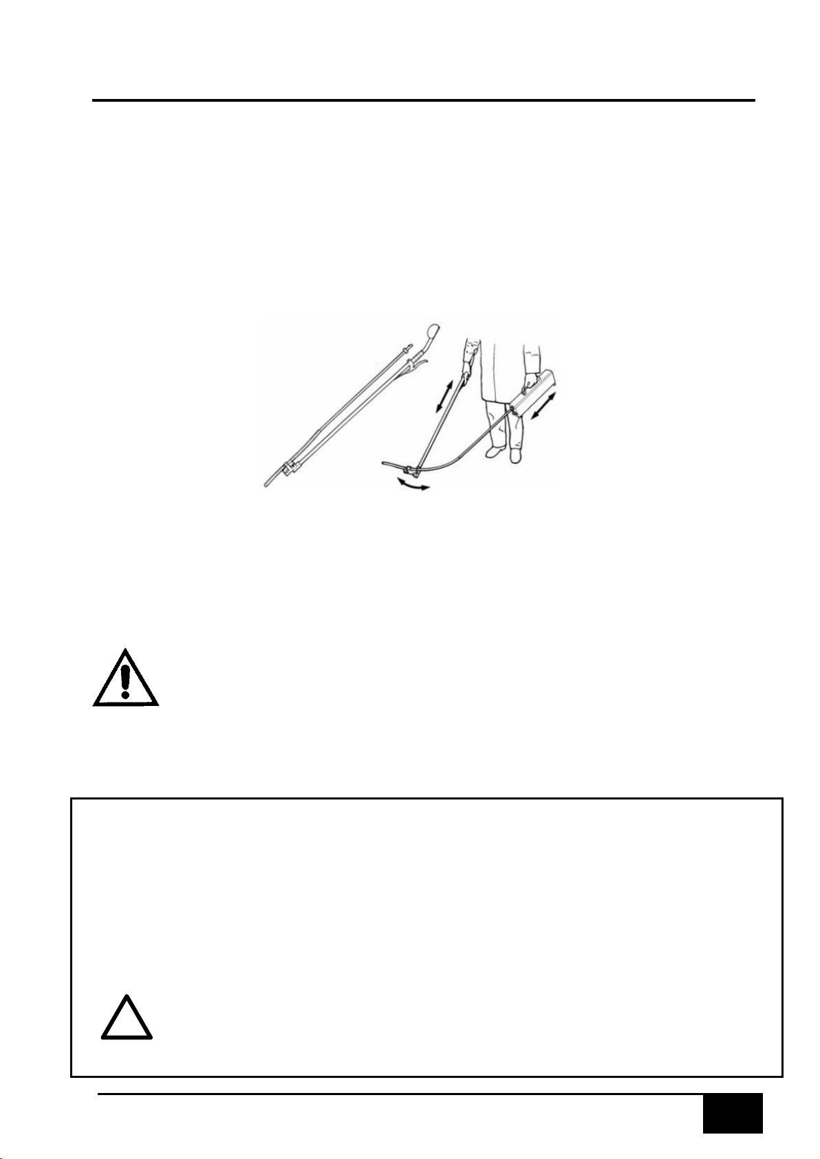
Sampling pipe DX210-5C
The sampling pipe DX210-5C has remote control and is used to access mid-chassis exhausts
on large commercial vehicles. To use, hold the sampling pipe and the sampling head as shown
in the illustration with the arm rest under the forearm. The head of the pipe has a pivoting action
so that the 'aim' of the pipe can be changed by moving one arm forwards or backwards relative
to the other arm.
Use the hand lever to operate the jaws and clamp the pipe in position, then allow the remote
control and the sampling head to rest on the floor.
NOTE:
CAUTION:
WARNING:
Before fitment of a sampling pipe, inspect its 'O' ring for damage and renew if
necessary (order part number DX210-5/60).
Periodically apply a smear of grease to the 'O' ring to assist fitment of the
sampling pipe to the sampling head.
The results of free acceleration testing will be affected by changes in
sampling pipe diameter and/or length. Only genuine pipes must be used and
their design must not be altered in any way.
The smokehead body must always be positioned in clean air and away from
exhaust fumes when in use.
Sampling pipes can get very hot; take care when disconnecting from the
sampling pipe.
USING THE SMOKEHEAD OUTSIDE
If it is necessary or desirable to test a vehicle outside the workshop, the following points must
be borne in mind.
The sampling head is weather resistant and may be used in temperatures down to a minimum
of -15ºC. But in the case of severe weather and heavy rain – DO NOT USE OUTSIDE!
WARNING:
!
The power supply and PC are not weather protected and for the safety
of both the operator and the equipment, these parts MUST be kept
under cover in inclement weather conditions.
Page 8
8
Operation
WARMING-UP
Switch on power to the base unit. The ‘Power On’ light will illuminate.
There is a warm-up time of 5 to 15 minutes dependent on the outside temperature. During
this time the Smokemeter will not function.
NOTE:
For details of software controlled procedures, refer to the appropriate software
manual.
WIRELESS SMOKEHEAD OPERATION (DX260-1BT)
For wireless systems the operation of the equipment is identical to the cabled
systems but a wireless Smokehead (DX260-1BT) is utilised.
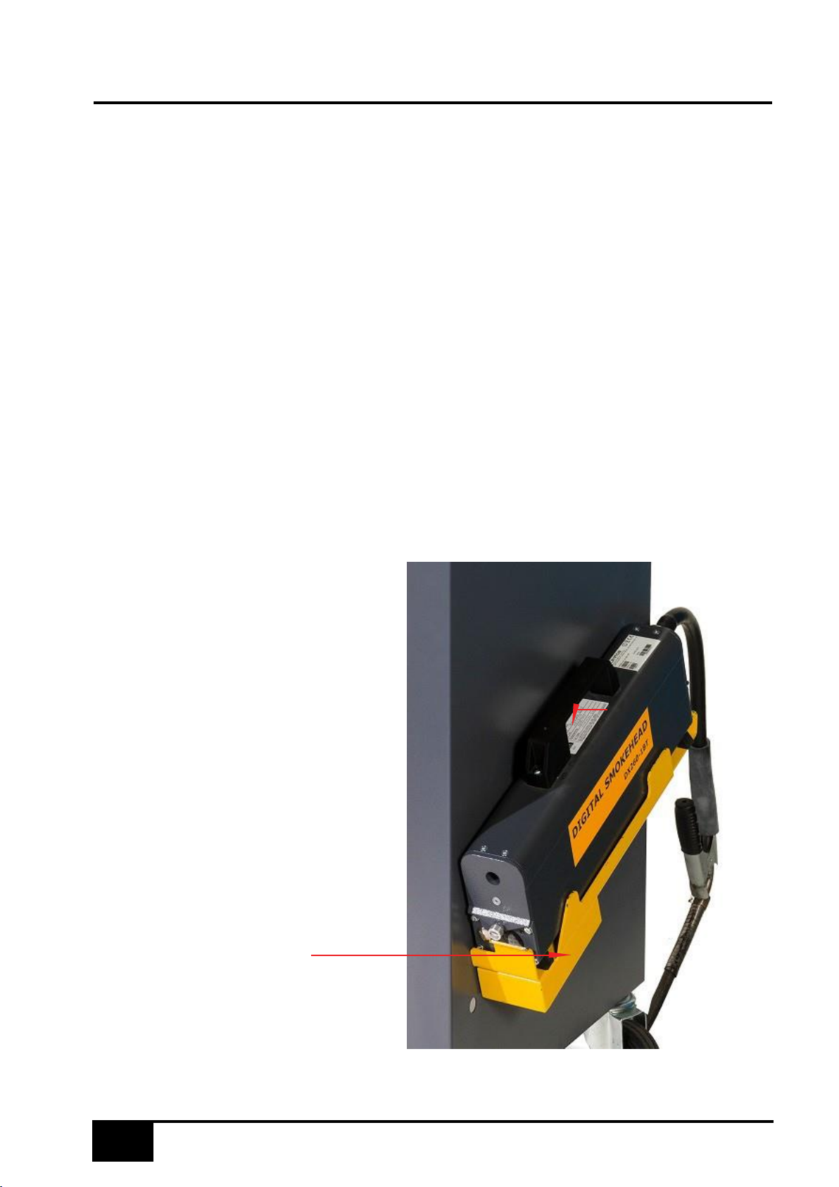
When the equipment is first
switched on the smokehead
should be firmly positioned onto its
charging cradle and the unit should
be allowed to charge for a
minimum of five to six hours (or
preferably left overnight) to fully
charge the batteries.
The equipment screen will prompt
the user to return the smokehead to
its charging cradle between tests.
This must be obeyed in order to
proceed further. Failure to return the
smokehead to its base will result in
a depletion of the battery charge.
The test will not continue until the
smokehead has been returned.
Blue flashing LED indicates
battery charging operation
Ensure the Smokehead
is firmly positioned on its
charger base
Page 9

9
Battery Charging
Care, Modes & Endurance:
The DX260-1BT wireless Smokehead contains a Multi-Cell Rechargeable Battery designed to give
a maximum of 1.5 hours endurance from a full charge.
The Smokehead must always be replaced on the charging cradle in between tests.
To recharge, the Smokehead must be returned to and correctly located on its charging cradle. This
will maximise the battery endurance and is also necessary for test results to be printed.
On the handle of the Smokehead is a highly visible Blue Light emitting Diode (LED). This LED gives
indication of the status of the Smokehead whether or not it is on its charging Cradle.
The nominal endurance of the internal Battery pack is 1.5 hours continuous use from a full charge
and cold start. This will vary according to ambient temperature. For optimum use and battery life,
the smokehead should be removed from the charging cradle for the minimum amount of time and
returned to the charger immediately after testing or as prompted by the smoke test Software.
The rate of charging is dependant on a combination of Battery Voltage and Battery Temperature. If
the Smokehead has seen reasonable use the charger will switch to ‘Fast Charge’, taking
approximately 1.5 hours to fully recharge. Once full terminal Voltage has been reached, the battery
charging rate is reduced to ‘Trickle Charge’. When charging for a protracted period, for example
overnight, a trickle charge of 15 hours will completely recharge the internal battery. A blue LED on
the Handle indicates the Charging Status.
It is strongly advised that the Charger Cradle be left permanently switched ON with the Smokehead
in situ overnight to ensure full operational usage at beginning of the working day.
It is also strongly recommended that the batteries be completely discharged on a monthly
basis by setting the program to Live Readings with the smokehead off the charger. This could
be done at the end of the working day.
Please note that rechargeable batteries have a finite lifespan, therefore the battery pack will need
to be replaced periodically if the smokehead is no longer sustaining sufficient charge for
correct operation. Please contact a Product Support for battery replacement information.
LED Indication
1. Smokehead removed from Charging Cradle:
LED ‘On’ continuously: Smokehead is running on internal Battery.
LED pulsing ‘ON’ for 2 seconds, ‘OFF’ for 0.5 seconds: Smokehead battery has reached a Low
Voltage condition, and has less than 10 minutes life left before Auto-shutdown.
LED ‘OFF’: Low Voltage condition. Smokehead will Auto Shut down. No more testing possible until
Smokehead battery has been recharged.
If the Smokehead has received no Communication from Host Computer for over 6 minutes it will go
into ‘Sleep’ Mode. Return the Smokehead to the Charging Unit to invoke a response.
Page 10

10
Battery Charging
To recover from ‘Sleep’ mode, the Smokehead should be put back in its Charging Cradle, and the
LED function observed.
2. Smokehead returned to Charging Cradle:
FAST CHARGE (2.5 flashes per second):
The Smokehead is in ‘Fast Charge’ Mode. The battery should fully charge within 1.5 hours.
TOP-UP CHARGE (1 flash per second):
The Fast Charge cycle has completed and the battery is being brought to full charge.
SLOW CHARGE (1 flash every 2 seconds):
The Smokehead battery is in ‘Slow Charge’ mode, the charging rate determined by either
Terminal Voltage or, Battery Cell temperature.
TRICKLE CHARGE (1 flash every 3 seconds):
LED Flashing ON/OFF shows the Smokehead battery is in ‘Trickle-Charge’ mode indicating that
the batteries are fully charged.
Fault Diagnosis:
FAST FLICKER (8 flashes per second or more):
The smokehead has detected poor charging contacts. Clean the contacts on both the cradle and
the smokehead feet and replace on charger.
LED NOT ILLUMINATED:
Return the Smokehead to Charging Cradle. LED should display according to Charging level
required.
LED NOT ILLUMINATED WHEN SMOKEHEAD IS ON CHARGING CRADLE:
Check that the Smokehead is correctly seated on the charging Cradle. The Smokehead has twin
connectors on each insulated foot, and may be connected either way round.
Check the Charging Cradle is connected to the 240 V AC Mains.
Check that the sprung connectors that transmit the Charging Current on the Charging Cradle are
clean and not stuck in a depressed condition.
Check that the Charging Connectors on the insulated mounts on underside of the Smokehead are
clean and free of dirt and obstructions.
To check the charging Voltage at the Charging Cradle: Connect a Digital Multimeter set to
measure up to 30V DC to the two charging Connectors on the charging Cradle, and depress the
Central Charging Switch. A Voltage of 28 V to 30 V DC should register on the Multimeter Display.
The internal battery pack has a finite lifespan and will need to be replaced periodically. This should
be carried out by a qualified Service Engineer.
There are no user serviceable parts in the Smokehead.
Page 11
11
Maintenance Of The Smokehead
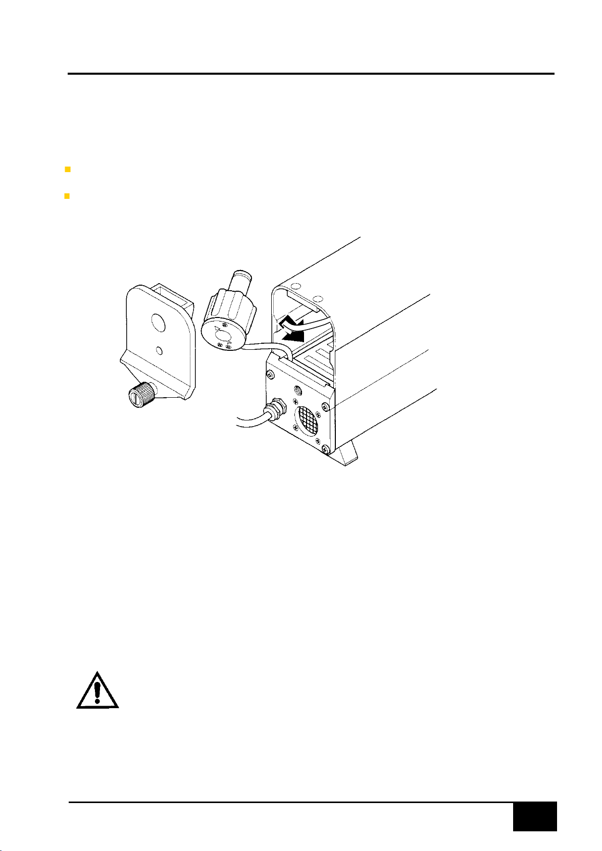
Serial numbers
Serial number locations are as follows:
•
Smokehead internal - Underneath the lens housing (remove end
cap for access).
•
Smokehead external – on underside of Smokehead.
Checking the Smokehead serial number
CLEANING SAMPLING PIPES
Under normal circumstances the sampling head does not require cleaning. If a sampling pipe
becomes restricted with deposits, the test results can be affected.
To clean a sampling pipe, remove the sample probe from the smokehead. Blow through the
sample pipe only, using compressed air. DO NOT BLOW THROUGH THE SMOKEHEAD.
WARNING:
Wear eye protection and provide a suitable container to catch the
soot that will be blown out from Sample Pipe. DO NOT use
compressed air on the Smokehead body.
Page 12
12
Lens Cleaning
Two lenses are fitted in the smokehead, one at either end.
The Smokemeter checks the cleanliness of the lenses at the start of each test, and the PC
will provide a warning when cleaning is required.
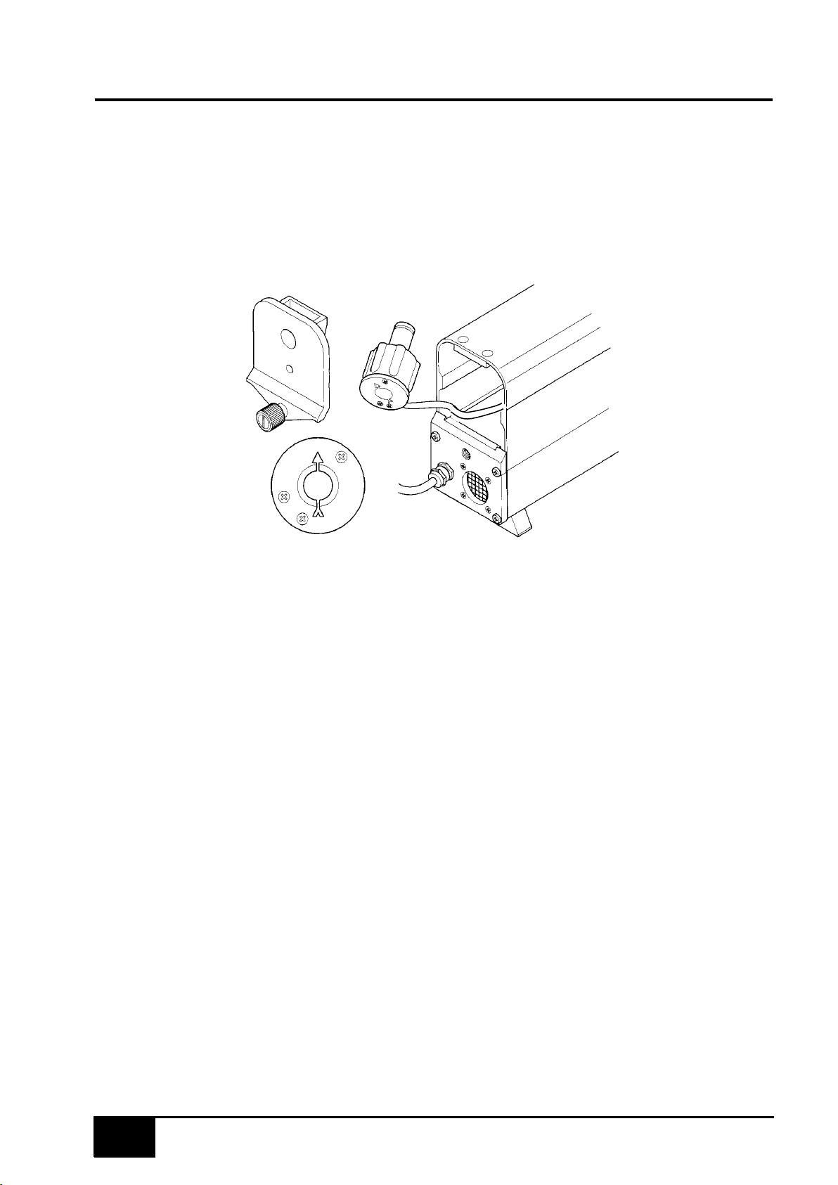
Note orientation of lens housing
(arrow up)
Accessing a lens
The cleaning procedure is as follows.
1.
If fitted, remove the sampling pipe.
2.
Unscrew the knurled knob at the sampling pipe end of the sampling head and remove the
end cap.
3.
Carefully pull out the lens housing and wipe the lens with a soft cloth (if required, a little
methylated spirit will assist cleaning).
4.
Refit the lens housing with the arrow pointing upwards (a little silicon grease on the 'O'
ring will assist fitment –but do not get on lens!).
5.
Refit the end cap and tighten the knurled knob.
NOTE: Ensure the end cap locates fully against the body of the sampling head before
tightening the knob. If not correctly located, the lens housing is probably not
fully home.
6. Clean the lens at the other end of the smokehead in the same way.
NOTE: The end cap for the sampling pipe must be fitted at the end away from the sampling
head cable.
Page 13
13
Smokehead Cable And Fan Renewal
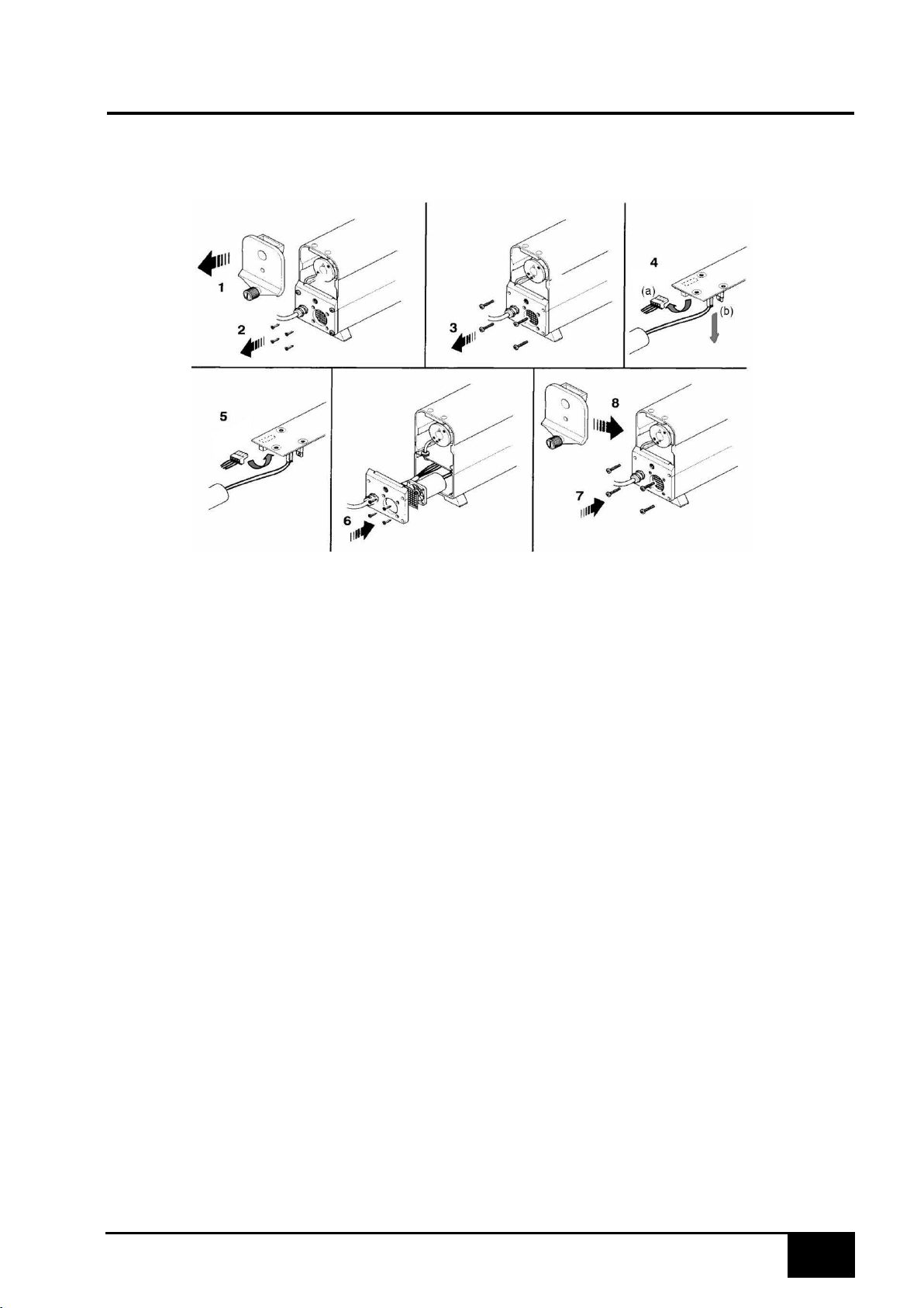
Should the cable become damaged and require renewal, the procedure is as follows.
1.
Unscrew the knurled knob (1) and remove the end cap.
2.
Remove the four countersunk screws (2) which secure the internal fan and grille to the
smokehead end plate.
3.
Remove the four panhead screws (3) securing the end plate and carefully ease the plate
clear of the housing.
4.
Disconnect the 4-pin multiplug (4a). If carrying out a fan replacement disconnect the 2-pin
plug (4b) and replace the fan. Carefully fit the fan and fan grille to the end plate (4
countersunk screws).
5.
Remove the 4 wires from the 4-way plug. Undo the metal cable clamp from the end plate.
Loosen the cable gland strain relief and remove the cable from the end plate.
6.
Re-fit the new cable through the cable gland strain relief and secure to the end plate with the
metal clamp (Important: secure the clamp on the earth braid of the cable). Re-fit the 4-way
plug. Ensure the cable gland strain relief is tightened.
7.
Connect the 4-pin multiplug (4a) and the 2-pin plug (4b).
8.
Locate the end plate to the smokehead (cable on left hand side) and loosely secure with the
four panhead screws.
9.
Check that the lens housing is fully in, then fit the end cap and secure with the knurled knob.
Fully tighten the knurled knob then slacken half a turn.
10.
Push the end plate upwards as far as it will go, and then fully tighten the 4 panhead screws.
11.
Fully tighten the knurled knob on the end cap.
Page 14
14
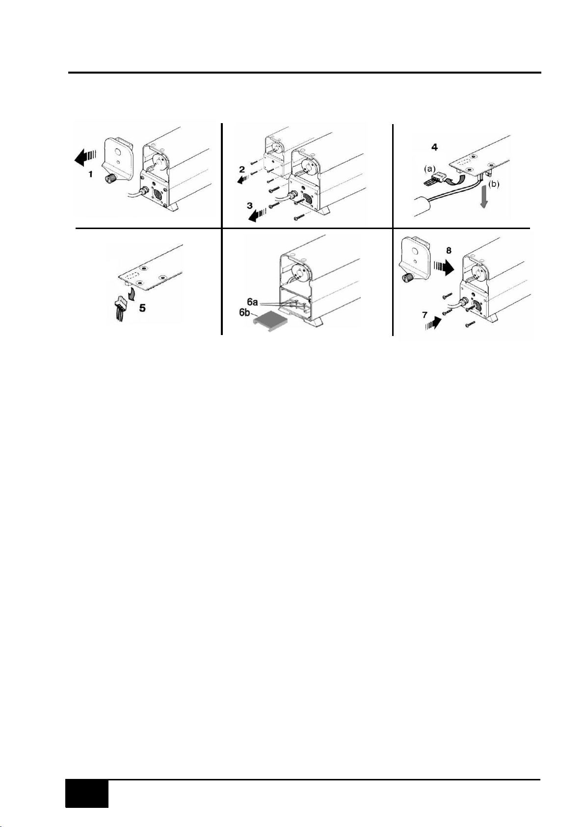
Smokehead Battery Replacement
(DX260-1BT ONLY)
Should the battery pack require renewal, the procedure is as follows.
1.
Unscrew the knurled knob (1) and open up both end caps.
2.
Remove the four panhead screws (2) & (3) securing the end plates and carefully ease the
plates clear of the housing.
3.
At the fan end, disconnect the 2-pin plug (4a) and also the 2-pin plug (4b) connected to the
fan.
4.
At the probe end, disconnect the 3-pin plug (5).
5.
Depending on which version - loosen the two screws (6a) or the plastic spacer (6b) securing
the battery pack and remove old battery pack, do not remove by pulling the cables. Ensure
the connectors do not foul any components during removal/replacement of the board.
6.
Replace with new battery pack (note orientation). Discard the two securing screws
(earlier versions) or the plastic spacer (later versions)– no longer required.
7.
Re-connect the 2-pin plug (4a), the 2-pin plug (4b). and the 3-pin plug (5).
8.
Relocate the end plates to the smokehead and loosely secure with 4 panhead screws (7).
9.
Check that the lens housing is fully in, then fit the end caps and secure with the knurled
knob. Fully tighten the knurled knob then slacken half a turn (8).
10.
Push the end plate upwards as far as it will go, and then fully tighten the 4 panhead screws.
11.
Fully tighten the knurled knob on the end caps.
NOTE: Ensure the battery is disposed of in accordance with current rules and regulations
applicable and enforced in your area. When the equipment is first switched on the Smokehead
should be firmly positioned onto its charging base and the unit should be allowed to charge for a
minimum of five to six hours (or preferably left overnight) to fully charge the batteries.
Page 15
15
Oil Temperature Probes
ADAPTERS
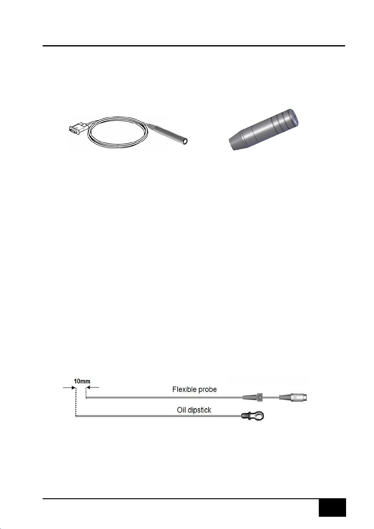
The DX211-11 and DX211-11BT Temperature Probe Adapters are used in conjunction with the
DX210-25A or DX210-26 oil probes for engine temperature measurements. The DX211-11 is
hard-wired to the smokemeter; the DX211-11BT communicates via wireless technology.
DX211-11
Cabled Temperature Probe Adapter
DX211-11BT
Wireless Temperature Probe Adapter
Connection to the Smokemeter
The DX211-11 utilises an RS232 communications cable for connection to the Smokemeter. The
unit connects to the smokemeter via a serial port. When not in use the flexible probe should be
stored in a protective holster
The DX211-11BT is a wireless device that will communicate with a wireless enabled
Smokemeter. A charging holster is supplied which should be used to store and charge the unit
when not in use. The DX211-11BT batteries will be charging at all times whilst stored in the
holster, indicated by the status indication light on the probe adapter glowing red.
Temperature probes
There are two flexible temperature probes, either of which can be plugged into either adapter. The
DX210-26 is a standard 0.75M probe, the DX210-25A is a 2.5M long-reach probe.
Connect the flexible oil probe to the socket of the DX211-11 or DX211-11BT. This connector
includes a snap-lock feature that ensures a reliable connection between the two devices.
Adjusting oil temperature probe length
Before testing, the probe must be adjusted to the correct length as follows:
Lay it alongside the vehicle dipstick (see illustration) and adjust the position of the depth stop
until the effective length of the probe is approximately 10mm shorter than the dipstick.
WARNING: ENSURE THAT THE OIL TEMPERATURE PROBE IS SET TO THE CORRECT
DIPSTICK LENGTH AND THAT IT IS CLEAN FROM DEBRIS BEFORE INSERTING INTO THE
ENGINE. FAILURE TO DO SO MAY RESULT IN SERIOUS DAMAGE TO THE PROBE AND/
OR ENGINE.
DX210-26 / DX210-25A
Page 16
16
Engine Tachometers
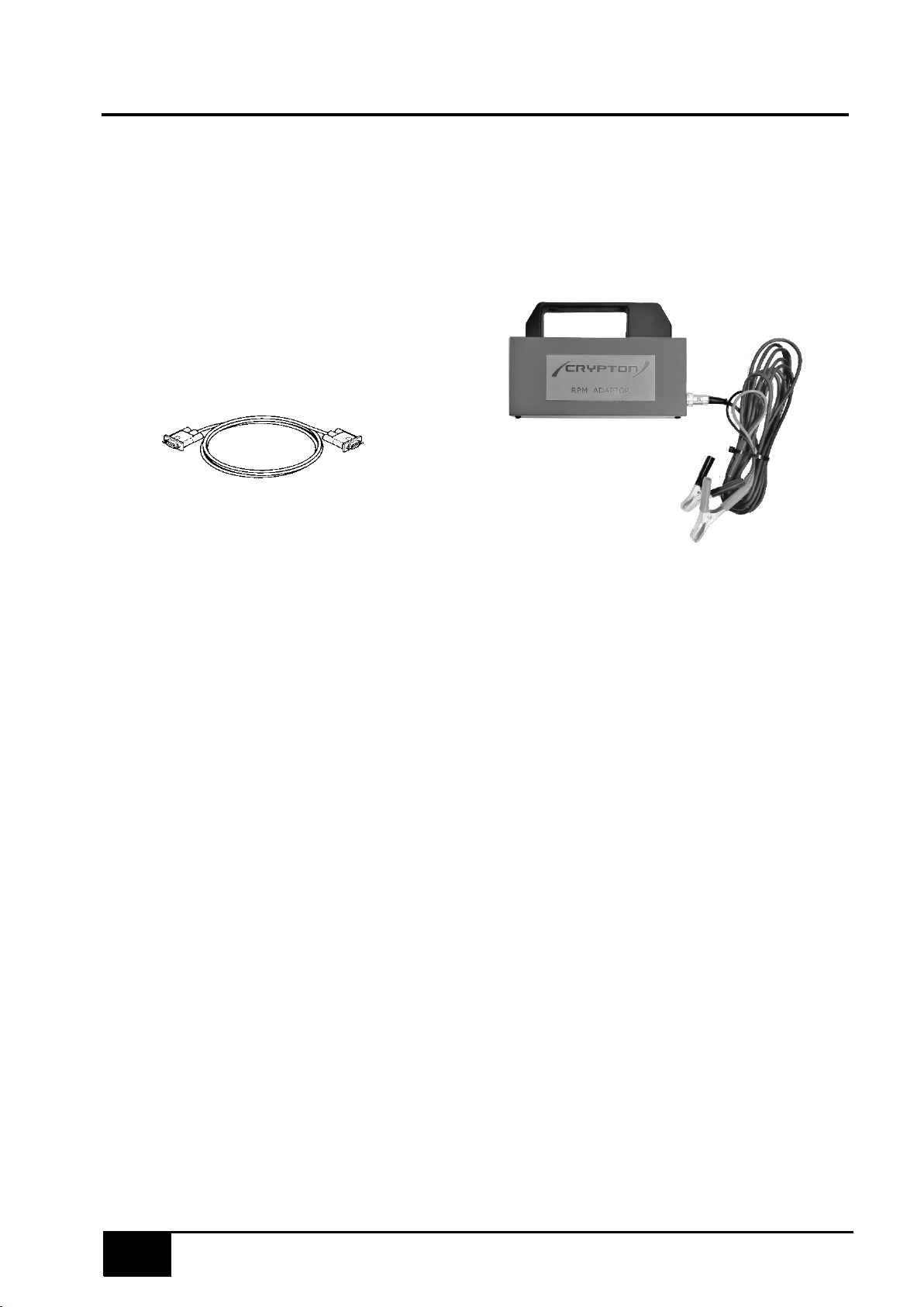
RPM TACHO - Battery CDSS6 (DX211-12)
The CDSS6 RPM Tacho provides a signal via an RS232 comms lead DX230-261. The comms
lead is connected directly to the host equipment. The CDSS6 derives its power from the
vehicle battery.
DX230-261
(RS232 cable)
RPM TACHO – Battery Wireless CDSS6BT (DX211-12BT)
The CDSS6BT RPM Tacho is identical to the CDSS6 except that it provides a signal to the host
PC via a wireless connection. It will only work with wireless enabled equipment and does not use
the DX230-261 comms lead. The CDSS6BT derives its power from the vehicle battery.
USING THE ENGINE TACHOMETERS
Ensure the vehicle engine is switched off before connecting engine speed adapters to the vehicle.
The following types of engine speed adapter are available:
CDSS6/CDSS6BT
(DX211-12/DX211-12BT)
Page 17
17
Engine Tachometers
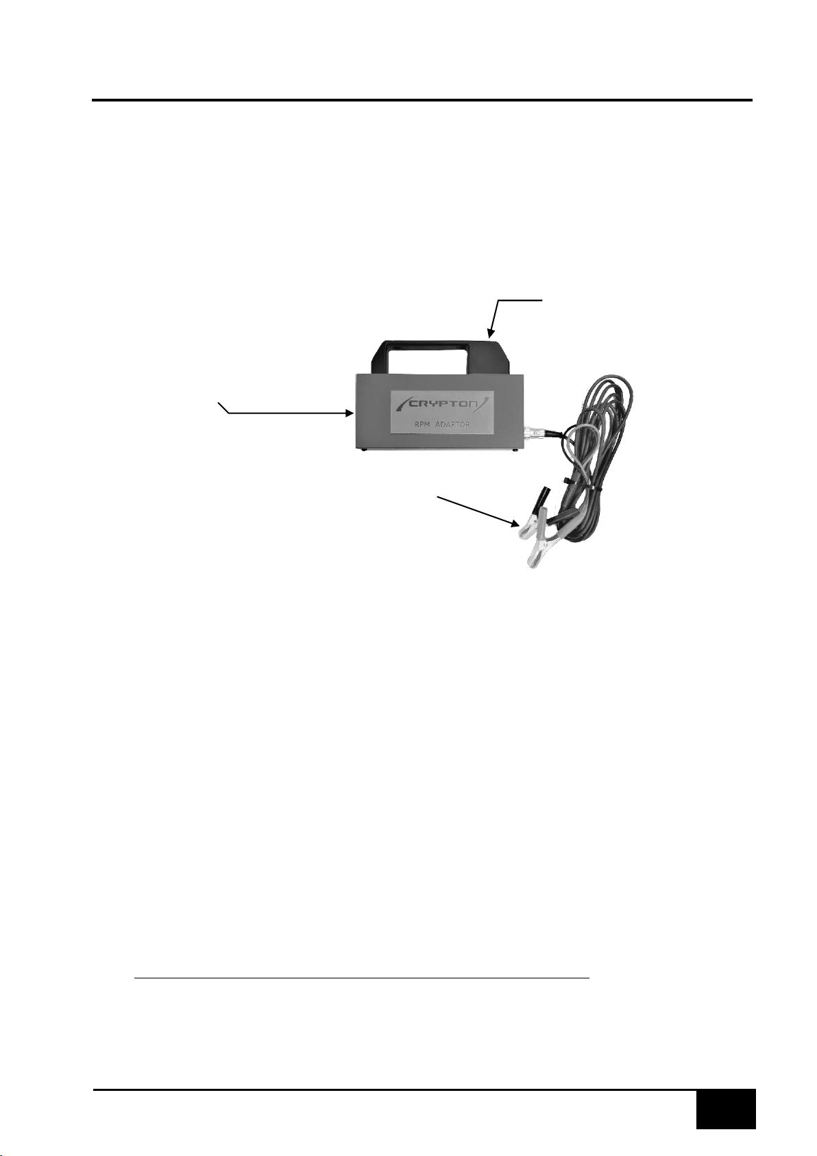
BATTERY TACHO CDSS6,CDSS6BT (DX211-12, DX211-12BT)
Battery sensing type for Petrol and Diesel Engines
This adapter measures the frequency modulation ripple of the alternator across the battery
terminals, and converts this information into engine speed signal.CDSS6BT and DX211-12BT are
wireless variants
Connections
STATUS LED
ON: Power/Initialising FLASH:
Measurement in progress
SIGNAL OUTPUT
via comms lead DX230-261 (Not
CDSS6BT)
BATTERY CLIPS Red to
battery +VE Black to
battery -VE
CDSS6/CDSS6BT RPM Operation
Ensure the CDSS6 is connected to the host PC via the DX230-261 Comms lead (Not required on
CDSS6BT).
Before starting the vehicle, attach the crocodile clips on CDSS6 power/sensing cable to battery
terminals, ensuring that the polarity is correct.
Start engine, switch on vehicle lights and allow to idle.
The unit will search for a steady speed each time it is powered up, if the engine speed falls or the
engine type is changed. This is the initialisation period and may last up to 17 seconds. During this
time, the status LED will flash slowly and the rpm will read zero.
Once the speed has been detected, readings will appear on the host analyser. The CDSS6
updates 10 readings per second.
Note: Please note that on a small number of vehicles the readings may be unstable, inaccurate or
unreadable. To minimise the risk of this:Load the battery as much as possible by doing the
following: Switch on the vehicle headlights/Main beam/
Fog/Spots,
Switch on the heated rear window,
However - Switch off the cabin fan as this can introduce interference.
Keep the engine speed stable during the initialisation time <17Sec.
If, after initialisation the speed is stable but reading incorrectly, change the
cylinder setting on the ‘Tacho Set-up’ screen until the correct value appears.
Page 18
18
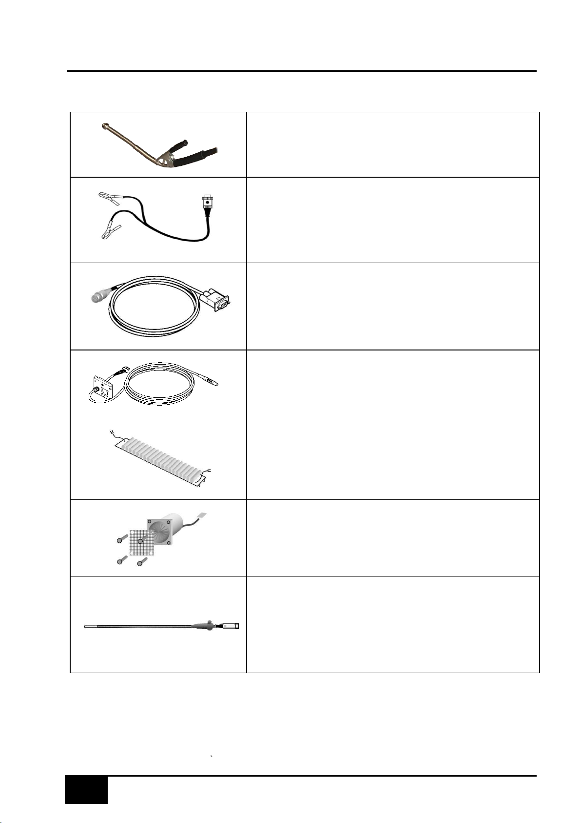
Consumables
Sampling pipe (Standard)
DX210-4A - A2C88171800
Battery Tacho Power/Sensing cable
CABL3016 -CDSS6 to vehicle battery A2C87921500
Tacho Communications Cable
DX230-261 - 2m Standard (for CDSS6)
Cable – Smokehead Cable Assembly
DAS00497 - 10m Standard A2C89476700
DX260-1BT/01 Battery Pack (For use with DX260-1BT Head only)
- A2C88489000
DX230-130/16 Fan Kit (Replacement fan for DX260-1 & DX260-1BT)
- A2C88247300
Oil Temperature Probes
DX210-25A
- 2.5m (Use with DX211-11 or DX211-11BT)
A2C89424100
DX210-26
- 0.75m (Use with DX211-11 or DX211-11BT)
A2C89335700
Page 19
19
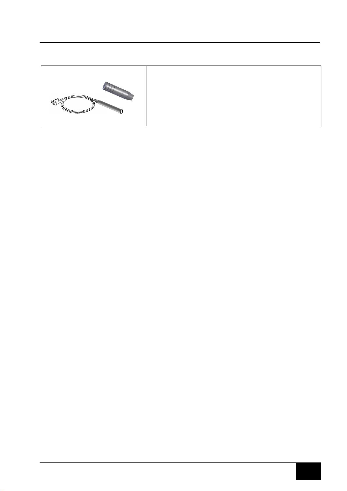
Consumables
Temperature Probe Adapters (use with DX210-25A
and DX210-26 probes)
DX211-11
DX211-11BT
- 5m cabled Adapter A2C88694100
-
Wireless Probe Adapter
A2C89185500
Page 20
Technical Specification
20
Page 21
Technical Specification
21
Page 22
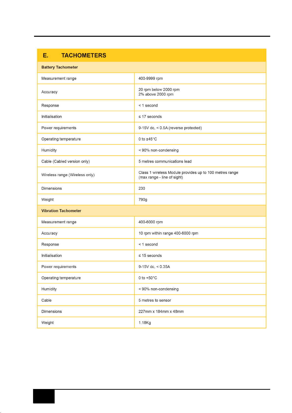
Technical Specification
22
Page 23
After Sales Service
Apart from the routine maintenance and adjustments stipulated in this manual the equipment must
not be tampered with in any way. All further servicing must be carried out only by an engineer
from our Authorised Agents. Failure to observe these conditions will invalidate the Guarantee.
UK Customers
If you require a Service Engineer to attend ON SITE within the UK, for any of the following
reasons:
▪ An equipment fault,
▪ For machine calibration,
▪ You need spare parts,
▪ Equipment covered by this manual requires returning for factory overhaul.
Please contact our Product Support Helpline at the following number:
Tel: 0121 725 1400
e-m
ail: [email protected]
Crypton can provide information and contracts covering the following: Software Support Contracts;
Software Updates & Accessories.
Overseas Customers
Service and spare parts cover outside the UK is provided by the agent from whom your equipment
was purchased.
Disposal of equipment
• Do not dispose of this equipment as miscellaneous solid municipal waste but
arrange to have it collected separately.
• The re-use or correct recycling of electronic equipment (EEE) is important in
order to protect the environment and the wellbeing of humans.
• In accordance with European Directive WEEE 2002/96/EC, special collection points are
available for the delivery of waste electrical and electronic equipment.
• The public administration and producers of electrical and electronic equipment are involved in
facilitating the processes of the re-use and recovery of waste electrical and electronic
equipment through the organisation of collection activities and the use of appropriate planning
arrangements.
Unauthorised disposal of waste electrical and electronic equipment is punishable by law with
appropriate penalties.
Disposal of batteries
•
Batteries must be recycled or disposed of properly.
•
Do not throw batteries away as part of normal refuse disposal.
•
Do not throw batteries into open flame.
23
Page 24

CR2182 MY18
Continental Automotive Trading UK Ltd | 36 Gravelly Industrial Park | Birmingham | B24 8TA | United Kingdom
Tel: +44 (0) 121 725 1400 | Email: [email protected] | www.cryptontechnology.com |
Crypton - A Brand of the Continental Corporation
With all the quality, service and backup you would expect from a UK company with a long standing history like
Crypton.
ATL is an integrated product that can be purchased as either a complete test lane or as separate components
making it an ideal choice whether up grading for One Man testing or a completely new Automated Test Lane.
ATL can be added to the majority of Crypton’s existing emission products.
ATL can be purchased using Crypton Finance to assist with financial planning and cash flow.
E & O E. The Company reserves the right to introduce improvements in design or specification without prior notice.
The sale of this product is subject to our standard terms, conditions and relevant product warranty
 Loading...