

Page 1

OPERATING INSTRUCTIONS
TES1489/A
Dec 2005
BRAKE TESTER 660-R
Page 2

660-R OPERATING INSTRUCTIONS Page 2
IMPORTANT
Every reasonable effort has been made to ensure that information within
these Operating Instructions is correct at the time of release, but Crypton
cannot accept-responsibility for any errors that may occur.
The information in these Operating Instructions is subject to change
without notice, and does not represent a commitment on the part of
Crypton.
Service & Warranty
The reliability of this equipment is fully supported by our service agent.
Please refer to the page at the end of this manual for full details.
Note:
Your attention is drawn to our Terms & Conditions of Sale. If a service
engineer is called out. under service warranty where, upon inspection and
test the equipment is found to be in full working order and no fault found,
the user is liable to be charged the cost incurred for this call out. Before
calling out an engineer, ensure your equipment is faulty by checking its
operation, particularly mains supply and fault codes/self test if applicable.
WARNING:
Do not attempt to operate this equipment unless you have read
and understood these
instructions.
Page 3

660-R OPERATING INSTRUCTIONS Page 3
CONTENTS
Safety precautions 4
Hints and Tips 5
INTRODUCTION 6
Description of system components 6
Emergency switch 6
Pit unit 6
Control unit 8
Motor control 8
Alternative display 8
Printer 8
Remote control 9
Guide to testing 11
Test description 12
MOT Test Procedure – Class IV 12
Enter car on PC 12
Reset system 12
Front Axle 12
Centre 12
Left brake test 12
Right brake test 12
Bind, ovality and imbalance test 12
Rear Axle 13
Centre 13
Left brake test 13
Right brake test 13
Bind, ovality and imbalance test 13
Parking Brake 14
Left brake test 14
Right brake test 14
Printing results 14
Manual Testing 15
Class IV 15
Class III - Testing one wheel only 16
Prompt sheet 17
Calculations 18
Maintenance 19
Technical Specification 21
After Sales Service 22
Notes 23
Page 4

660-R OPERATING INSTRUCTIONS Page 4
SAFETY PRECAUTIONS
Read these operating instructions carefully and thoroughly before
attempting to operate the equipment.
This operating manual should be available at the testing site at all times.
Always follow the procedures and actions defined in this manual, failure to
do so may result in personal injury or other damage. The manufacturer
cannot be held liable for personal injuries or vehicle damage that occur as
a result of misuse of the equipment.
All the national and international safety guidelines and legal regulations
are to be followed when operating testing equipment.
The operator is obliged to adhere to all the regulations applying to the
workplace and to ensure his knowledge of such regulations is up to date.
Do not allow other personnel near the test vehicle or rollers while a test is
in progress. Check that the area is clear before the rollers are started or
the vehicle moved EACH TIME this action is taken.
Testing often takes place with the engine running, to provide a vacuum
supply to the brake servo. Ensure exhaust extraction or adequate
ventilation is used to clear the poisonous exhaust gasses.
Do not modify the equipment or change any internal settings – this could
result in a very dangerous condition where the rollers could be started
WITHOUT a vehicle in the rollers!
TESTING STANDARD
When performing statutory MOT tests it is vital to follow the brake
test procedure detailed in the latest version of the relevant MOT
Inspection Manual
Page 5

660-R OPERATING INSTRUCTIONS Page 5
HINTS & TIPS
The brake tester must only be used for its intended purpose.
All the performance limits are to be followed, do not drive excessively
heavy vehicles over the pit unit or otherwise abuse the equipment as
damage may occur and test result accuracy may be affected.
Only authorised and well-trained personnel should perform the testing.
The work area should be kept clean and dry.
Always keep a safe distance from moving parts. The area must be marked
so that vehicle owners are aware of the danger associated with brake
testing.
Note the location of the emergency stop switch before starting to use the
equipment.
When driving off the brake tester, the roller motors should be switched on
so that the rollers are driven. This limits the speed of the rollers to a safe
value. If the vehicle is driven off the rollers without them being powered
damage may occur.
Do NOT use the brake tester to start the engine of a vehicle as this may
damage the electric motors.
Drive on and off the tester slowly and in a controlled manner.
Always check the ground clearance of the vehicle is adequate before
performing the test.
Page 6

660-R OPERATING INSTRUCTIONS Page 6
INTRODUCTION
The 660-R is a roller brake tester designed to perform VOSA MOT tests on
Class III and Class IV vehicles.
Control can be performed using the remote handset at the vehicle so one
man operation is possible and a printer is available to produce a record of
results if fitted.
Description of system components
The roller brake tester consists essentially two parts: one above ground,
the control and display console and one below ground, the road simulation
rollers. A brief description of the various features follows:
Emergency switch
The brake tester is equipped with an emergency stop switch. Note the
location of the emergency stop before starting to use the equipment. The
emergency switch is not necessary positioned in the same place at every
installation, check the location before using the equipment.
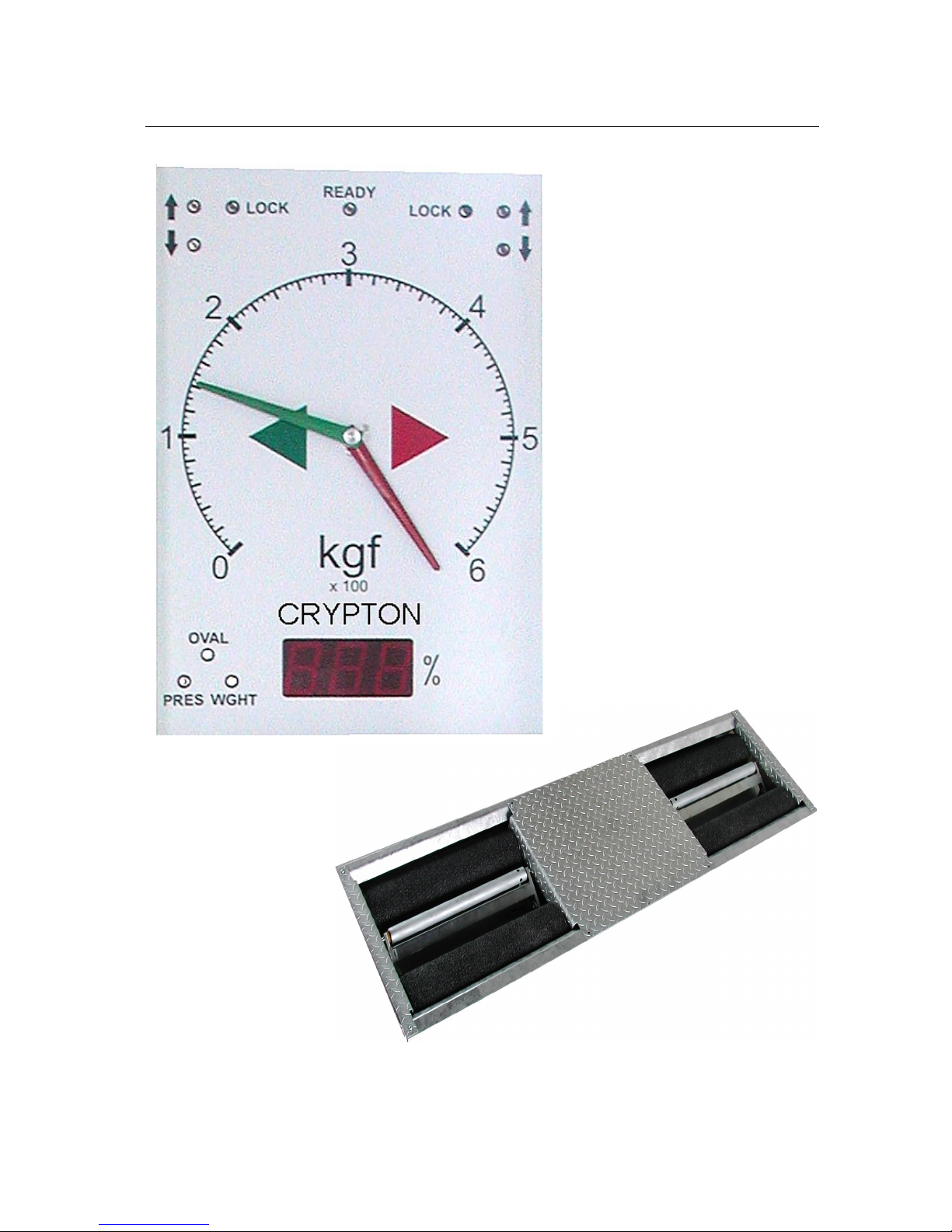
Pit unit
The rolling road consists of two sets of free roller pairs connected by a
chain and indirectly driven by two electric motors through gearboxes. The
gearbox is joined to the roller tester frame by a force transducer. During
the motor operation when the car is braking, the resultant force is
transmitted from the rollers to the brake force transducer. The outputs of
the transducers are monitored by the internal circuits and eventually
shown on the display as brake effort.
A small third roller is fitted between each pair of main rollers. These
perform two vital functions. Firstly to monitor the presence of a wheel in
the rollers so that motors can only be energised when a vehicle is present
and secondly to measure speed of the wheel that is being braked. This
ensures that the motors are automatically switched off when the tyre
starts to slip on the roller surface.
Page 7
660-R OPERATING INSTRUCTIONS Page 7
660-R MOT Class III and IV Roller Brake Tester
Page 8
660-R OPERATING INSTRUCTIONS Page 8
Control unit
The control unit contains front panel with:
Green indicator light : Car on rollers / Rollers drive direction / 4WD
(Arrows Lup, LDn, Rup, RDn)
Red indicator lights: Wheel locks (Lock left & Right)
Green indicator light : Ready for test (Ready)
Scale showing brake force:
Pointers: Green for left, red for right
Digital display (DDsp): Imbalance, ovality, pressure, weight
Amber indicator lights: Showing type of information on digital display
(Oval, Pres, Wght)
Inside: Power supply board for control computer, front panel,
amplifiers and motor control
Outside: Main switch, Emergency switch
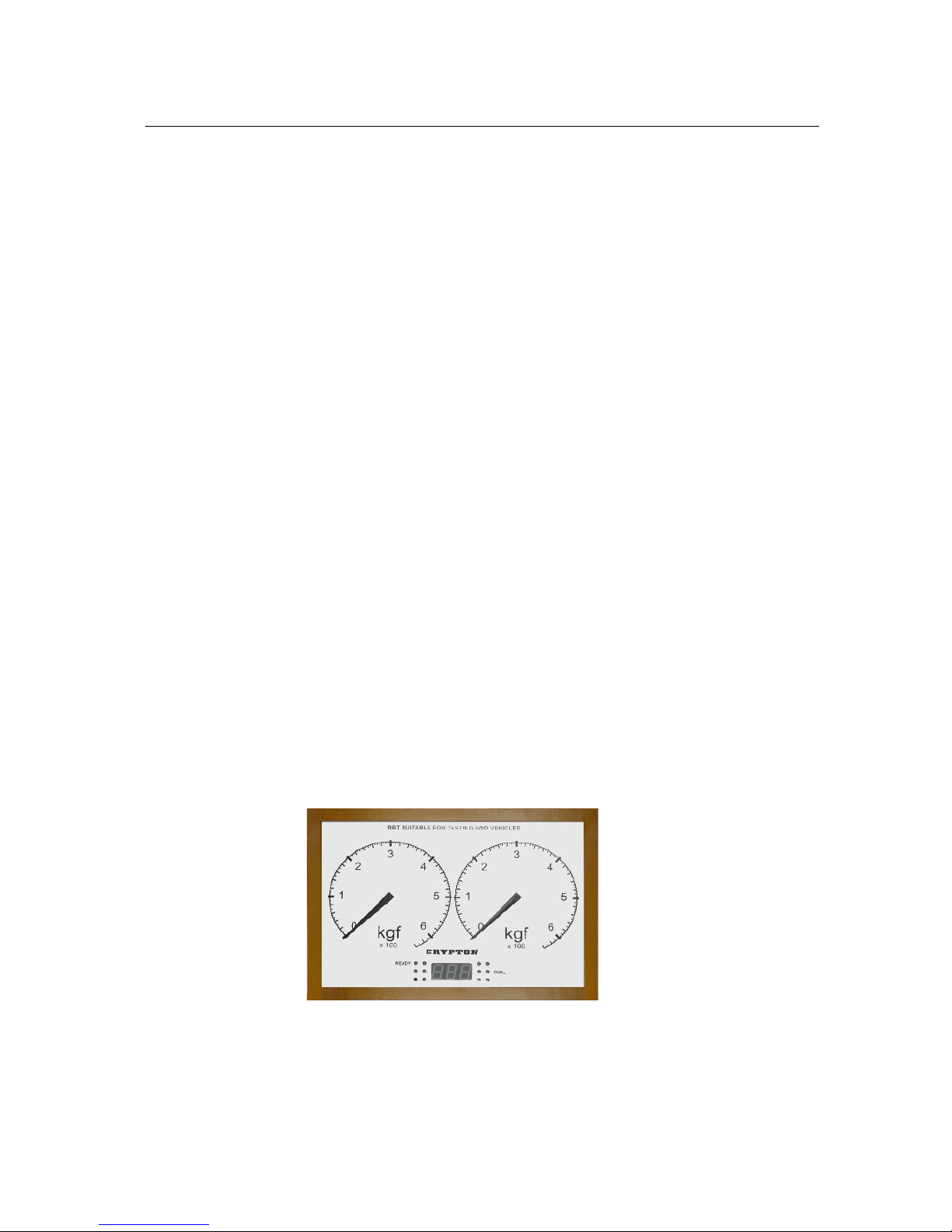
Alternative display
A twin dial display can be specified when ordering a 660-R and this has
two separate dials mounted side by side rather than the co-axial
arrangement. All scales and other indicators are identical as shown:
Printer
The printer is an optional device that can be specified at the time of
purchase or fitted later. Follow the instructions in the printer handbook
for loading paper and fitting ink cartridges (if applicable).
Page 9

660-R OPERATING INSTRUCTIONS Page 9
Remote control
Remote control consists of 16 keys, some of which have dual function
which are activated through the 2nd key.
START: Used to start the rollers
when the system is ready
for a test or restart during
a test.
STOP: Used to stop the rollers,
any roller that is running
will stop. To stop the test
completely, press OK
while the DDsp = STP
UP ARROW: Used for axle selection.
DOWN ARROW: Used for axle selection
OK: Press to save results
from the last test step.
LEFT ARROW: Used for wheel selection
RIGHT ARROW: Used for wheel selection
DIFF: Selects imbalance when
both wheels are running.
4WD: Used to switch test procedure into a special mode that rotates
wheels in opposite directions during all test steps so that prop
shaft does not rotate.
SEC: Used to initiate secondary brake test
PARK: Used to initiate parking brake test
OVAL: Used to initiate ovality measurement
WGHT: Used for weight input
AXLE: Used for axle selection
Page 10

660-R OPERATING INSTRUCTIONS Page 10
PRINT: Used to print test results
TEST: Starts both rollers so that vehicle can be driven out
2 nd: This key activates the second function of other keys
2 nd STOP: Will RESET the system and clear all previous results
so that a new vehicle test is activated.
When the system is RESET the DDsp shows CL4
2 nd WGHT: Allows manual weight entry. DDsp = At
Respond by pressing AXLE for individual axle weight entry or
TEST for gross vehicle weight. Enter the weight in 100kg units
i.e. 100 = 10 Tonnes. Then press OK
2 nd OK: System internal test, DDsp = TsT
Note: The Fn key is not currently used on this model.
Page 11

660-R OPERATING INSTRUCTIONS Page 11
GUIDE TO TESTING
General guide:
The START key starts the motors or motor as appropriate. This will only
happen with a car in the rollers as shown by the green Ready indicator
lamp being illuminated.
After START is pressed and while the motor(s) is getting up to testing
speed, the digital display will show rotating icon(s) to confirm which
wheel(s) is being started. Once this icon disappears, test actions or brake
force measurements can be taken.
Four actions will stop the rollers; if the STOP key is pressed, the car
leaves (even temporarily) one of rollers sets, wheel slip is detected or the
safety switch is activated.
With a car on the rollers and the rollers not running, one (or two) of the
green indicator lights LUp, LDn, RUp, RDn will flash to show the direction
in which the wheel(s) will be driven. Once the motor is started, the
flashing light will be stay on.
As the brakes are applied and a wheel approaches the pre-set slip limit,
the respective red Lock indicator will flash.
Any measured value will remain on the scale display (or DDsp) until the
OK button is pressed to accept the result. The pointer(s) will then be
returned to zero.
If the brakes are cold or wet, take the opportunity to apply brake several
times to warm up and/or dry brakes while the wheels are being centred.
Individual sections of the MOT procedure can be repeated if
unrepresentative readings have been obtained or the process is
interrupted for some reason. Simply press the START key again and
repeat the test section, only the results taken during the last sequence
will be stored when the OK key is pressed.
The normal testing method follows the MOT tester’s manual sequence but
the rollers can be used in Manual mode or specifically for testing one
wheel of motorcycles or three wheel vehicles – see later sections.
Page 12

660-R OPERATING INSTRUCTIONS Page 12
TEST DESCRIPTION
Use the following section as a prompt list when performing MOT tests. The
next sections gives a more detailed description and should be studied by
new users before any attempt is made to follow this simple prompt list.
MOT Brake Test Procedure for Class IV
Enter the car details onto the PC (if connected) or press WGHT key to
enter car weight
If the vehicle braking system is fitted with a servo, ensure the engine is
running at idle throughout the test (use exhaust extraction or adequate
ventilation).
RESET the system by pressing 2 nd and then STOP, DDsp shows CL4
Front Axle Drive the front axle into the rollers.
CENTRE THE WHEELS: Press START key to start both roller sets, DDsp
shows both rotating icons then Ctr. Move steering wheel to centre
wheels and press STOP when alignment is correct
FRONT LEFT BRAKE: Press START key to start only the left roller set.
DDsp shows left rotating icon then A1.L Apply footbrake smoothly
until the wheel stops or produces its maximum brake effort , then
press STOP.
(This start, test, stop action can be repeated if necessary)
Once acceptable reading has been obtained press OK to store the result.
FRONT RIGHT BRAKE: Press START key to start only the right roller set.
DDsp shows right rotating icon then A1.R Apply footbrake smoothly
until the wheel stops or produces its maximum brake effort , then
press STOP.
(This start, test, stop action can be repeated if necessary)
Once an acceptable reading has been obtained press OK to store.
BIND, OVALITY and IMBALANCE TEST Press START key to start both
roller sets. Do not apply any brake force. DDsp shows both rotating
icons then Fr.b for a few seconds. It will then show either the bind
value or symbol “--” if bind is below 20kgf.
Apply a brake force of about 100 kgf and hold pedal steady
Press OVAL key to measure the ovality, DDsp shows to, wait
6 second approx.
Page 13

660-R OPERATING INSTRUCTIONS Page 13
When DDsp shows BAL, the ovality measurement is complete, apply
footbrake smoothly up to about 90% of maximum force where imbalance
will be measured and then slowly release the pedal observing the force
readings. Press the STOP key to end the test. (This whole section can be
repeated if necessary).
Press OK key to save the results.
If the Parking brake is fitted to the front axle, test it now before
proceeding to Rear axle test.
Rear Axle: Press DOWN ARROW key to switch to the rear axle,
DDsp = rE
Drive the rear axle into the rollers.
CENTRE THE WHEELS: Press START key to start both roller sets,
DDsp shows both rotating icons then Ctr. Wait for the wheels to
centre and press STOP when alignment is correct
REAR LEFT BRAKE: Press START key to start only the left roller set.
DDsp shows left rotating icon then rE.L Apply footbrake smoothly
until the wheel stops or produces its maximum brake effort , then
press STOP.
(This start, test, stop action can be repeated if necessary)
Once acceptable reading has been obtained press OK to store.
REAR RIGHT BRAKE: Press START key to start only the right roller set.
DDsp shows right rotating icon then rE.r Apply footbrake smoothly
until the wheel stops or produces its maximum brake effort , then
press STOP.
(This start, test, stop action can be repeated if necessary)
Once an acceptable reading has been obtained press OK to store.
BIND, OVALITY and IMBALANCE TEST Press START key to start both
roller sets. Do not apply any brake force. DDsp shows both rotating
icons then rE.b for a few seconds. It will then show either the bind
value or symbol “--” if bind is below 20kgf.
Apply a brake force of about 100 kgf and hold pedal steady
Press OVAL key to measure the ovality, DDsp shows to, wait
6 second approx.
When DDsp shows BAL, the ovality measurement is complete, apply
footbrake smoothly up to about 90% of maximum force where
imbalance will be measured and then slowly release the pedal
observing the force readings. Press the STOP key to end the test.
(This whole section can be repeated if necessary).
Page 14

660-R OPERATING INSTRUCTIONS Page 14
Press OK key to save the results.
If the Parking brake is fitted to the rear axle, continue with the Paring
Brake Test.
Parking brake (applicable after both front and rear axles)
Press PARK key, DDsp = Pb.L
LEFT PARKING BRAKE: Press START key to start only the left roller set.
DDsp shows left rotating icon then Pb.L Apply handbrake smoothly
until the wheel stops or produces its maximum brake effort , then
press STOP.
(This start, test, stop action can be repeated if necessary)
Once acceptable reading has been obtained press OK to store.
RIGHT PARKING BRAKE:Press START key to start only the left roller set.
DDsp shows left rotating icon then Pb.r Apply handbrake smoothly
until the wheel stops or produces its maximum brake effort , then
press STOP.
(This start, test, stop action can be repeated if necessary)
Once acceptable reading has been obtained press OK to store.
The test is now complete
Print results (if fitted)
When all axles have been tested, press PRINT key to print the test
results.
Brake forces are printed if no vehicle weight has been entered.
If the Gross Vehicle weight has been entered, brake performance is
calculated and printed.
Page 15

660-R OPERATING INSTRUCTIONS Page 15
MANUAL TESTING
Class IV – Manual mode
In this mode, the roller direction can be selected. This enables a 'quick
check' following a brake repair or testing of 4WD vehicles.
N.B. Not all 4WD vehicles are suitable for roller brake testing.
Check manufacturers' data before testing and if in doubt use
a decellerometer on a road test.
RESET the system in the normal way by pressing 2 nd then STOP keys
and show CL4 on the DDsp.
Drive the vehicle into the rollers.
Pressing the 2 nd and then 4WD keys puts the unit into Manual Mode
which is indicated by DDsp showing MAn.
Next select the wheel(s) that is to be tested and the direction of rotation
by using the following buttons:
Repeatedly press the LEFT ARROW key to cycle through, no direction
(off), forward rotation and reverse rotation for the LEFT rollers.
Repeatedly press the RIGHT ARROW key to cycle through, no direction
(off), forward rotation and reverse rotation for the RIGHT rollers.
The direction of rotation for each roller set is shown by the indicator
lamps on the display .
Press the START key to start the selected wheel(s) and after the rotating
icon display a live reading of brake effort is shown on the pointer(s).
The test is stopped when the wheel slips, the wheel leaves the rollers, the
STOP button is pressed or the emergency switch is operated.
The pointer will then show the maximum brake effort recorded during the
test.
If the PRINT key is pressed this maximum reading will be recorded on the
printout.
To exit the manual mode, RESET the system by pressing 2 nd and then
STOP keys and the DDsp shows CL4 to show return to normal operation.
Page 16

660-R OPERATING INSTRUCTIONS Page 16
Class III - TESTING ONE WHEEL ONLY
When testing three wheel vehicles or motorcycles is necessary to use one
roller set only, the left side roller set. There is a safety lockout that
prevents the unused roller from being driven even if the third roller is
depressed.
RESET the system in the normal way by pressing 2 nd then STOP keys
and show CL4 on the DDsp.
Pressing the 2 nd and then LEFT ARROW keys puts the unit into One
wheel or Motorcycle Mode which is indicated by DDsp showing MOt.
Position the wheel in the LEFT roller and then press START. After the
rotating icon, a live brake test display will be shown on the pointer.
Rollers will stop when the STOP key is pressed, the wheel leaves the
rollers, the wheel slips or the emergency stop is pressed.
The pointer will then show the maximum brake effort recorded during the
test.
If the PRINT key is pressed this maximum reading will be recorded on the
printout.
To exit the One Wheel mode, RESET the system by pressing 2 nd and
then STOP keys and the DDsp will show CL4 indicating a return to normal
operation.
Page 17

660-R OPERATING INSTRUCTIONS Page 17
PROMPT SHEET – photocopy this page and use as a guide when
testing. Enter details onto the PC (if connected) or press WGHT to enter
car weight. Run engine if servo fitted. RESET the system by pressing
2 nd and then STOP
Front Axle Drive the front axle into the rollers.
Press START key to start both roller sets, centre wheels, press STOP
Press START key to start only the left roller set. Apply footbrake to
maximum and
then press STOP. Press OK to store the result.
Press START key to start only the right roller set. Apply footbrake to
maximum and
then press STOP. Press OK to store the result.
Press START key to start both roller sets. Wait until DDsp shows either
the bind value or symbol “--” Apply about 100 kgf and hold pedal steady.
Press OVAL key, DDsp shows to, wait 6 second approx.
When DDsp shows BAL, apply footbrake to about 90% of max and then
slowly release the pedal observing the force readings. Press the STOP .
Press OK key to save the results.
Test parking brake now if fitted to front Axle.
Rear Axle: Press DOWN ARROW key to switch to the rear axle,
Drive the rear axle into the rollers and repeat Centre, left, right, bal tests
as above.
Parking brake (applicable after both front and rear axles)
Press PARK key, DDsp = Pb.L
Press START key to start only the left roller set. Apply handbrake until
the wheel stops or produces its maximum brake effort, press STOP.
Press OK to store the result.
Press START key to start only the right roller set. Apply handbrake until
the wheel stops or produces its maximum brake effort, press STOP.
Press OK to store the result.
The test is now complete. Press PRINT key to print the test results.
Page 18

660-R OPERATING INSTRUCTIONS Page 18
CALCULATIONS
A rotary slide-rule type calculator is supplied with the unit and this should
be used to calculate the brake efficiency.
Alternatively a manual method can be used as follows:
Efficiency: Note the maximum brake force from each wheel in kgf, add
these numbers together and divide the result by the vehicle
weight in kg then multiply by 100.
This gives percentage brake efficiency.
Efficiency = (A + B + C + D) X 100 %
(Vehicle weight)
Imbalance: If brake forces on a particular axle are A kgf and B kgf
Assuming A is greater than B then
Imbalance = A - B X 100 %
A
Page 19

660-R OPERATING INSTRUCTIONS Page 19
MAINTENANCE
Before all the repairs, service work and adjustments always lock the main
switch of the device.
The construction of the equipment is simple and thus does not require
costly maintenance. It is necessary to keep it clean, draw up loose bolts
regularly control the wear of the anti-skid surface of the rollers and in the
case of larger wear to replace this material or replace the set of rollers.
Lubrication
The oil in the gearboxes does not have to be replaced until after 10.000
hours of service. The used gearbox lubricant is synthetic oil AGIP TELIUM
VSF320. Flange and ball bearings have to be refilled annually using a
lubricant grease (for example SKF LGMT2 or LKMT3).
If you are changing the lubricant, following instructions apply:
1. Remove the cover plates, chain tension assemblies and motors.
2. Lubricate the bearings of the rollers by pumping the grease through
into the bearings.
3. Lubricate bearings of the motors once a year. Lifting the rollers
allows a better access to the bearings.
4. Lubricate the chain with a suitable oil or a special grease at least
once a year.
5. Check the oil level in the gearbox.
6. Bolt the cover plates on.
Warning: The lubricating oils and grease are all oil base products and
to protect the environment it is important to prevent them leakage into
the pit. To avoid any possible adverse skin reaction, always use protective
gloves or barrier creams when working with oils and greases.
Consult the lubricant supplier/manufacturer if in doubt.
Chain tension adjustment
It is necessary to watch the wear of the chain and after its elongation to
replace it for a new one before the chain wheels are damaged. The chains
are pre-stretched and need very little adjustment. They are adjusted by
moving the front or rear roller or the motor.
1. Remove both cover plates of the roller units.
2. Check the chain tension, it should not deflect by more than 5 mm.
3. Tighten the chain by moving one of the rollers away from the other.
Loosen the bolts holding the bearing. Tighten the chain by turning
the adjustment bolts, and re-tighten the bolts.
4. Bolt the cover plates back on.
Page 20

660-R OPERATING INSTRUCTIONS Page 20
Other periodical maintenance
Due to a small number of movable parts it is not necessary, except for
tensioning the chain and inductive switch triggering control, to do any
adjustments on the equipment.
Daily:
Clean the cover plates of the roller units
Inspect and clean the rollers
Weekly:
Check the proximity of the middle metal rollers one at the time. The
display will show the respective Lup and Rup green indicating lights
on when this roller is pressed down. The roller brake tester cannot
start unless the middle metal roller is triggered pressed down.
Twice per year:
Remove all cover plates from the roller units.
Clean the pits from oil and dirt.
Check that the adjustment bolts support the main bearings
properly.
Check the motors for oil leakage.
Check that the chain deflection does not exceed 10 mm when
pressing by hand.
Replace the battery in the remote control.
Clean the surfaces of the remote control and the control unit.
Bolt the cover plates back in place.
Perform a full check of all functions.
Yearly:
At least once per year the service organisation should perform the
transducer and amplifier calibration adjustment.
Page 21

660-R OPERATING INSTRUCTIONS Page 21
TECHNICAL SPECIFICATION of 660-R
Maximum axle load 4,000 kg
Maximum brake force 600 kgf
Maximum pedal force 1,000 N
Roller surface speed 3.8 kph
Roller Diameter 204 mm
Roller length 700 mm
Distance between roller centres 390 mm
Roller project by 25 mm
Minimum wheel diameter 450 mm
Maximum wheel diameter 1,100 mm
Measuring system Strain Gauge Transducers
Dimensions:
Roller assembly Width 2,340 mm
Depth 680 mm
Height 340 mm
Control Unit Width 590 mm
Depth 480 mm
Height 1,750 mm
Weights
Roller assembly 360 kg
Control Unit 70 kg
Electrical supply:
Total load 12 VA
Electrical connection 3NPE~50Hz 415V / TN-S
Page 22

660-R OPERATING INSTRUCTIONS Page 22
AFTER SALES SERVICE
Apart from the routine maintenance and adjustments stipulated in this
manual the equipment must not be tampered with in any way. All further
servicing must be carried out only by an engineer from our Authorised
Agents. Failure to observe these conditions will invalidate the Guarantee.
On-Site Service / Overhaul / Spare Parts
If you require a Service Engineer to attend ON SITE, either due to an
equipment fault, or for machine calibration, or if the equipment covered
by this manual requires to be sent back for factory overhaul, or if you
need spare parts, please contact our Product Support Helpline at the
following number.
Tel: 01278 436225 Fax: 01278 436238
Overseas
Service abroad is provided by the agent from whom your equipment
was purchased.
Crypton provide information and contracts covering:
Car Data, Fault Code Information, Diagnostic Information, Technical
Topics, Software Support Contracts, Software Updates &
Accessories
Helplines
Crypton run an Equipment Helpline during normal office hours.
Tel: 01278 436225 Fax: 01278 436238
email: support@CryptonTechnology.com
A fully comprehensive Product Support Contract is also available
which provides additional assistance with equipment / technical
support. Please contact Product Support on the above Helpline no.
for further details.
Page 23

660-R OPERATING INSTRUCTIONS Page 23
Notes:
Page 24

660-R OPERATING INSTRUCTIONS Page 24
 Loading...