

Page 1

USER MANUAL
F200 ADSL USB MODEM
Page 2

.
Page 3

CONTENTS
1. Introduction 4
2. Specifications 4
2.1 ADSL Standards supported 4
2.2 Supported Protocols 4
2.3 Connections 5
3. Hardware Installation Procedures 5
3.1 Hardware Requirements 5
3.2 Preparing your network information 5
3.3 Configure the ISP parameters for your Windows XP 6
3.4 Driver Installation on Windows XP 7
3.5 Software Configuration 8
3.6 Connection to the Internet 11
4. Troubleshooting 13
Page 4

1. Introduction
F200 ADSL USB modem is a high performance and high-speed device that
provides a full rate ADSL modem with the superb reliability and is a complete
solution for home and office. The F200 ADSL USB modem can have a maximum downstream data rate of up to 8Mbps and an upstream of up to 1Mbps.
You can safely enjoy the new generation broadband Internet with the F200
ADSL USB modem. Included drivers for Win98/ ME/ 2000/ XP.
2. Specifications
2.1 ADSL Standards supported:
ñSupports ITU-T G.992.1(G.DMT) and ANSI T1.413 Issue 2
ñSupports G.992.2 (G.LITE)
ñAnnex A & B
2.2 Supported Protocols:
WAN
ñPPP over ATM (PPPoA) VC MUX
ñPPP over ATM (PPPoA) with LLC/SNAP
ñPPP over Ethernet (PPPoE) with LLC/SNAP
ñPPP over Ethernet (PPPoE) with VC MUX
LAN
ñBridged Ethernet (IP over ATM) with LLC/SNAP
ñBridged Ethernet (IP over ATM) with VC MUX
ñRouted IP over ATM with LLC/SNAP
ñClassical IP over ATM
This package includes:
ñF200 USB modem
ñ1 USB cable
ñ1 RJ11 telephone cable
ñ1 CD with drivers
ñ1 users manual
4
Page 5

2.3 Connections
USB – Connects the USB cable from the USB port of the F200 modem to the
USB port of the computer.
LINE – Connects the RJ11 telephone cable from the telephone line port of
F200 modem to the telephone plug..
LED indications:
POWER: After successfully installing the modem, the POWER LED light turns
on. It will stay on every time you start your computer.
3. Hardware Installation Procedures
3.1 Hardware Requirements
The following hardware is necessary to configure and use the F200:
ñRJ-11 (ADSL Ready) telephone Line
ñUSB cable (Included in the package)
3.2 Preparing your network information
To configure your ADSL modem smoothly, it is required that you contact your
ISP (Internet Service Provider) and acquire the following information:
Type of Mode Encapsulation used:
a. PPPoE, PPPoA, IPoA, Bridged or Routed.
DSL connection parameters:
b. For PPPoE or PPPoA, refer to Table 3 and fill-in all values (provided by your
ISP). During the driver installation, select ‘WAN’.
c.For Bridged, Routed, or IPoA, refer to Table 4 and fill-in all values (provided by
your ISP). During the driver installation, select ‘LAN’.
5
Page 6

Table 3 WAN (PPPoE/PPPoA parameters)
Information Value
PVC Settings VPI
VCI
Encapsulation (LLC ‹ VCMux)
Login Username
Information Password
Line Modulation Automatic ITU G.dmt or G.lite preferred
Automatic ANSI T1.413 i2 preferred
ITU (G.dmt or G.lite)
G.dmt
G.lite
table 4 LAN (Bridged/Routed/IPoA parameters)
Information Value
PVC Settings VPI
VCI
Encapsulation (LLC or VC Mux)
IP Information IP Address
Subnet Mask
Gateway IP Address
Preferred DNS address
Alternate DNS address (If available)
Line Modulation Automatic ITU G.dmt or G.lite preferred
Automatic ANSI T1.413 i2 preferred
ITU (G.dmt or G.lite)
G.dmt
G.lite
3.3 Configure the ISP parameters for your Windows XP
F200 is initially set to function on Annex B protocol (ADSL over ISDN). To
install the F200 based on Annex A protocol ( ADSL over PSTN), follow the
procedure below.
NOTE: THE FOLLOWING PROCEDURES APPLY FOR PPPoA MODE..
Table 5
Annex A
Driver Setup ‰È·Ï¤ÁÔ˘Ì WAN
Protocol PPPoA
Encapsulation VCMUX
Modulation Automatic ITU G.dmt or G.lite preferred
VPI 8
VCI 35
USERNAME test
PASSWORD test_passw
6
Page 7

3.4 Driver Installation on Windows XP
Step 1:
Windows will detect the newly installed device
and the screen below will appear after the
F200 USB ADSL Modem is attached to the
systems USB port.
Select "Install from a specific Location",
and click "NEXT".
Step 2:
Select "Include this location in the search"
and type d:\driver\Wan
(where D:\ the CD-ROM)
Note: If the protocol being used is Bridged,
Routed or IpoA, then type d:\driver\Lan
Step 3:
Click Continue Anyway.
This window appears only on Windows XP.
Installation continues
7
Page 8
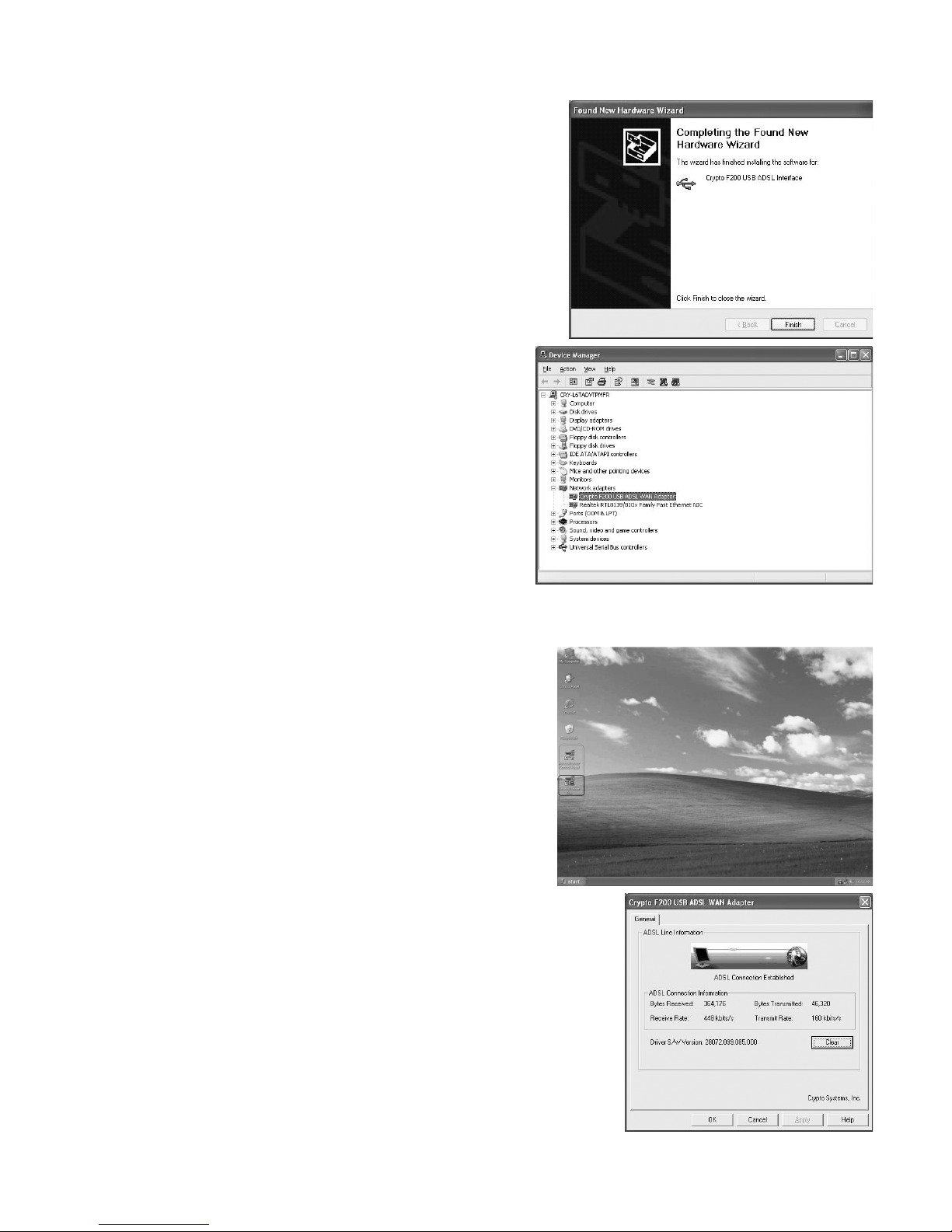
Step 4:
Click "Finish"
Step 5:
Left click on 'My Computer' icon and
click on 'Properties_ > _Device Manager'
Double click on Network adapters and
check to see for:
'Crypto F200 USB ADSL WAN adapter'
3.5 Software Configuration
Continue the setup process of the F200.
Step 1:
Double click on
the ‘Access Runner’ icon
Step 2:
Initially there is no connection / synchronization
with the ADSL line ‘Attempting to Activate Line’.
Press ‘ALT – P’ on your keyboard
8
Page 9

Step 3:
Here you can see that the connection has
not been established. ‘Attempting to Activate Line’.
Click the ‘Line Setup’ tab
Step 4:
Initially it is set to Annex B (ADSL over ISDN) as
shown on the bottom right.
Note: If the line was ISDN, then we do not change it.
Step 5:
Select Annex A (ADSL over POTS) (given that the line
was PSTN). Click Apply.
Note: Incase you take out the USB plug from your
computer and plug it back to the USB port of the
computer again (does not matter if its upon shut-down
or while the computer is on), then the Annex selection
will automatically be set to Annex B. To set it back
to Annex A, please follow this procedure again.
Select the Protocol Setup tab
Step 6:
In the Virtual Path Identifier (VPI) selection, and
under Virtual Circuit 0, the value is 0.
and
In the Virtual Circuit Identifier (VCI) selection, and
under Virtual Circuit 0, the value is 35.
9
Page 10

Step 7:
For the example insert:
VPI = 8
VCI = 35
Click Apply.
Step 8:
For Encapsulation Mode select the connection
protocol:
PPP over ATM VCMUX (RFC2364)
Click Apply
Click on the General tab
Step 9:
Under Line Status, the indication ADSL Connection
Established, indicates that the connection /
synchronization with the ADSL line has been done
with success.
Note: 1 to 2 minutes are required after you make
the above configurations, in order for the F200 to
be synchronized with the ADSL line.
Step 10:
To see information regarding the connection,
click the Physical Layer Statistics tab,
and click OK.
10
Page 11

Double click on the Access Runner icon
ADSL Connection Established indicates that the
connection / synchronization with the ADSL line
has been done with success.
Note: After power on the PC, it takes 1 to 2 minutes
in order for the F200 to be synchronized
with the ADSL line.
3.6 Connection to the Internet
Step 1:
To connect to the Internet, double click on the
Connect Access Runner DSL icon which is found
on the Desktop
Step 2:
Insert the "User Login & Password" that has been
given to you by your ISP, click Dial to connect.
Step 3:
Double click on the connection icon on the Windows toolbar.
11
Page 12

Step 4:
To ensure that the F200 has been successfully
installed, under the General tab, check to see that
Connected is indicated next to Status.
You can also check your connection
speed: Speed -> 448.0kbps.
Step 5:
Under the Details tab, you can see various
information regarding the connection.
(i.e. Server Type, Server IP address etc.).
12
Page 13

4. Troubleshooting
The POWER LED is not on
ñCheck to see that the connections between the USB port of the F200 and the
USB port of your computer are plugged in correctly.
Cannot access ISP
ñIf in PPPoA & PPPoE mode, check your login account and password for the
remote server.
ñCheck your VPI/VCI value and encapsulation mode are the same as your ISP
gave you.
ñTry to dial the phone to check if the phone line to CO is good if telephone
service is available.
Note: Incase you take out the USB plug from your computer and plug it back
to the USB port of the computer again (does not matter if its upon shut-down
or while the computer is on), then the Annex selection will automatically be set
to Annex B. To set it back to Annex A, please follow the procedure of Step 5
of 3.5 Software Configuration.
Reset (reset connection)
Restart the connection of the F200 modem by pressing ‘Stop’ and ‘Start’ in
the first window example of section 3.5.
Note: Check to see if it is successful or not.
13
Page 14

Declaration of Conformity
The 'F200 ADSL USB MODEM' is approved for use for within the European
Union, and the compatibility of this unit and it’s basic requirements are declared
with the CE symbol.
Passage extract of the authentic declaration of conformity:
CE Verification of Compliance
Technical Standards:
EMC: ETSI EN 300 386 v1.3.2/2002.12
LVD: EC LOW VOLTAGE DIRECTIVE 73/23/EEC, 93/68/EEC
Measurement standards:
(1) EN 55022 : 1998
(2) EN 61000-3-2: 2000
(3) EN 61000-3-3: 1995
(4) EN 61000-4-2: 1998
(5) EN 61000-4-3: 1998
(6) EN 61000-4-4: 1995
(7) EN 61000-4-5: 1995
(8) EN 61000-4-6: 1996
(9) EN 61000-4-11: 1994
(10) EN 60950 : 2000
Measurement Facilities: BEST LABORATORY CO., LTD.
Note: Specifications are subject to change without prior notice.
Page 15

.
Page 16

www.crypto.gr
 Loading...