

Page 1
CRYPTAG
CENSUS
LABEL READER
TYPE ELC 1
Identec Ltd Tel: 0 (044) 191 584 4084
Mercantile Road Fax: 0 (044) 191 584 9077
Rainton Bridge Industrial Estate Tech Support: 0800 018 1661
Houghton-le-Spring www.identec.co.uk
County Durham e-mail: [email protected]
England [email protected]
DH4 5PH
Issue 2, July 2000
Page 2
Page 1 of 21
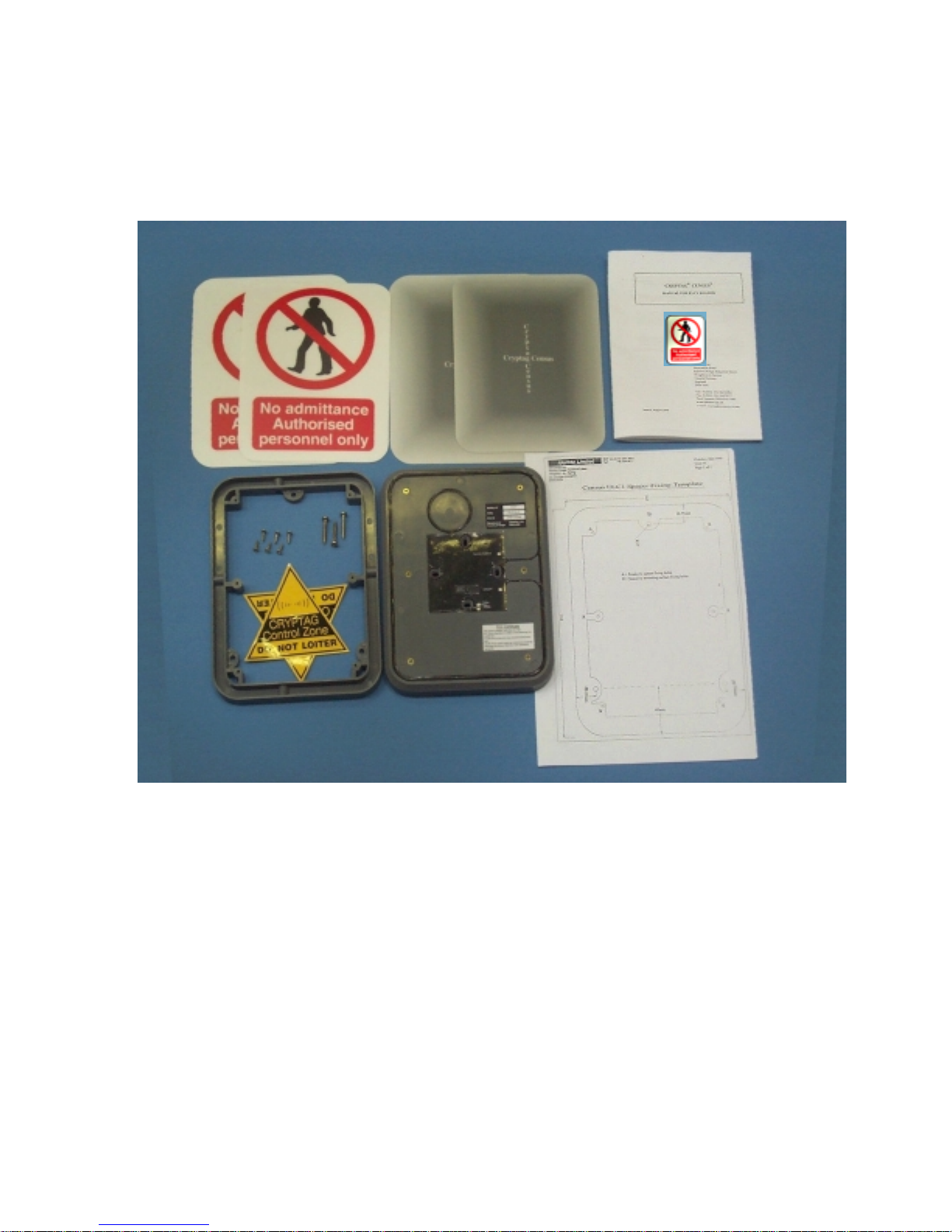
Complete ELC Reader Kit
1
Page 3

Page 2 of 21
This manual is provided for information purposes only. All information included in this manual is subject
to change without notice. Identec is not responsible for any damages, direct or indirect, arising from or
related to the use of this manual, or associated product.
© Copyright 1999 Identec Limited. All rights reserved.
Printed in the United Kingdom.
This manual may be reproduced by Identec's customers for the purpose of assisting with the
installation of Cryptag Census equipment. Reproduction in any form, physical or electronic, of
all or part of this manual for any other purpose requires the express written permission of
Identec Ltd.
Trademark Notice:
Cryptag is a registered trademark of Identec Ltd.
Census is a registered trademark of Identec Ltd.
Cliptag is a registered trademark of Identec Ltd
Identec is a registered trademark of Identec Ltd
Patents:
Patents in the UK and other countries protect Cryptag systems.
Registered Designs
Various aspects of the reader design are registered.
WARNING NOTICE
This product uses radio frequency signals, and is therefore subject to possible interference. Any
application should bear this in mind, and in particular it should not be possible for personal safety to be
jeopardised by a failure to read.
This reader neither uses nor generates hazardous voltages. You should not connect any such vol tage to it.
2
Page 4

Page 3 of 21
This product complies with the following European Community directives:
1
Low Voltage Directive. (73/23/EEC)
EMC Directive. (89/336/EEC)
FCC Regulations
This device complies with Part 15 of the FCC Rules, but approval is pending. Operation is subject to the
following two conditions:
(1) this device must not cause harmful interference, and
(2) this device must accept any interference received, including interference that may cause undesired
operation.
FCC Identifier: Application 15 JHD-CEN5
Note:
Systems that comply with FCC regulations operate at different frequencies, and only such systems are to
be installed in USA. These systems have some performance differences (in particular a slight increase in
reading speed). Throughout this manual, the effect of the change in frequency is noted, e.g. “131kHz (in
USA, 153kHz)”. The part numbers of readers and tags for use in USA has an “A” added, so the US
version of ELC1 is ELC1A.
1
For more information on approvals, refer to Appendix B.
3
Page 5

Page 4 of 21
CONTENTS
C hapter 1 Crypta g C ensus L abe l Rea der P a g e
1.1 Introduction 5
1.2 The reader 5
1.3 Unpacking 5
1.4 Getting started 5
Chapter 2 Reader Location 6
Chapter 3 Installing and commissioning 7
3.1 Installation 7
3.2 Commissioning 9
Chapter 4 Troubleshooting 10
A p pendix A Techn i c a l Da ta 12
Appendix B Approvals 13
Appendix C User Instruction 14
Index 15
4
Page 6

Page 5 of 21
1. CRYPTAG CENSUS LABEL READER
1.1 Introduction
Cryptag Census is a high performance tag identification system, offering fast long range multiple reading
with the CR1 readers. Complementing the top end CR1 readers and short range EC1 range of readers, the
ELC1 (ELC1A-USA) reader provides a mid-range solution where moderate reading range is required.
The ELC1 is easy to install, and its thin profile means it can be mounted unobtrusively, for instance on
doors.
All Census Tags work on all Census Readers.
For most applications the instruction sheet provided with each reader should suffice. Installers should
rarely (if ever) need to refer to this manual, which should be treated as a reference document. This
manual complements the Cryptag Census Site Manual, which for instance contains data on the Census
tags.
1.2. The ELC1 reader
A Cryptag Census reader identifies tags (sometimes referred to as tokens or cards) using low frequency
radio signals. ELC1 transmits to the tag at 131kHz (in USA 153 kHz) and detects the tag’s response
which is at 98kHz (in USA 115kHz). The USA version is denoted as ELC1A.
The ELC1 reader is configurable, and this is normally done in the factory. Configuration controls the
output format, ti mings etc.
1.3 Unpacking
Check the following list of contents
Reader
Spacer
Labels
Manual
Mounti ng kit
1.4 Getting started
1. Connect a power supply to the reader.
The positive connection goes to V+ (terminal 1), while the negative connection goes to 0V (terminal 2).
The supply should be at least 5V, and should not exceed 18V. For optimum range the supply should be at
least 12V. For supply voltages less than 12V reading range will be reduced.
2. Bring a tag near the reader.
The reading range should be at least 100cm (39 inches) for a TC1 tag, but is usually more. (Reading
range is reduced unless terminals 3 and 4 are connected.)
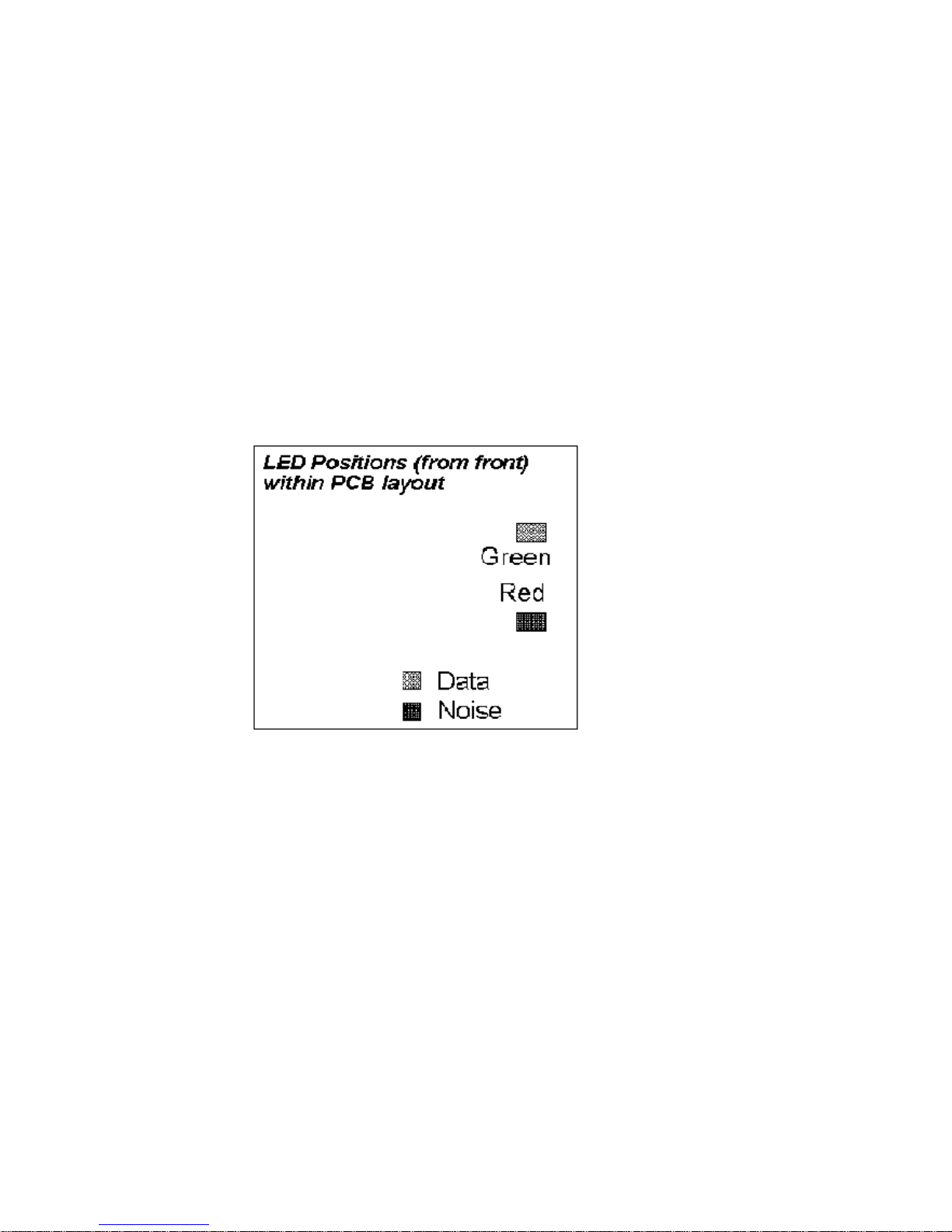
3. The red LED 2 (see page 9) will flash when the tag is within range.
The red LED 2 will flash when the tag is being read. At the same time the red “Noise” LED 4 will
flicker, and the flickering gets more intense as the tag gets closer to the reader. The green “Data” LED 3,
and will blink once when the tag’s identity is reported.
4. The reader reports the tag only once.
The reader sends the identity of the tag when the tag is first identified. (As shown by the Data LED 3
blinking). To get another report, take the tag away from the reader for a few seconds, then bring it back
in towards the reader.
5
Page 7

Page 6 of 21
2. READER LOCATION
The range of the ELC1 is such that some care is needed in selecting the reader’s location.
A Do not locate an ELC1 reader near another reader. If tags can pick up signals from two or more
readers, they respond to neither. The separation should be about 1.5 times the sum of their
ranges. For the ELC1 reader the reading range is normally well over 1 metre (3.3 ft), so two
ELC1 readers should be kept at least 3 metres (10 ft) apart.
If there are readers from other manufacturers there may be an interaction. If the other reader
uses frequencies similar to those used by Cryptag Census the safe distance may be more than
expected. (This is because Cryptags are more sensitive than most tags.)
B ELC1 readers should not be mounted directly on to a metal surface. Not only will the reading
range be severely affected, but also the current consumption will rise. (In extreme cases there is
a danger that the reader may cut out temporarily.)
It is safe to mount on metal using the spacer provided but reading range will be affected.
The reader can be mounted on metal backboxes 75mm square (such as are used for standard
electrical fittings). It is better to use plastic backboxes, as the metal backbox has a small effect
on range.
Take care not to over-tighten backbox attachment screw/bolts.
C Interference. The reading range may be affected if the ELC1 is mounted close to a computer
monitor, or other sources of interference. (The effect on reading range will vary with the
monitor’s scan frequency.)
D ELC1 readers can be mounted on glass or other flat surfaces using the spacer provided.
The ELC1’s reading range is such that a Site Survey is desirable. Using the MS3 Test/Tune meter, the
reading range will only be affected significantly if the MS3, with the probe attached, shows that the
reading range is reduced below 1 metre.
ELC1 Label readers are designed so that they can be mounted directly on to a door. The reader’s
dimensions match those of commonly used labels (signs), and the reader’s low profile and bevelled edges
mean that it can be mounted unobtrusively. Using the spacer supplied, the reader can be mounted on
other surfaces.
In general the reader is best mounted in the centre of a door, or towards the handle. This maximises the
probability of the tagholder being detected before reaching the door. The reader can be mounted on either
side of the door. Check that no problems will arise from tags being read behind the reader or to the side.
(The reading zone is almost spherical.)
When tags are being carried by people, the best height should be selected with regard to the way in which
tags will be read.. The best height is generally where tags will naturally be presented face on to the reader
(except TC3). The reader should be within reach of people in wheelchairs.
ELC1 readers have LEDs fitted, but in some cases they will be covered by the label (sign).
The ELC1 requires a hole to be drilled in the surface on which it is to be mounted. This hole should be
45mm (1.75 inch) diameter, and have a depth of at least 10mm). If the reader is to be mounted on a fire
door, make sure that the door’s integrity is maintained.
If the reader is to be mounted in an outdoor location, you should use a suitable version of the reader.
6
Page 8
Page 7 of 21
3. INSTALLATION AND COMMISSIONING
3.1 Installation
Cabling
Use screened cable, with the cable screen earthed at the other end from the reader (the controller end).
Preferably the cable should not be more then 100 metres (330 ft) long for Wiegand interface, or 10
metres (33 ft) for the RS232 interface.
Positioning the reader and labels
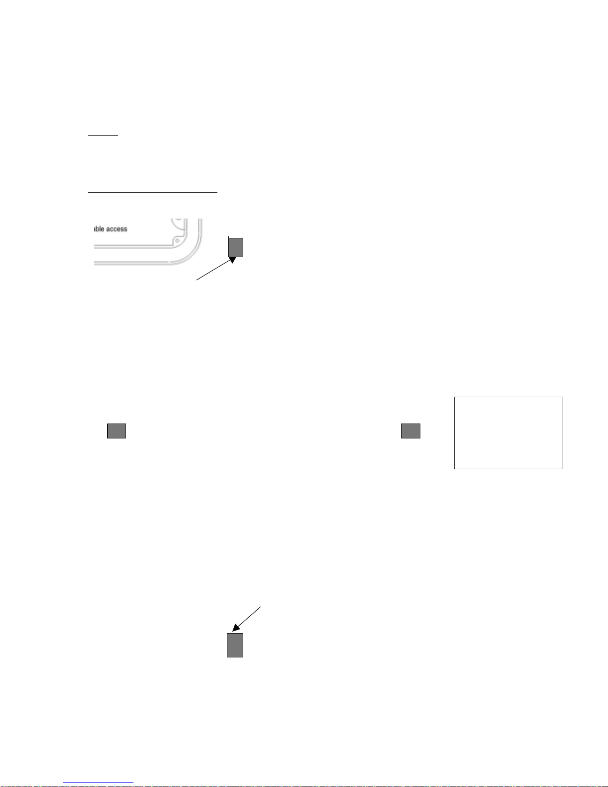
The ELC1 reader is supplied with a spacer and a number of labels to suit different mounting locations.
Use the spacer where it is not possible to drill a hole for the reader.
B
B
A
B
B
Spacer
correctly
polarised
B
Fixing to Glass:
position with the cable running through one of the four Cable Access Points.
After electrical connections have been made to the reader attach it to the spacer using the screws
provided.
The labels are fitted last. Using double sided sticky tape, locate and fix the spacer in
AA
B
7
Page 9
Page 8 of 21
After testing attach one label to the reader and for decorative purposes, another label on the other side of
the glass.
If the reader is to be mounted directly on to the door or wall, a hole 45mm diameter, and at least 10mm
deep should be drilled at the centre of the desired reader position. An additional hole will also be needed
to bring in the cabling to the reader.
Connections
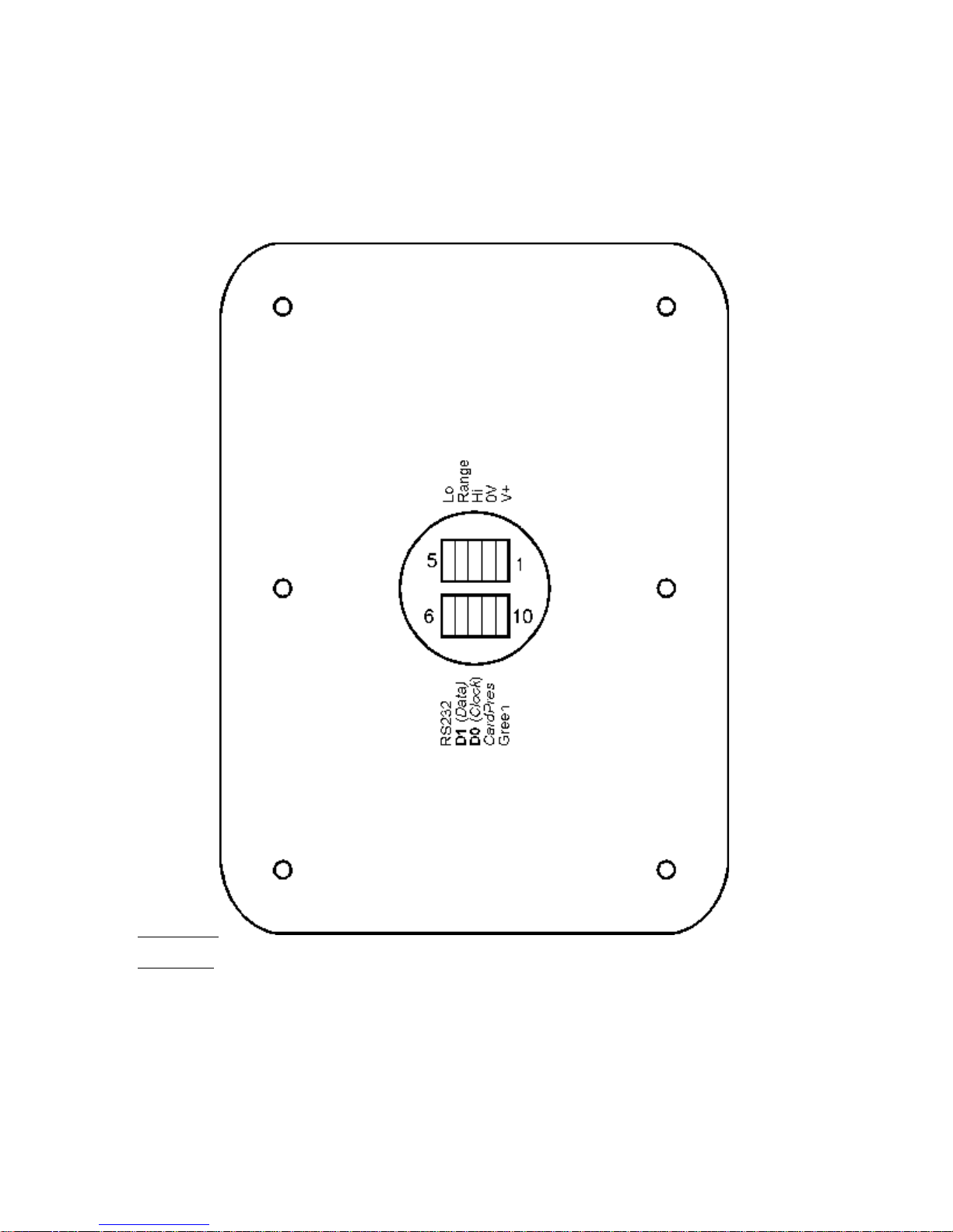
The connections are shown above.
The power supply to the reader (between 0V and V+) should be between 5V and 18V d.c.. The current
consumption of the reader is approximately 60mA, so voltage drop in the cable should be considered but
will rarely be a problem.
The connections marked “Hi”, “Range” and “Lo” (terminals 3 to 5) allow the reading range to be
adjusted. If Range is linked to Hi the reader will give full range, while connecting Range to Lo reduces
the range to approximately 60%. Do not leave these unconnected, and do not connect them to anywhere
8
Page 10
Page 9 of 21
else. (Leaving Range open circuit will give an intermediate reading range, but there is a danger that
reading will be unreliable.)
The green LED will light when the LED input is grounded.
Readers can be configured as either Wiegand output or Clock/Data output. The same data connections
are used, as shown in the drawing. The RS232 output is independent and it can be configured to give data
after all tags. Card Present (CardPres) is available when the reader is configured for Clock/Data output,
and goes low while data is being transmitted. (The Card Present terminal can also be reconfigured as a
Wiegand Hold input ter minal.)
The ELC1 has some protection against connection faults, but they do not cover all circumstances.
3.2 Commissioning
Commissioning the ELC1 is a simple process, consisting of first making sure the reader is working, and
then checking that the data from the reader is reaching the controller.
To check that the reader is working, apply power to the reader. The red LED should come on, as also
should the Data LED. The Noise LED should be off. Bring a tag in towards the reader. Three things
should happen.
The red LED should start to flicker, showing that the tag is being read.
The Noise LED will flicker, and the flickering gets stronger as the tag gets closer to the reader.
The Data LED will flash when the tag is first read. This shows that tag data has been sent. To
get the Data LED to flash again, remove the tag, wait for a few seconds, and then bring it back
in.
Verify that the tag data is reaching the controller and that the green LED (if used) is being driven by the
controller.
The reading range should be at least 90 cm (3ft) if long range is selected (Range connected to Hi) and the
typical range is 1.1m to 1.2m (up to 4ft). With the range reduced (Range connected to Lo) the reading
range should drop to 60 to 70 cm (about 2 ft).
If there are any problems, refer to the Troubleshooting guide in the next section.
9
Page 11

Page 10 of 21
4. TROUBL ESHOOTING
It is rare for the reader to fail, so check the installation as well.
No LEDs come on
This will normally mean that the reader is not receiving power of the correct polarity. Check the voltage
on the reader terminals using a meter.
If there is very bright light, it may not be possible to see the LEDs. If this is the case, the reader may need
relocating.
If the LEDs are still not coming on, replace the reader.
Red LED does not flicker when a tag is brought in, OR
Data LED does not flash when a tag is brought in.
This suggests that the tag is not being read.
Make sure that the tag you are using is a working Cryptag Census tag.
Is there another reader in the vicinity?
See the section on reduced range.
Red LED flashes, but no response by controller (i.e no output message)
Does the Data LED flash when the tag is brought in to the reader? If not check whether this tag is valid
for the reader? An ELC1 may be configured to report some tags and ignore others.
Is the tag being removed from the reading zone for sufficient time? Normally a few seconds will be
sufficient, but it is possible for the ELC1 to be programmed to wait for longer. (In this case you should
have been informed.)
Data LED flashes but there is no controller response
Check the wiring to the controller.
Has the controller been programmed to respond to the tag being used?
NB If the power supply to the reader has had incorrect polarity, there is a small chance that the output
circuit has been damaged.
Tags are read, but range is low
Check the Noise LED. This should be off when no tag is present. Any flickering on the Noise LED is
likely to mean that reading range will be affected. (If the noise LED is off it doesn’t ensure that there is
no interference, but the reading range will usually exceed 90cm.)
Is there another reader nearby?
Is there a computer monitor nearby?
Is the reader mounted on metal? The ELC1 is not designed to be mounted on metal.
Is Range (terminal 4) connected to Hi (terminal 3)?
10
Page 12

Page 11 of 21
Are there any other electrical systems that could cause interference. Try turning electrical equipment off
to see if the reader is affected.
Green LED does not come on
Disconnect any wires to the LED terminal, and connect a wire from the 0V terminal to the LED terminal.
The green LED should come on. If it does, check the wiring to the LED terminal.
Does the signal to the LED terminal have the correct polarity? (connect to 0V to turn on.)
Tag numbers reported incorrectly (Wiegand)
The most likely cause is the Wiegand wires are reversed.
Is the controller set up for the format used by the reader? If the system uses Site Codes, are these set up
correctly?
Tag numbers reported incorrectly (RS232)
The reader is supplying data switching from 0 to +5Volts and as such is not true RS232.
Tests have
shown that this is compatible with most modern computer terminals.
If the data appears to be garbage, check the baud rate etc. The normal for EC1 readers is 9600 baud, 8
data bits, one stop bit, no parity.
Check that the RS232 line is not too long, and check that connections are properly made. This will often
give occasional errors.
Repair
The reader is designed to be "Installer-Friendly", and is rarely damaged, so please check the
installation thoroughly. In the unlikely event that you find that the reader is faulty, you should
replace the entire reader.
Identec encourages its customers to return faulty equipment, as investigation of faults may help
us improve the product.
12 month "no-quibble" guarantee
All Identec readers and tags are guaranteed for 12 months from the date of despatch from the
factory.
11
Page 13

Page 12 of 21
Appendix A TECHNICAL DATA
For more information on Cryptag Census in general, refer to the CR1 Site Manual.
The reading range of ELC1 is specified at 90cm minimum with a TC1 tag, but in general better ranges
will be achieved. (Typical ranges are 1.1 metres to 1.2 metres.) This range assumes that the tag is in the
optimum orientation.
Reader mechanical de tails
Dimensio ns 213mm x 163mm x 4.7 mm
8.4 x 6.4 x 0.2 inches
Weight approx 200g (7 ounces)
Colour/Material Grey ABS case.
LEDs Red (internal control)
Green (external control)
Noise indication (red)
Data sent (green).
Electrical connections
Screened cables are required to meet EMC requirements, as approvals were obtained with
screened cables.
Power input.
5-18V d.c. 60mA typical. (current depends on LED status.)
The ELC1 power connection is reverse voltage protected. There is a slight danger that incorrect
connections on other terminals can damage the reader.
Wiegand output
Data on D0 and D1.
Low going pulses 100µs long. (All timings are potentially configurable.)
1.6ms pulse separation
Minimum 250ms between transmissions.
Internal 1k pull-ups.
Clock/Data output
This uses the same circuitry as the Wiegand output.
RS232 (NOT TRUE RS232)
Operates 0Volts Pulsing to +5Volts
Transmit data only. No receive function.
9600 baud, 8 data bits, no parity, one stop bit.
The reader reports a power up message, identifying itself.
Each tag is reported in ASCII code, e.g. HID=0014 PID=1234
The numbers are reported in hexadecimal.
1 0 0 mA max.
Configuration
ELC1 readers are normally configured by Identec. For advice on equipment to configure ELC1
readers, contact Identec.
Operating Environment
-20°C to +60°C non-condensing. (Standard readers)
Protected readers are available.
12
Page 14

Page 13 of 21
Appe ndix B APPRO VA LS
ELC1 generally requires some form of approval, as it is an intentional emitter of radio frequency. This
section describes the status of the product in various countries at the time of writing. For more up to date
information contact Identec.
Unit e d Ki ng do m
ELC1 is approved to MPT1337 and ETS 300 683
Other countries inside European Union
ELC1 is tested to ETS 300 330, for Radio Frequency emissions. The testing to ETS 300 330 and ETS
300 683 should be acceptable in all European Union countries. However certain national limitations may
apply.
United States of America
FCC Identifier: JHD-CEN5 applied for
For the purpose of FCC, this range of product is classified as a low frequency intentional radiator. "The
user is cautioned that any changes or modifications not expressly approved by the party responsible for
compliance could void the user's authority to operate the equipment."
---------------------------------------------------
In all countries, this product is approved on the basis that it shouldn't cause interference to others, and
that it won't be affected by interference. If you make an unauthorised modification, you may invalidate
that approval, and you might be committing an criminal offence (depending on local legislation).
Low Voltage Directive
Cryptag Census readers have been designed and manufactured in accordance with EN60950, following
the provisions of the Low Voltage Directive.
ISO 9002
Identec's Quality System conforms to ISO 9002. (Certificate Number - FM36029)
13
Page 15

Page 14 of 21
Appendix C USER INSTRUCTIONS
C.1 After installing Cryptag Census
, it is a good idea to make sure that the customer understands
how the system works, and how to get the best out of it. What they are told depends on the type of
application. This section provides information that will be useful to the manager responsible for the
system, as well as the basis for information to give to all tagholders (if applicable).
If personnel are carrying tags, show them how to present a tag to a reader face on. Explain that tags are
much less likely to be read if they are on their side (for instance lying in the bottom of a bag).
Tags do not read as well inside bags with metal frames, or surrounded by keys and coins. The identity of
the tag will not be incorrectly reported, but the range may be affected.
Once a tag has been reported, most software versions will not report that tag again until it has been taken
right out of the reading zone for several seconds, then brought back. If you need the door to unlock again,
you must walk well away from the reader before returning to it.
Tags must not be left within range of readers. The battery inside the tag will be used up. If the tag is left
next to a reader for several weeks the battery would become totally flat.
C.2 Tag disposal
When a tag reaches the end of its life, it should be disposed of properly. As there may be considerable
time before this happens, and environmental policy may have changed in the meantime, we recommend:
Tags contain a small lithium battery, and should be disposed of accordingly.
If you are uncertain about how to dispose of tags, they may be returned to Identec for disposal.
C.3 End User Instructions
This section can be used to generate simple instructions for end users.
You have been provided with a Cryptag Census tag.
Application information to be given here.
To get the best out of your tag, would you please spare a few moments to read this.
The tag operates best when it is in the same plane as the readers, which are usually mounted vertically.
You will get good performance if the tag is worn vertically, but not so good if the tag is placed flat in the
bottom of a bag.
The performance of the tag will be affected if it is surrounded by metal objects such as coins or keys.
(The larger the metal object, the more effect it can have.)
This tag has been designed and built to work under conditions met in normal daily use, but for reliable
operation the following precautions should be observed:-
1. Do not bend the tag excessively. It should not be kept in the back pocket of trousers, or other
places where it may be subject to bending.
2. Do not immerse in water, or allow it to come in contact with solvents.
3. Do not leave the tag in a hot place (e.g. on a radiator).
4. This tag contains a small battery, which under normal circumstances will last 5 years. Battery
life will be reduced if the tag is left for long periods within range of a Cryptag Census reader.
14
Page 16

INDEX
A
approvals, 13
ASC1, 12
B
backbox, 6
battery, 14
baud rate, 11
C
case, 12
clock/data, 12
commisioning, 10
computer, 10
configuration, 12
connections, 12
contents, 5
Page 15 of 21
D
E
F
G
data LED, 5, 10, 12
dimensions, 12
disposal of tags, 14
drilling hole, 6
EMC directive, 3
EN 60950, 13
environment, 12
ETS 300 683, 13
ETS 300 330, 13
fault-finding, 10
FCC, 3, 13
FCC identifier, 3
getting started, 5
green LED, 5
guarantee, 11
H
height, 6
hexadecimal, 12
HID, 12
15
Page 17

I
J
K
L
Page 16 of 21
installation, 8
interference, 6
introduction, 5
ISO 9002, 13
kit mounting, 5
Label, 6
LED’s, 5, 6, 10, 12
Lithium, 14
location, 6
low range, 10
low voltage directive, 3, 13
M
N
O
P
mechanical data, 12
metal, 6
monitor, 10
mounting, 6
mo untin g kit, 5
MPT 1337, 13
MS3 test/tune, 6
Noise LED, 5
operating temperatures, 12
outdoors, 6
patents, 2
PID, 12
power, 5
programming option, 10
Q
R
reader, 5
16
Page 18

S
T
Page 17 of 21
reading range, 6
red LED, 5
RS232, 11, 12
safety, 2
separation of readers, 6
serial data, 11, 12
site codes, 11
site survey, 6
spacer, 6
starting, 5
supply voltage, 5
tag disposal, 14
tag numbers, 11
tags, 5, 14
technical data, 12
temperature, 12
trademarks, 2
U
V
W
X
Y
Z
unpacking, 5
user instructions, 14
Voltage, 5
warning, 2
weight, 12
wheelchairs, 6
wiegand, 11
17
Page 19
Page 18 of 21
Sales Literature
18
Page 20
Page 19 of 21
19
Page 21
Page 20 of 21
20
Page 22
Page 21 of 21
21
 Loading...