

Cryo-con 26 Quick Start Manual
A Quick Start Guide to the Model 26
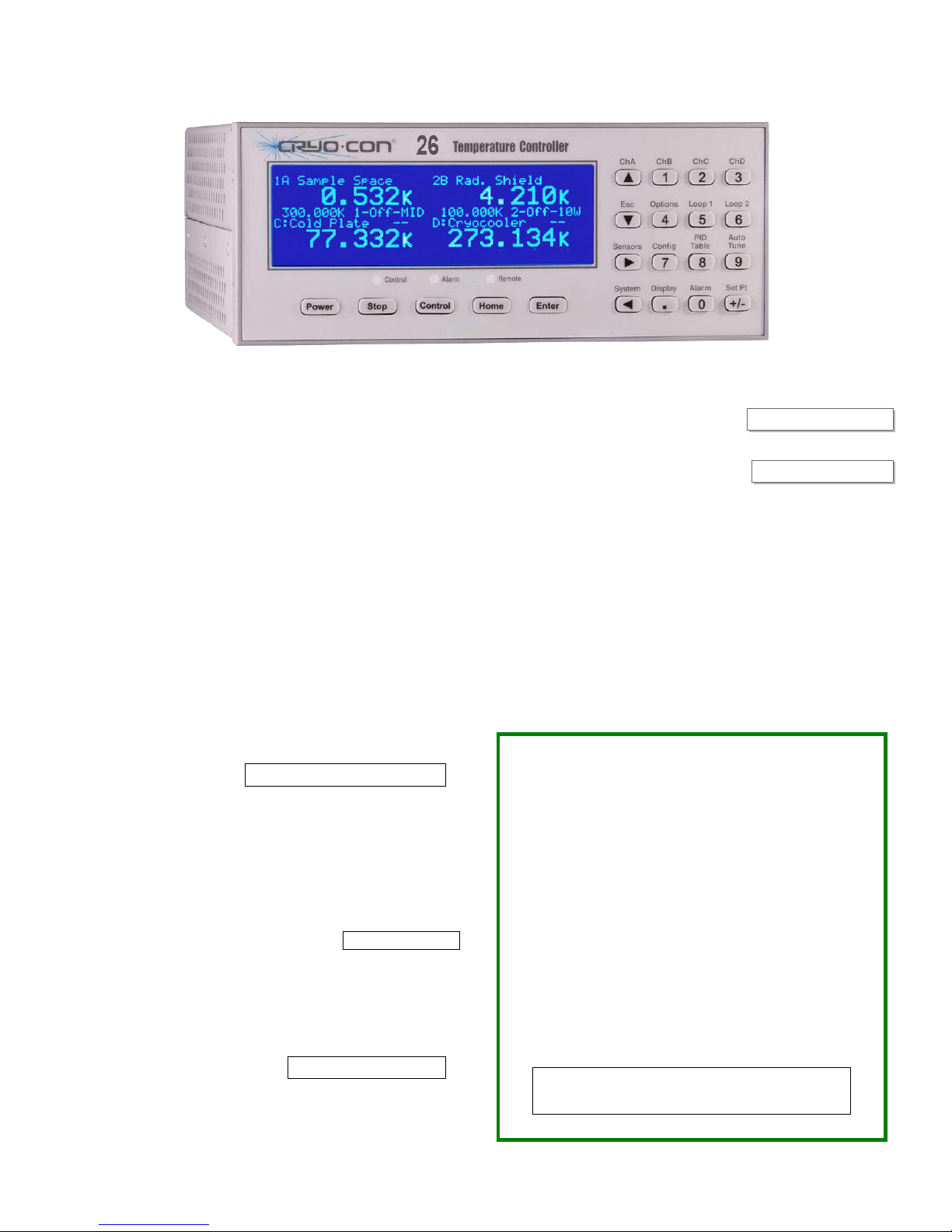
BASIC FRONT PANEL OPERATION
Pressing the Power key will toggle the controller's AC power on and off.
This key must be pressed and held for two seconds.
Pressing the Stop key will immediately disengage both control loops.
Pressing the Control key will engage them.
Pressing the Home key will return the screen to the Home display from
anywhere in the sub-menus. The Home display is the primary display for
instrument status and can be configured by pressing the Display key.
CONTROL LOOP SETPOINTS
To access the setpoint for the control loops, press the Set Pt key and
then use the navigation keys to select Loop #1, 2, 3 or 4. Use the keypad
to enter the desired setpoint and press the Enter key to set it and return
to the Home display.
CLEARING A LATCHED ALARM
During an alarm condition, the Alarm LED on the front panel will light and
an audio alarm will optionally sound. To view the status of all alarms,
press the Alarm key. To reset a latched alarm, press the Alarm key and
then the Home key.
DISPLAY OPTIONS
The display time constant and display resolution fields may be accessed
by pressing the System key.
The Display TC field is used to smooth temperature data with filters from
0.5 to 64 seconds. This is useful in noisy environments to provide stable
readings.
The display resolution field,
Display-RS is used to set the number of significant digits shown in
temperature displays. Settings 1, 2 ,3 or Full.
CONFIGURING A TEMPERATURE SENSOR
To configure an input channel for a specific temperature sensor, press
the ChA key for input A, or the ChB key for input B.
The first line of this menu is used to change the sensor units. An example
is shown here. Change the sensor units by using the + and 0 keys. When
the desired units are shown, press the Enter key to make the selection.
The current temperature is continuously
displayed.
Next, go to the sensor selection field and use the + and 0 keys to scroll
through the available sensors. When the desired sensor is shown, press
the Enter key to make the selection.
For advanced information on sensor configuration, see the user’s manual
section titled “Configuring a Sensor”.
For advanced information on sensor configuration, see the user’s manual
section titled “Configuring a Sensor”.
+
+
+
ERROR DISPLAYS
A sensor fault condition is identified by a temperature display of seven
dash (-) characters as shown here. The
sensor is open, disconnected or shorted.
If a temperature reading is within the measurement range of the
instrument but is not within the specified
sensor's calibration curve, a display of seven
dot (.) characters is shown.
Overtemp indicates that the controller’s Internal Temperature Monitor
circuit shut off the heater. This fault is usually the result of a shorted
heater or use of a heater. After the controller has been allowed to cool to
an acceptable temperature, pressing the Control key will clear the error
and restore control mode.
OTDisconn indicates that the heater output was disconnected by the
Over Temperature Disconnect Monitor. This monitor is configured by the
user and functions to disable the heater if a specified over temperature
condition exists on a selected input channel.
Shutdown: Some serious fault conditions can result in the internal
resettable fuses disconnecting AC power. In this case, fix the fault then
disconnect and reconnect the AC power cable.
SHIELDING AND GROUNDING RECOMMENDATIONS
The Model 26 supports a single-point grounding scheme to prevent
ground loops and low frequency power-line noise pickup. High
frequency interference is eliminated by continuous shielding.
To work effectively, a good quality earth-ground point is essential.
This is usually the 3rd wire ground of the AC power plug. All
instruments and the cryostat should have a direct connection to this
ground.
Sensors and heaters must be electrically floating.
The instrument side of all sensor cable shields must be connected
to their connector’s shield pin. Heater cables should have their
shields connected to the chassis ground provided on the connector
blocks.
For RFI shielding, the sensor cables should have their shields
connected to the connector's back-shell on the cryostat end. If this
connection causes a ground-loop, that is easily fixed by adding a
connection from the cryostat directly to earth-ground to complete
the single-point grounding scheme. Do not compromise RFI
shielding by simply disconnecting shield grounds.
i Note: The Ethernet LAN interface is electrically
isolated and cannot introduce ground loops between
instruments.

CONTROL LOOP #1 OUTPUT
Range
100W 2.0A 100W 50W
High 1.0A 25 Watts 50 Watts
Medium 0.333A 2.5 Watts 5.0 Watts
Low 0.100A 0.25 Watts 0.50 Watts
CONTROL LOOP #2 OUTPUT
Range
High 1.0A 25 Watts 50 Watts
Medium 0.333A 2.5 Watts 5.0 Watts
Low 0.100A 0.25 Watts 0.50 Watt
Full-Scale
Current
Full-Scale
Current
Max. Output Power
25 50
Max. Output Power
25 50
Rear Panel Connections
CONTROL LOOPS #3 AND #4
Loop #3 and #4 are a non-powered analog voltage outputs. Output is
selectable at 10 or 5 Volts full scale.
CONTROL MODES
For information on how to determine PID values for the control loop,
please refer to the user’s manual section titled “Autotuning” for automatic
generation, or to “Appendix D: Tuning Control Loops”.
Type Description
Off Control loop is OFF.
Man
PID
Table
RampP Temperature ramp control.
RampT Ramp using a PID table.
Manual control mode. A constant heater output
power is applied. The Pman field selects the
output power as a percentage of full-scale.
Standard PID control. The Pgain, Igain and Dgain
fields hold the PID values. Igain is in seconds and
Dgain is in inverse seconds.
PID control mode where the PID coefficients are
generated from a stored, user supplied PID table.
SENSOR CONNECTION
Silicon Diode and all resistor type sensors should be connected using the
four-wire method. It is strongly recommended that sensors be connected
using shielded, twisted pair wire. Wires are connected as shown below
and the shield should be connected to the shield pin.
Pin Function
1 Not Connected
2 Sense (+), V+
3 Sense (-), V-
4 Excitation (+), I+
5 Excitation (-), I-
6 Not Connected
S Cable shield / drain wire
LOOP #1 CONNECTION
Pin Function
Hi Heater Output High
Lo Heater Output Low
GND Cable Shield Ground
Cryogenic Control Systems, Inc.
PO Box 7012
Rancho Santa Fe, CA 92067
QS26 3/14
LOOPS #2, #3, #4 AND RELAY CONNECTION
Pin Function
1 Loop #2 Heater Output High
2 Loop #2 Heater Output Low
3 Relay #1 N.O.
4 Relay #1 Common.
5 Relay #2 N.O.
6 Relay #2 Common.
7 Loop #3 output High
8 Loop #3 output Low
9 Loop #4 output High
10 Loop #4 output Low
Telephone: 858-756-3900 Fax: 858-759-3515
E-mail: sales@cryocon.com
www.cryocon.com
 Loading...