

Page 1

User's Guide
Model 24C
Cryogenic Temperature Controller
CRYOGENIC CONTROL SYSTEMS, INC.
P.O. Box 7012
Rancho Santa Fe, CA 92067
Tel: (858) 756-3900
Fax: (858) 759-3515
www.cryocon.com
Page 2

Copyright 2010- 2014
Cryogenic Control Systems, Inc.
All Rights Reserved.
Printing History
Edition 3e.
Certification
Cryogenic Control Systems, Inc. (Cryo-con)
certifies that this product met its published
specifications at the time of shipment. Cryo-con
further certifies that its calibration
measurements are traceable to the United
States National Institute of Standards and
Technology (NIST).
Warranty
This product is warranted against defects in
materials and workmanship for a period of one
year from date of shipment. During this period
Cryo-con will, at its option, either repair or
replace products which prove to be defective.
For products returned to Cryo-con for warranty
service, the Buyer shall prepay shipping
charges and Cryo-con shall pay shipping
charges to return the product to the Buyer.
However, the Buyer shall pay all shipping
charges, duties, and taxes for products returned
to Cryo-con from another country.
Warranty Service
For warranty service or repair, this product must
be returned to a service facility designated by
Cryo-con.
Limitation of Warranty
The foregoing warranty shall not apply to
defects resulting from improper or inadequate
maintenance by the Buyer, Buyer supplied
products or interfacing, unauthorized
modification or misuse, operation outside of the
environmental specifications for the product, or
improper site preparation or maintenance.
The design and implementation of any circuit on
this product is the sole responsibility of the
Buyer. Cryo-con does not warrant the Buyer's
circuitry or malfunctions of this product that
result from the Buyer's circuitry.
In addition Cryo-con does not warrant any
damage that occurs as a result of the Buyer's
circuit or any defects that result from Buyersupplied products.
Notice
Information contained in this document is
subject to change without notice.
Cryo-con makes no warranty of any kind with
regard to this material, including, but not limited
to, the implied warranties of merchantability and
fitness for a particular purpose.
Cryo-con shall not be liable for errors contained
herein or for incidental or consequential
damages in connection with the furnishing,
performance, or use of this material. No part of
this document may be photocopied,
reproduced, electronically transferred, or
translated to another language without prior
written consent.
Trademark Acknowledgement
CalGen® and Cryo-Con® are registered
trademarks of Cryogenic Control Systems, Inc.
All other product and company names are
trademarks or trade names of their respective
companies.
Safety
The Model 24C does not contain any user
serviceable parts. Do not open the enclosure.
Do not install substitute parts or perform any
unauthorized modification to the product. For
service or repair, return the product to Cryo-con
or an authorized service center.
Page 3

Cryo-con Model 24C
Table of Contents
Introduction................................................................................................. 1
Sensor Inputs.......................................................................................1
Control Loops....................................................................................... 2
User Interface...................................................................................... 2
Remote Control....................................................................................4
Preparing the controller for use..................................................................7
Supplied Items..................................................................................... 7
Verify the AC Power Line Voltage Selection.........................................7
Apply Power to the Controller...............................................................8
Installation............................................................................................9
Initial Setup and Configuration.............................................................11
A Quick Start Guide to the User Interface...................................................17
Specifications, Features and Functions......................................................21
Specification Summary........................................................................ 21
Performance Summary........................................................................27
Input Channel Characteristics..............................................................30
Control Loop Outputs...........................................................................34
Remote Interfaces................................................................................ 36
Rear Panel...........................................................................................37
Mechanical, Form Factors and Environmental.....................................38
Front Panel Operation................................................................................41
The Keypad.......................................................................................... 41
The Front Panel Display.......................................................................46
Front Panel Menu Operation......................................................................51
Instrument Setup Menus......................................................................51
Basic Setup and Operation.........................................................................73
Configuring a Sensor........................................................................... 73
Using NTC Sensors............................................................................. 74
Using PTC resistor sensors.................................................................76
Downloading a Sensor Calibration Curve.............................................77
Autotuning............................................................................................80
Temperature Ramping.........................................................................85
Cryocooler Signature Subtraction.........................................................88
Using an external power booster..........................................................91
Using CalGen....................................................................................... 91
Using Thermocouple Sensors..............................................................95
System Shielding and Grounding Issues....................................................99
Instrument Calibration................................................................................101
Cryo-con Calibration Services.............................................................. 101
Calibration Interval...............................................................................101
Remote Operation......................................................................................102
Remote Interface Configuration...........................................................102
Remote Programming Guide...................................................................... 105
General Overview................................................................................ 105
An Introduction to the SCPI Language................................................. 106
iii
Page 4

Cryo-con Model 24C
Remote Command Tree....................................................................... 115
Remote Command Descriptions..........................................................119
Code snippet in C++............................................................................ 138
EU Declaration of Conformity..................................................................... 139
Appendix A: Installed Sensor Curves..........................................................141
Factory Installed Curves.......................................................................141
User Installed Sensor Curves...............................................................142
Sensor Curves on CD..........................................................................143
User Calibration Curve File Format......................................................143
Appendix B: Updating Instrument Firmware...............................................147
Discussion............................................................................................ 147
Updating unit firmware.........................................................................148
Appendix C: Troubleshooting Guide...........................................................151
Error Displays....................................................................................... 151
Control Loop and Heater Problems......................................................152
Temperature Measurement Errors.......................................................153
Remote I/O problems...........................................................................154
General problems................................................................................ 156
Appendix D: Tuning Control Loops.............................................................157
Introduction.......................................................................................... 157
Various methods for obtaining PID coefficients....................................157
Manual Tuning Procedures..................................................................158
Appendix E: Sensor Data...........................................................................159
Cryo-con S700 Silicon Diode................................................................159
Cryo-con S900 Silicon Diode................................................................160
Cryo-con R500 Ruthenium-Oxide Sensor............................................161
Cryo-con R400 Ruthenium-Oxide Sensor............................................162
Sensor Packages.................................................................................163
Appendix F: Configuration Scripts.............................................................. 167
Script File Structure ............................................................................. 167
Script File Example..............................................................................170
Appendix G: Sensor Data Tables................................................................173
Silicon Diode........................................................................................173
Platinum RTD....................................................................................... 175
Rhodium-Iron....................................................................................... 175
Cryogenic Linear Temperature Sensor (CLTS)....................................175
Cernox™..............................................................................................176
Ruthenium-Oxide.................................................................................178
Appendix H: Rear Panel Connections........................................................181
Sensor Connections............................................................................. 181
Control Loop #1 Connections...............................................................183
Control Loop #2 and Relay Connections.............................................183
Ethernet (LAN) Connection..................................................................184
IEEE-488.2 Connections...................................................................... 184
RS-232 Connections............................................................................184
Index........................................................................................................... 185
iv
Page 5

Cryo-con Model 24C
Index of Figures
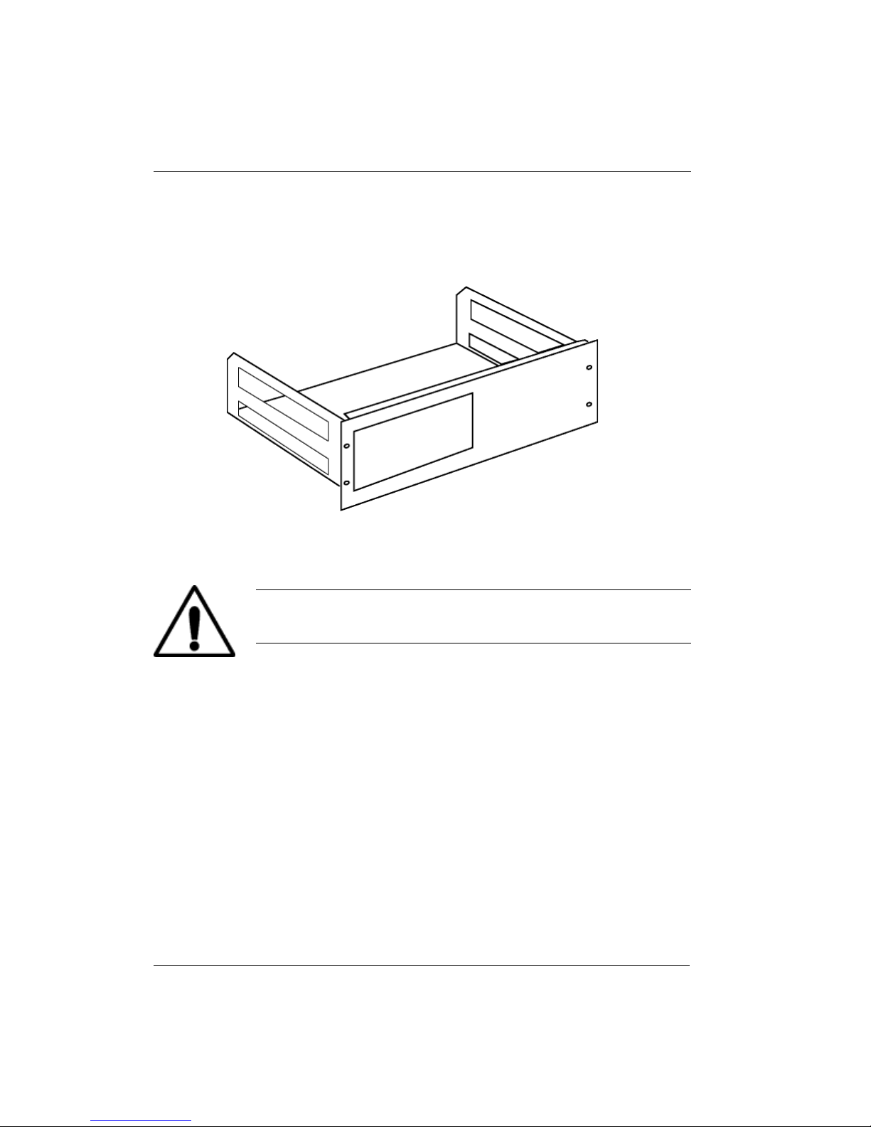
Figure 1: 4122-030 Rack Mount Kit............................................................9
Figure 2: 4034-032 Rack Mount Kit............................................................10
Figure 3: Model 24C Rear Panel Layout.................................................... 37
Figure 4: Model 24C Front Panel Layout...................................................41
Figure 5: Thermocouple Module.................................................................95
Figure 6: Thermocouple Switches.............................................................. 95
Figure 7: Proper Assembly of the Input Connector ....................................181
Figure 8: Diode and Resistor Sensor Connections.....................................182
Figure 9: RS-232 Null Modem Cable..........................................................184
v
Page 6

Cryo-con Model 24C
Index of Tables
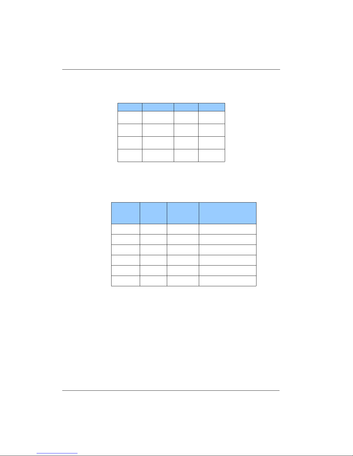
Table 1: Model 24C Instrument Accessories...............................................14
Table 2: Cryogenic Accessories..................................................................15
Table 3: Loop #1 Output Summary.............................................................18
Table 4: Control Type Summary..................................................................19
Table 5: Supported Sensor Types...............................................................21
Table 6: Accuracy and Resolution for PTC Resistors..................................22
Table 7: Minimum and Maximum Resistance vs. Bias Voltage...................23
Table 8: Resolution for NTC Resistors........................................................24
Table 9: 10mV Constant-Voltage Accuracy Specifications..........................24
Table 10: Supported Sensor Configurations...............................................30
Table 11: PTC Resistor Sensor Configuration...........................................31
Table 12: Loop 1 Heater output ranges.......................................................34
Table 13: Loop 2 Heater output ranges.......................................................35
Table 14. AC Power Line Fuses..................................................................38
Table 15: Keypad key functions..................................................................45
Table 16: Temperature Units.......................................................................47
Table 17: Input Channel Configuration Menu..............................................52
Table 18: Control Loop Setup Menus..........................................................55
Table 19: User Configurations Menu..........................................................59
Table 20: System Configuration Menu........................................................ 60
Table 21: Over Temperature Disconnect Configuration..............................62
Table 22: Network Configuration Menu.......................................................64
Table 23: PID Table Edit Menu................................................................... 66
Table 24: Sensor Setup Menu....................................................................67
Table 25: Calibration Curve Menu...............................................................68
Table 26: Auto Tune Menu..........................................................................69
Table 27: digital output Status Indicators....................................................71
Table 28: Digital Output Modes...................................................................71
Table 29: Recommended Sensor Configuration Data.................................78
Table 30: Autotune Menu............................................................................ 83
Table 31: Autotune States...........................................................................84
Table 32: First CalGen Menu, Diode Sensor..............................................92
Table 33: CalGen Menu, 2-point Diode Sensor...........................................93
Table 34: CalGen New Curve Menu...........................................................94
Table 35: Thermocouple Polarities.............................................................97
Table 36: GPIB Host Setup Parameters.....................................................103
Table 37: BB Package Specifications.........................................................164
Table 38: Input Connector Pin-out..............................................................181
Table 39: Sensor Cable Color Codes.........................................................182
Table 40: Loop 1 Connections....................................................................183
Table 41: Loop #2 and Digital Output Connections....................................183
Table 42: RS-232 DB-9 Connector Pinout.................................................184
vi
Page 7

Cryo-con Model 24C Introduction
Introduction
The Model 24C is a four-input, four-control loop cryogenic temperature controller
designed for general purpose laboratory and industrial use. Each input is independent
and capable of temperature measurement to <100mK with an appropriate
temperature sensor. The Model 24C supports virtually any cryogenic temperature
sensor produced by any manufacturer.
The four-output control loop circuits feature a primary 50W heater, a secondary
heater of 25W and two 10-Volt non-powered outputs. All control modes are supported
by all outputs.
The 24C front panel incorporates a large high resolution graphics TFT type Liquid
Crystal Display with an exceptionally wide viewing angle. With it's bright white LED
back-light, complete instrument status can be seen at a glance, even from across the
room.
Sensor Inputs
The Model 24C has four identical input channels, each of which implements a
ratiometric AC resistance bridge. This bridge uses separate, balanced circuits to
simultaneously measure both the voltage drop across the temperature sensor and the
current flowing through it. By measuring current with a higher accuracy than it can be
set, precision resistance measurements are obtained, even at low excitation levels.
Negative-Temperature-Coefficient (NTC) resistors are often used as low temperature
thermometers, especially at ultra-low temperature. Examples include Rutheniumoxide, Carbon-Glass, Cernox™, Carbon-Ceramic, Germanium and several others.
Their resistance and sensitivity increase dramatically at low temperature but their
sensitivity is usually poor at warmer temperatures.
The Model 24C provides robust support for NTC resistor sensors by using constantvoltage AC excitation. In the warm region where the sensor has low resistance and
low sensitivity, constant-voltage will apply a high excitation current to improve
measurement accuracy. At low temperature where the sensor has high sensitivity and
high resistance, measurement errors are dominated by sensor self-heating.
Constant-voltage excitation reduces this error by reducing power dissipated in the
sensor as temperature decreases.
A common source of error at ultra-low temperature is sensor self-heating due to DC
offsets in the measurement electronics. The Model 24C resistance bridge measures
the actual current flowing through the sensor to actively cancel DC offsets by using a
feedback loop to offset it's excitation source.
Ultra-low temperature systems can be negatively affected by coarse steps in
excitation current. The Model 24C prevents this by using a step-less, continuously
variable excitation source.
Positive Temperature Coefficient (PTC) resistor sensors including Platinum, CLTS
and Rhodium-Iron RTDs use the resistance bridge in a constant-current, AC mode.
Platinum RTD sensors use a built-in DIN standard calibration curve that has been
extended to 14K for cryogenic use. Lower temperature use is possible with custom
calibrations.
1
Page 8

Cryo-con Model 24C Introduction
Silicon diode sensors are supported over their full temperature range by using the
bridge in a DC, constant-current mode.
Thermocouple sensors are supported by using an optional thermocouple module
that plugs into any of the Model 24C's input channels. Up to four modules can be
connected to a single instrument.
For all sensor types, conversion of a sensor reading into temperature is performed by
using a Cubic Spline interpolation algorithm. In addition to providing higher accuracy
than conventional linear interpolation, the spline function eliminates discontinuities
during temperature ramps or sweeps by ensuring that the first and second derivatives
are continuous.
Control Loops
There are four independent control loop outputs:
1. Loop #1 heater output is a linear, low noise RFI filtered current source that
can provide up to 1.0 Ampere into 50 resistive loads. Three full-scale
ranges are available in decade increments down to 500mW full-scale.
2. Loop #2 is a linear heater with two output ranges of 25-Watts and 2.5-Watt
full-scale into a 50 load.
3. Loop #3 and #4 are a non-powered analog voltage output intended to control
an external booster power supply. Output is selectable at 10 or 5 Volts full
scale.
User Interface
The Model 24C’s user interface consists of a large, bright TFT type Liquid Crystal
Display and a full 21-key keypad. In this user-friendly interface, all features and
functions of the instrument can be accessed via this simple and intuitive menu driven
interface.
The Home screen projects four user configurable zones that allow the real-time
display of all input channel, control loop and instrument status information. From this
screen, accessing any of
the instrument's
configuration menus
requires only the press of
a single key. As always,
convenient names can be
assigned to input
1A:Sample Holder 2B:First Stage
251.445K 123.845K
300.000K 1-Off-Low 100.000K 2-Off-Low
C:Second Stage D:Rad Shield
15.445K 4.845K
RO-600 RuOx 10mV R500 RuOx 1.0mV
channels.
2
Page 9

Cryo-con Model 24C Introduction
Cryo-con's innovative instrument configuration menus show real-time status
information so the user can instantly view the results of any changes made.
On the control loop menu,
the controlling source
temperature, heater range
and power output level can
be observed while tuning a
loop.
Loop 1A:Sample Holder
Set Pt:300.000K
Pgain: 6.000
Igain: 60.00S
Dgain: 7.500/S
Pman: 5.0000%
Type: RampT
Input: ChA
A: 123.456K
Ramp 42% of Mid
Range: MID
PID Table index: 2
Htr Load: 50W
Next2
An essential feature for
debugging system software
is the Network Configuration
Menu's ability to show
remote commands as they
Network Configuration Menu
Dev: M24C1234
DHCP Ena: On
Msk:255.255.255.0
00:50:C2:6F:40:3C
IP: 192.168.0.198
GWy:192.168.0.1
are sent and received to the
instrument.
>input a:temp?;units?;name?;sys:time?
<0.5321;K;Sample Holder;14:37:25.
Sensor Curves: The Model 24C includes built-in curves that support most
industry standard temperature sensors. Additionally, eight user calibration curves
are available for custom or calibrated sensors. Each user curve may have up to 200
entries and are entered from the front panel, or transferred via any of the available
remote interfaces.
New calibration curves may be generated using the CalGen feature to fit any existing
diode, Platinum or NTC resistor calibration curve at up to three user specified
temperature points. This provides an easy and effective method for obtaining higher
accuracy temperature measurements without expensive sensor calibrations.
Data logging is performed by continuously recording to an internal 1,365 entry
circular buffer. Data is time stamped so that the actual time of an event can be
determined. Non-volatile memory is used so that data will survive a power failure.
Input Channel Statistics: The Model 24C continuously tracks temperature
history independently on each input channel and provides a statistical summary that
indicates the channel's minimum, maximum, average and standard deviation. Also
shown are the slope and the offset of the best-fit straight line of temperature history
data.
Alarms: Visual, remote and audible alarms are independently programmed to
assert, or clear based on high or low temperature condition, or a detected sensor
fault. Latched alarms are asserted on an alarm condition and will remain asserted
until cleared by the user.
3
Page 10

Cryo-con Model 24C Introduction
Relays: The Model 24C has two 10-Ampere dry-contact relays. These can be used
to control a refrigerator system or other external equipment.
Each relay can be asserted or cleared based on the temperature reading of a
selected input channel. High and low setpoints may be set from the front panel or a
remote interface. Furthermore, the relays can be manually asserted ON or OFF.
Remote Control
Standard Remote Interfaces include Ethernet and RS-232. IEEE-488.2(GPIB) and
USB are optional.
The Model 24C connects directly to any Ethernet Local-Area-Network (LAN) to make
measurements easily and economically. TCP/IP and UDP data port servers brings
fast Ethernet connectivity to all common data acquisition software programs including
LabView. An ASCII text based command language identical to those commonly
used with GPIB or RS-232 interfaces is implemented. This is the primary way that
user software interfaces to the instrument.
Using the Ethernet SMTP protocol, the controller will send e-mail based on selected
alarm conditions. E-mail is configured by using the web page interface.
Using the Ethernet HTTP protocol, the instrument’s embedded web server allows the
instrument to be viewed and configured from any web browser.
4
Page 11

Cryo-con Model 24C Introduction
5
Page 12

Cryo-con Model 24C Introduction
In order to eliminate ground-loop and noise pickup problems commonly associated
with IEEE-488 systems, the Model 24C moves the internal IEEE-488 circuitry to an
optional external module that interfaces directly to the electrically isolated and low
noise Ethernet interface. This compact module is completely transparent to the IEEE488 system and does not require changes to customer software or LabView drivers.
Remote Command Language: The Model 24C's remote command language
is SCPI compliant according to the IEEE-488.2 specification. SCPI establishes a
common language and syntax across various types of instruments. It is easy to learn
and easy to read.
The SCPI command language is identical across all Cryo-con products so that the
user's investment in system software is always protected.
Command Scripts can be used to completely configure an instrument including
setting custom sensor calibration curves and PID tables. Further, scripts can query
and test data. They are commonly used in a manufacturing environment to set a
baseline state and test a target product. In the laboratory, scripts can be used to save
and restore configurations for various experiments.
XML (Extensible Markup Language) is used for the structure and format of script files.
XML can be generated and edited with a standard text editor. Further, it is easy to
read and understand.
Firmware updates: Instrument firmware updates may be installed by using the
Ethernet connection. Cryo-con provides firmware updates, on request, via e-mail.
They are free of charge and generally include enhancements and new features as
well as problem fixes. Send e-mail to cctechsupport@cryocon.com
Ethernet API: An Applications Program Interface (API) package is supplied that
facilitates communication with the instrument using the TCP/IP and UDP protocols. It
is supplied as a Microsoft Windows DLL that is easily linked with C, C++ or Basic
programs.
6
Page 13

Cryo-con Model 24C Preparing the controller for use
Preparing the controller for use
The following steps help you verify that the controller is ready for use.
Supplied Items
Confirm that you have received the following items with your controller. If anything is
missing, contact Cryogenic Control Systems, Inc. directly.
Model 24C Cryogenic Temperature Controller.
This User’s Manual.
Cryo-con software CD.
Input connector kit (4024-016) consisting of four screw-in DIN-6 input
connectors (PN 04-0414).
Output connector kit (4124-018) consisting of a 10-pin detachable
terminal block (04-0007) and a dual banana plug(04-0433).
Detachable 120VAC USA Line Cord (04-0310), or universal Euro cord.
Certificate of Calibration.
Verify the AC Power Line Voltage Selection
The AC power line voltage is set to the proper value for your country when the
controller is shipped from the factory. Change the voltage setting if it is not correct.
The settings are: 100, 120 220, or 240 VAC. For 230 VAC operation, use the 240 VAC
setting.
On the rear panel of the instrument, the AC voltage selection is on the power entry
module. If the setting is incorrect, please refer to section Fuse Replacement and
Voltage Selection to change it.
7
Page 14
Cryo-con Model 24C Preparing the controller for use
Status: Self Test
Apply Power to the Controller
Connect the power cord and turn the controller on by pressing the Power key for a
minimum of 2 Seconds. The front panel will show a Power Up display with the model
number and firmware
revision.
While the Power Up display
is shown, the controller is
performing a self-test
procedure that verifies the
proper function of internal
data and program
memories, remote interfaces and input/output channels. If an error is detected during
this process, the controller will freeze operation with an error message display. In this
case, turn the unit off and refer to Appendix C: Troubleshooting Guide.
Caution: Do not remove the instrument’s cover or attempt to repair
the controller. There are no user serviceable parts, jumpers or
switches inside the unit. Further, there are no software ROM chips,
trim pots, batteries or battery-backed memories.
All firmware installation and instrument calibration functions are
performed externally via the remote interfaces.
Cryogenic Control Systems, Inc.
Model 24C SN:209999 Rev: 1.23B
IP:192.168.1.5 Static Port: 5000
MAC: 00:50:c2:6f:40:3E
Calibration: Testing NVRAM: Testing
Device Name: NewCryocon Connecting
GPIB Adrs: 012 RS232: 9600
After about fifteen seconds, the self-test will complete and the controller will begin
normal operation.
8
Page 15

Cryo-con Model 24C Preparing the controller for use
Installation
General
The Model 24C can be used as a bench top instrument, or mounted in an equipment
rack. In either case, it is important to ensure that adequate ventilation is provided.
Cooling airflow enters through the side holes and exhausts out the fan on the rear
panel. It is important to allow at least ½" of clearance on the left and right sides and to
ensure that the exhaust path of the fan is not blocked.
Rack Mounting
You can rack mount the controller in a standard 19-inch rack cabinet using the
optional rack mount kit. Instructions and mounting hardware are included with the kit.
4122-030 Single instrument 2U rack mount kit.
4034-032 Single instrument shelf rack mount kit.
4034-031 Dual instrument shelf rack mount kit.
Figure 1: 4122-030 Rack Mount Kit
9
Page 16
Cryo-con Model 24C Preparing the controller for use
Using the one- or two-instrument shelf rack mount kit, additional equipment may be
mounted on the shelf space next to the controller. Note that these rack mount kits
extends the height of the controller from 2U (3½") to 3U (5¼").
Since the controller is an industry standard size, it is possible to mount any similar
size instrument next to it in the rack.
Figure 2: 4034-032 Rack Mount Kit
10
Warning: When using the shelf type rack mount kits, do not use
screws that protrude into the bottom of instrument more than ¼".
Otherwise, they can touch internal circuitry and damage it.
Page 17

Cryo-con Model 24C Preparing the controller for use
Initial Setup and Configuration
Before attempting to control temperature, the following instrument parameters should
be checked:
1. The Loop #1Heater resistance setting should match the actual heater
resistance that you are going to use. Choices are 50 and 25. A heater
resistance of less than 25 should use the 25 setting. Using the 50
setting with a heater resistance much less than 50 may cause the
instrument to overheat and disengage the control loops.
Set the heater resistance by pressing the Loop 1 key and refer to the Loop
Configuration Menu section.
2. The Loop #1 heater range should be set to a range where the maximum
output power will not damage the equipment. To set this parameter, press the
Loop 1 key and refer to the Loop Configuration Menu section.
3. The controller has an over-temperature disconnect feature that monitors a
selected input and will disconnect both control loops if the specified
temperature is exceeded. This feature should be enabled in order to protect
your equipment from being over heated. To enable, press the System key
and refer to the System Functions Menu section.
i NOTE: Factory defaults may be restored at any time by use of
the following sequence: 1) Turn AC power OFF. 2) Press and hold
the Enter key while turning power back ON. This sequence will
restore factory defaults including resetting user supplied sensor
calibration curves and saved user configurations. However, it will
NOT erase the instrument’s internal calibration data.
11
Page 18
Cryo-con Model 24C Preparing the controller for use
Model Identification
The model number of all Cryo-con controllers is identified on the front and rear panel
of the instrument as well as in various instrument displays.
Ordering Information
Standard Description
Model 24C
Controller with four standard multi-function sensor input channels.
Controller includes: User's Manual, Cryo-con software CD, four
input connectors, heater connector, terminal block plug, detachable
power cord and a certificate of calibration.
Specify AC Line Voltage when ordering:
-100 Configured for 90 - 100VAC with detachable USA power
cord.
-110 Configured for 110 - 120VAC with detachable USA power
cord.
-220 Configured for 220VAC with detachable universal Euro
(Shuko) line cord.
-240 Configured for 240VAC with detachable universal Euro
(Shuko) line cord.
Options Description
4039-004
4001-002
4001-001
Thermocouple Input Module. Field installable. Supports all
thermocouple types. Controller supports up to 4 modules.
IEEE-488.2 (GPIB) Option. Field installable.
USB Option. Serial Port Emulation. Field installable.
12
Page 19

Cryo-con Model 24C Preparing the controller for use
Technical Assistance
Troubleshooting guides and user’s manuals are available on our web page at
http://www.cryocon.com.
Technical assistance may be also be obtained by contacting Cryo-con as follows:
Cryogenic Control Systems, Inc.
PO Box 7012
Rancho Santa Fe, CA 92067-7012
Telephone: (858) 756-3900x100 FAX: (858) 759-3515
e-mail: cctechsupport@cryocon.com
For updates to LabView™ drivers, Cryo-con utility software and product
documentation, go to our web site and select the Download area.
Current Firmware Revision Level
As of July, 2014 the firmware
revision level for the Model 24C
series is 2.52. Instrument firmware
can be updated in the field via the
LAN port. Updates are available on
the Internet.
Current Hardware Revision Level
As of July, 2014, the hardware
revision level for the Model 24C
Hardware
Revision
Relay contact
rating
Non-powered
outputs
Loop 2 output
A B, C
2.0A, 30W 10.0A, 150W
10.0V
10W or 1.0W-
Volt full-scale
Selectable 10V or 5V
full scale.
25W or 2.5W-Volt full-
scale
series is C.
Returning Equipment
If an instrument must be returned to Cryo-con for repair or recalibration, a Return
Material Authorization (RMA) number must first be obtained from the factory. This
may be done by Telephone, FAX or e-mail.
When requesting an RMA, please provide the following information:
1. Instrument model and serial number.
2. User contact information.
3. Return shipping address.
4. If the return is for service, please provide a description of the malfunction.
If possible, the original packing material should be retained for reshipment. If not
available, consult factory for packing assistance.
Cryo-con’s shipping address is:
Cryogenic Control Systems, Inc.
17279 La Brisa
Rancho Santa Fe, CA 92067-7012
13
Page 20
Cryo-con Model 24C Preparing the controller for use
Instrument Accessories
Cryo-con Part # Description
4034-031
4034-032 One instrument shelf rack mount kit
4034-035
04-0310
04-0317 AC Power Cord, Cont. European (Shuko)
04-0414
04-0007 Ten-pin detachable terminal block for Loop 2 and relay connections.
04-0433
4042-040 8' Sensor cable, four wire, wired to DIN-6 connector.
3124-029
Two instrument shelf rack mount kit
Shielded IEEE-488.2 Interface Bus Cable, 6'6"
AC Power Cord
Din-6 Sensor Input Connector, Amphenol T3400 001
Dual banana plug for Loop 1 connection.
Additional User’s Manual/CD
Table 1: Model 24C Instrument Accessories
14
Page 21
Cryo-con Model 24C Preparing the controller for use
Cryogenic Accessories
Cryo-con Part # Description
S900
S900 series Silicon diode Temperature Sensors. Temperature
range: 1.4 to 500K
Cryo-con R400 Ruthenium-Oxide temperature sensor.
R400
Temperature range: 2.0K to 273K. Optimized for use in Liquid
Helium systems including superconducting magnets.
R500
Cryo-con R500 Ultra-low temperature Ruthenium-Oxide
temperature sensor. Temperature range: <100mK to 40K.
CP-100
GP-100
XP-100
XP-1K
3039-002
3039-001
4039-011
4039-012
3039-006
CP-100 series Ceramic Wound RTD, 100
GP-100 series Glass Wound RTD, 100
XP-100 series Thin Film Platinum RTD, 100
XP-1K series Thin Film Platinum RTD, 1,000
Cartridge Heater, Silicon free, 25 / 25 Watt,
1/4" x 1 1/8". Temperature range to 1,600K
Cartridge Heater, Silicon free, 50 / 50 Watt,
1/4" x 1 1/8. Temperature range to 1,600K
Pre-cut Nichrome wire heater w/connectors, 25
Pre-cut Nichrome wire heater w/connectors, 50
Bulk Nichrome Heater Wire, 32AWG,
Polyamide insulation, 100’
Table 2: Cryogenic Accessories
15
Page 22

Page 23

Cryo-con Model 24C A Quick Start Guide to the User Interface.
A Quick Start Guide to the User Interface.
Pressing the Power key will toggle the controller's AC power on and off. This key
must be pressed and held for two seconds before power will toggle.
Pressing the Stop key will immediately disengage both control loops. Pressing the
Control key will engage them.
Use the ESC key to exit an erroneous entry.
Home Status Display
Pressing the Home key will return the screen to the Home Display from anywhere in
the sub-menus. The Home Display is the primary display for instrument status
information.
The Home Status display consists of four zone quadrants. Each zone has 4 lines,
containing 20 characters each, and can be individually configured to show useful
information with minimum clutter.
To configure zone displays, press the Display key.
Accessing the heater setpoint
To instantly access the setpoint for either control loop, press the Set Pt key.
Configuring a temperature sensor
Configuring an input sensor from the front panel is performed by using the Input
Channel Configuration Menu. First, press input channel key ChA , ChB , ChC , or
ChD to select the desired channel for configuration.
The first line of the Input Channel Configuration menu is used to change the sensor
units. It shows the selected input channel, the current
temperature (in real time) and the current units. An
example is shown here.
To change the sensor units, use the + and 0 keys to scroll through the available
options. When the desired units are shown, press the Enter key to make the
selection. The display will now show the current temperature with the new units.
Next, go to the sensor selection field by pressing the down arrow navigation key. This
field is used to select the actual sensor type. In the example shown below, the input
channel is currently configured for a standard Cryo-con S900 diode sensor. Use the +
and 0 keys to scroll through the available sensors including user sensors. When the
desired sensor is shown, press the Enter key to make the selection. A complete
listing of selectable sensors is given in Appendix A.
Before one of the user-supplied sensors can be
used, the sensor’s calibration curve and configuration data must be installed. This is
best done by using Cryo-con’s utility software.
This completes the process of configuring an input channel. Press the Home key to
return to the Home Status display.
+ --
+Sen: 1 Cryocon S900
17
Page 24
Cryo-con Model 24C A Quick Start Guide to the User Interface.
+
Configuring the Control Loops
Before using the Loop #1 (main heater) control output, it is essential that the proper
load resistance and output range be selected. This is done using the Control Loop
Setup menu as follows:
Press the Loop 1 key.
In the Control Loop Configuration menu, Use the up, down, right and left
keys to scroll to the Htr Resistance field. An example is shown here:
Use the + and 0 keys to select between a 50-
Ohm and a 25-Ohm heater and then press
the Enter key.
Use the navigation keys to scroll to the Range
+
field and then select the desired heater range.
Be sure to select a range that does not exceed the ratings of your cryostat. A
summary of full-scale output power for the various ranges is given here:
Range
Hi
Mid
Low
Max. Output Power
25 50
25 Watts 50 Watts
2.5 Watts 5.0 Watts
0.25 Watts 0.50 Watts
Table 3: Loop #1 Output Summary
Next, the control type should be set by scrolling to the Type field and selecting the
desired loop operating mode.
+
18
Page 25
Cryo-con Model 24C A Quick Start Guide to the User Interface.
A summary of control types is given here:
Type Description
Off
Control loop is disabled.
Manual control mode. Here, a constant heater output power is
Man
applied. The Pman field selects the output power as a percentage of
full-scale.
Table
PID
RampP
RampT
PID control mode where the PID coefficients are generated from a
stored, user supplied PID table.
Standard PID control.
Temperature ramp control. Uses PID control to perform a
temperature ramp.
Temperature ramp control using a PID table. Uses PID control to
perform a temperature ramp.
Table 4: Control Type Summary
Caution: The Model 24C has an automatic control-on-power-up
feature. If enabled, the controller will automatically begin controlling
temperature whenever AC power is applied. For a complete
description of this function, please see the Auto Ctl function in the
System Functions menu section.
Restoring Factory Defaults
Factory default settings may be restored with the following simple procedure:
1. Turn AC power OFF by pressing the Power key.
2. Press and hold the Enter key while turning AC power back ON. Keep the
key pressed until you see the power-up display indicating that defaults
have been restored.
i NOTE: Factory defaults may be restored at any time by use of
the following sequence: 1) Turn AC power OFF. 2) Press and hold
the Enter key while turning power back ON. This sequence will
restore factory defaults including resetting user supplied sensor
calibration curves and saved user configurations. However, it will
NOT erase the instrument’s internal calibration data.
19
Page 26

Page 27
Cryo-con Model 24C Specifications, Features and Functions
Specifications, Features and Functions
Specification Summary
User Interface
Display Type: 40 character by 8 line TFT LCD with LED backlight.
Number of Inputs Displayed: Four.
Keypad: Sealed Silicon Rubber.
Temperature Display: Six significant digits, autoranged.
Display Update Rate: 0.5 Seconds.
Display Units: K, C, F or native sensor units.
Display Resolution: User selectable to seven significant digits.
Input Channels
There are four input channels, each of which may be independently configured
for any of the supported sensor types.
Sensor Connection: 4-wire differential. Screw-in type DIN-6 circular.
Connections are described in the Sensor Connections section.
Supported Sensors Include:
Type Excitation
Silicon diode
Platinum RTD
Cernox™ Constant-Voltage AC 100mK to 420K Lakeshore, all types
Ruthenium-Oxide
Carbon-Ceramic
Rhodium-Iron Constant-Current, 1mA AC 1.4 to 800K Oxford PHZ 0002
Germanium
Thermistor
Silicon
Thermistor
Thermistor
CLTS Constant-current, 100uA AC 4 to 325K Vishay CLTS-2B
Thermocouple
Constant-Current, 1mA AC 14 to 1200K
10mA DC
Constant-Voltage AC 100mK to 273K SI RO-600, SI RO-105
Constant-Voltage AC 1.0K to 300K TMi-A1
Constant-Voltage AC 100mK to 100K AdSem, Inc.
Constant-Voltage AC 1.0K to 400K AdSem, Inc.
Constant-Voltage AC 193 - 523K Measurement Specialties
None 1.4 to 1500K All thermocouple type
Temperature
Range
1.4 to 475K
Example
Cryo-con S900
SI-440, 430, 410
Lakeshore DT-670, 470
Cryo-con CP-100
Cryo-con GP-100
Cryo-con XP-100
Cryo-con XP-1K
Table 5: Supported Sensor Types
21
Page 28

Cryo-con Model 24C Specifications, Features and Functions
Sensor Selection: Front Panel or remote interface. There are no internal
jumpers or switches.
Sample Rate: 15Hz per channel in all measurement modes.
Digital Resolution: 24 bits.
Measurement Filter: 0.5, 1, 2, 4, 8, 16, 32 and 64 Seconds.
Calibration Curves: Built-in curves for industry standard sensors plus eight
user curves with up to 200 entries each. Interpolation is performed using a
Cubic Spline.
CalGen: Calibration curve generator fits any diode or resistor sensor curve at
1, 2 or 3 user specified temperature points.
Sensor Performance Specifications:
Diode Sensors
Configuration: Constant-Current mode, 10mA ± 0.05% DC excitation.
Note: Current source error has negligible effect on measurement accuracy.
Input voltage range: 0 to 2.00VDC.
Accuracy: ±(80mV + 0.005% * reading)
Resolution: 2.3mV
Drift: 25ppm/ºC over an ambient temperature range of 25ºC± 5ºC.
PTC Resistor Sensors
Configuration: Constant-Current AC resistance bridge mode.
Ratiometric measurement cancels any error in excitation current.
Drift: 20ppm/ºC over an ambient temperature range of 25ºC± 5ºC.
AC Excitation Frequency: 7.5Hz bipolar square wave.
22
Range
PTC100
1mA
PTC1K
100mA
Max/Min
Resistance
500W
0.01W
7.5KW
0.1W
Table 6: Accuracy and Resolution for PTC Resistors
Excitation
Current
1.0mA
100mA 1.0mW
Resolution Accuracy
0.1mW
± (0.004 + 0.01%)Ω
± (0.05 + 0.02%)Ω
Note: The Model 24C is calibrated with AC excitation. User
selection of DC excitation will introduce offset errors in temperature
measurement.
Page 29

Cryo-con Model 24C Specifications, Features and Functions
Thermocouple Sensors
Thermocouple devices are supported by using an optional external module.
Measurement Drift: 25ppm/ºC Input Range: ±70mV
Accuracy: ±1.0µ V ± 0.05%. Resolution: 0.0003%
Installed Types: K, E, T and Chromel-AuFe (0.07%).
Input Connector: Isothermal, Screw-type terminals.
NTC Resistor Sensors
Type: Constant-Voltage AC resistance bridge with excitations
of 10mV, 3.0mV, 1.0mV and 300µV RMS. Fixed or auto-ranged.
Excitation Current: 2.5mA to 10nA.
Four ranges of 2.5mA, 250uA and 25uA full-scale.
Excitation Frequency: 7.5Hz bipolar square wave.
Drift: >10W and <10KW: 15ppm/ºC
<10W or >10KW: 25ppm/ºC
over an ambient temperature range of 25ºC± 5ºC.
DC Offset Current: <8nA by active cancellation.
Resistance Range: 0.5W to 1.0MW.
Resistance 10mV 3.0mV 1.0mV 300µV
Maximum
Minimum
Table 7: Minimum and Maximum Resistance vs. Bias Voltage
1.0MW 100KW 100KW 33KW
1W 0.5W 0.5W 0.16W
23
Page 30
Cryo-con Model 24C Specifications, Features and Functions
Resolution: Shown below are typical RMS resistance noise values measured
at 50% of full-scale on a room-temperature resistor with a 3-Second analog
time-constant.
Range 10mV 3.0mV 1.0mV
40W
400W
4KW
40KW
Table 8: Resolution for NTC Resistors
1.0mA
255µW
100μA
2.6mW
10μA
26mW
1.0μA
250mW
1.0mA
255µW
100μA
2.6mW
10μA
26mW
1.0μA
250mW
100μA
2.6mW
10μA
26mW
1.0μA
260mW
1.0μA
2.5W
Accuracy: Accuracy for the 10mV bias setting is specified in ranges
according to the following table. The formulas apply from the maximum to the
minimum resistance shown below.
Resistance
Range
1Ω
4Ω
40Ω
400Ω
4KΩ
100KΩ
Excitation
Current
Range
1.0mA 1 - 4Ω ±0.02Ω ± 0.05% * Rdg
1.0mA 4 - 40Ω ±0.02Ω ± 0.05% * Rdg
100µA 40 - 400Ω ±0.2Ω ± 0.05% * Rdg
10µA 400 - 4KΩ ±2.0Ω ± 0.05% * Rdg
10µA 4K - 40KΩ ±20Ω ± 0.05% * Rdg
10µA 40K - 100KΩ ±50Ω ± 0.1% * Rdg
Min/Max
Resistance
Accuracy at 25C
Table 9: 10mV Constant-Voltage Accuracy Specifications
While it is possible to measure resistance above100KΩ, accuracy is not
guaranteed.
The 1.0mV and lower bias settings are provided for use in very low
temperature applications (<~1K) where errors are often dominated by sensor
self heating rather than the accuracy of resistance measurement. In the
1.0mV range, the Model 24C will have an accuracy of ± 0.5% over the
resistance range of 40 to 10.0KΩ.
24
Page 31

Cryo-con Model 24C Specifications, Features and Functions
Control Outputs
Number of Loops: Four.
Control Input: Either sensor input.
Loop Update Rate: 15Hz per loop.
Control Type: PID table, PID, Ramp or Manual.
Autotune: Minimum bandwidth PID loop design.
PID Tables: Six user PID tables available for storage of Setpoint vs. PID and
heater range. Up to 16 entries/table.
Setpoint Accuracy: Six+ significant digits.
Fault Monitors: Control loops are disconnected upon detection of a control
sensor fault or excessive internal temperature.
Over Temperature Disconnect: Heater may be relay disconnected from
user equipment when a specified temperature is exceeded on any selected
input.
Loop #1 Primary Heater Output
Type: Short circuit protected linear current source. Maximum compliance is
selectable at 25V or 50V.
Ranges: Three output ranges of 1.0A, 0.33A and 0.10A full-scale, which
correspond to 50W, 5.0W and 0.5W when used with a 50 load.
Load Resistance: 25 or 50 for maximum output.
Minimum Load: 10 in 25 setting, 40 in 50 setting.
Digital Resolution: 1.0PPM of full-scale, corresponding to 20 bits.
Readback: Heater output power, Heatsink temperature.
Connector: Dual Banana-plug.
Loop #2 Heater Output
Type: Short circuit protected linear current source. Compliance is 36V.
Ranges: 25W or 2.5W full-scale into a 50 load.
Load Resistance: 50 for maximum output.
Digital Resolution: 1.0PPM of full-scale, corresponding to 20 bits.
Readback: Heater output power.
Connector: 10-pin detachable terminal block.
Status Outputs
Audible and Visual Alarms: Independent audible and visual alarms.
Status reported via Remote Interface: Heater over temperature fault.
Loop #3 and #4 Outputs
Type: 0 - 10 or 0 - 5 Volt analog output. All control modes available.
Maximum Output Current: 20mA.
Connector: 10-pin detachable terminal block.
25
Page 32

Cryo-con Model 24C Specifications, Features and Functions
Relay Outputs
Number: 2
Type: Dry-contact.
Contact Rating: 10A @125 VAC, 5A @250 VAC or 5A @30 VDC for
resistive loads.
Function: Asserted or cleared based on temperature setpoint data.
Deadband: User defined.
Connector: 10-pin detachable terminal block.
Remote Interfaces
Remote interfaces are electrically isolated to prevent ground loops.
Ethernet: Supported protocols include: HTTP, TCP/IP, UDP and SMTP.
Electrically isolated.
RS-232: Serial port is an RS-232 standard null modem. Rates are 9600,
19,200, 38,400, 557,600 and 115,200 Baud.
IEEE-488 (GPIB): External option. Full IEEE-488.2 compliant.
USB 2.0: External option. Serial port emulator.
Language: Remote interface language is IEEE-488.2 SCPI compliant.
Further, it is identical within the entire Cryo-con instrument line.
Compatibility:
National Instruments LabView™ drivers available for all interfaces.
Ethernet API available for C++ and Basic.
User Setups
Four User Setups are available that save and restore the complete
configuration of the instrument.
General
Ambient Temperature: 25
o
C 5 oC for specified accuracy.
Mechanical: 8.5"W x 3.5"H x 12"D. One half-width 2U rack. Instrument bail
standard, rack mount kit optional.
Weight: 9 Lbs.
Enclosure: Aluminum. Machined Aluminum front panel.
Power Requirement: 100, 120, 220 or 240VAC +5% -10%.
50 or 60Hz, 150VA max.
26
Page 33

Cryo-con Model 24C Specifications, Features and Functions
MAT
MAV
0.002604
MAV 60 10
6
5 10
5
1.36317
M A T
MA V
SenSen
MAV 60 10
6
5 10
5
SenRdg
Performance Summary
Measurement Accuracy
Diode Sensors
The formulas for computing measurement accuracy while using diode sensors are:
Where:
MAV is the electronic Measurement Accuracy in Volts
MAT is the Measurement Accuracy in Kelvin
SenRdg is the sensor reading in Volts at the desired temperature.
SenSen is the sensor sensitivity in Volts / Kelvin at the desired temperature.
For example, to calculate the measurement accuracy of the Model 24C using a Cryocon S900 sensor at 10K, look up the sensor reading and sensitivity in the S900 data
table in Appendix G. At 10K, SenRdg is 1.36317 Volts and SenSen is 0.002604
Volts/Kelvin . Therefore,
and
The result is MAV = 128V and MAT = 49mK.
27
Page 34

Cryo-con Model 24C Specifications, Features and Functions
MA T
MA R
SenSen
MA T
M A R
SenSen
M A R 5.0 10
5
SenVal5.0 10
5
Range
M A R 0.002 1.0 10
4
SenVal
PTC Resistor Sensors (RTDs)
The formulas for PTC resistor sensor in the PTC100 range are:
Where:
MAR is the electronic Measurement Accuracy in Ohms
MAT is the Measurement Accuracy in Kelvin
SenVal is the sensor reading in Ohms at the desired temperature.
SenSen is the sensor sensitivity in Ohms / Kelvin at the desired temperature.
To calculate the measurement accuracy of the Model 24C using a 100W Platinum
RTD in the PTC100 range with the sensor at 77.35K, look up the sensor reading and
sensitivity in Appendix G. The appendix shows that SenRdg is 20.38W and SenSen is
0.423 W/Kelvin. Therefore, the computed values show that MAR = 0.004038W and
MAT = 9.5mK.
For ranges other than PTC100, please refer to the PTC Specifications table.
NTC Resistor Sensors
The formulas for NTC resistor sensors are:
Where:
MAR is the electronic Measurement Accuracy in Ohms
Range is the resistance range in Ohms (100, 1K or 10K)
MAT is the Measurement Accuracy in Kelvin
SenVal is the sensor reading in Ohms at the desired temperature.
SenSen is the sensor sensitivity in Ohms / Kelvin at the desired temperature.
To calculate the measurement accuracy of the Model 24C using a Cryo-con R500
Ruthenium-Oxide sensor in the 1KW range with the sensor at 1.0K, look up the
sensor reading and sensitivity in Appendix G. SenVal is 2327W and SenSen is
-1203W/Kelvin. Therefore the computed values equal MAR = 0.17W and MAT =
100K.
28
Page 35

Cryo-con Model 24C Specifications, Features and Functions
MRT
MR
SenSen
MR FullScale 2
20
Measurement Resolution and Control Stability
The input analog-to-digital converter used by the Model 24C is 24 bits with no missing
codes. Thus, the measurement resolution is identifiable as one part in 2
-24
. However,
the only use for measurement resolution is to compute control stability. Since control
stability is limited by the output DAC rather than the input, the measurement
resolution specification is limited to one part in 2
-20
.
Where:
MR is the electronic measurement resolution in sensor units.
FullScale is the full scale range
MRT is the measurement resolution in temperature units.
SenSen is the sensor sensitivity at the measurement point.
29
Page 36

Cryo-con Model 24C Specifications, Features and Functions
Input Channel Characteristics
There are four independent, multi-purpose input channels; each of which can
separately be configured for use with any supported sensor.
Input Configurations
A complete list of the sensor types supported by the Model 24C is shown below:
Sensor Type
Diode 2.25V CI 10µA DC Silicon diode, GaAs diode.
ACR
PTC100
PTC1K
CLTS
TC70 ±70mV None 0
None 0 None 0 Disable Input Channel
Max. Voltage/
Resistance
10 to 1.0M
0.5 - 500
5 - 5.0K
300
Bias types are:
CI – Bridge maintains a constant current through the sensor.
CV – Bridge maintains a constant voltage-drop across the sensor.
Bias
Type
CV
CI 1.0mA AC
CI 100uA AC
CI 100uA AC CLTS
Table 10: Supported Sensor Configurations
Excitation
Current
2.5mA - 10nA ACNTC resistors including Ruthenium
Oxide, Cernox™
100 Platinum, Rhodium-Iron
1,000 Platinum
All thermocouple types. (requires
Thermocouple option)
Typical Use
i Note: Any disconnected inputs to the Model 24C should be set
to type 'None'. This will turn the input off.
Silicon Diode Sensors
Silicon diode sensors (2-volt diodes) are configured with a 10mA current source
excitation and a 2.25 Volt input voltage range.
Gallium-Arsenide Diode Sensors
Gallium-Arsenide diodes or 6-Volt diodes are sometimes used in systems where
magnetic fields are present. Use is limited to operation above about 30K with fields of
less than 5T. The Model 24C supports these sensors down to 25K. If your
requirements are for lower temperature operation, Ruthenium-Oxide is a better
choice.
Gallium-Arsenide sensors do not fit standard calibration curves, therefore, the user
must provide a sensor-specific curve before using this type of sensor.
30
Page 37

Cryo-con Model 24C Specifications, Features and Functions
Cryogenic Linear Temperature Sensor (CLTS)
Supported by use of a 100uA constant-current AC resistance bridge. A standard
calibration curve for the Vishay CLTS-2B sensor is available on the utility CD.
Maximum resistance is 1.2K and minimum is 10. Sensor type is PTC1K.
PTC Resistor Sensor (RTDs)
The Model 24C supports all types of Positive-Temperature-Coefficient (PTC) resistive
sensors using a constant-current AC or DC resistance bridge technique.
Standard calibration curves are provided for DIN43760 and IEC751 Platinum sensors.
These curves have been extended down to 14K. Below that, the sensors can be used
with user supplied calibration curves.
A table of recommended setups for various types of PTC resistor sensors is shown
here:
Type Measurement Range Sensor Excitation
Platinum, 100 1.0K - 0.01
Platinum, 1000 10K - 0.1 100mA, AC
Rhodium-Iron
Table 11: PTC Resistor Sensor Configuration
1.0K - 0.01
1.0mA, AC
1.0mA, AC
When AC excitation is On, the sensor excitation current is a 10 Hz square wave. This
square wave excitation generates a small noise signal in the sensor cable, which can
be picked up by sensitive measurement equipment in the system. Turning AC
excitation Off will eliminate this noise at the cost of introducing a thermal EMF DC
offset voltage into the sensor measurement.
31
Page 38

Cryo-con Model 24C Specifications, Features and Functions
sen so r
bi as
d
R
V
P2
NTC Resistor Sensors
The Model 24C supports almost all types of Negative-Temperature-Coefficient (NTC)
resistive sensors by using a constant-voltage AC resistance bridge technique, these
sensors can be used down to very low temperatures. Examples of NTC resistor
sensors include: Ruthenium Oxide, Cernox™, Carbon Glass, Germanium and other
thermistors.
Constant-voltage excitation is necessary since the resistance thermometers used
below about 10K exhibit a negative temperature coefficient. Therefore, a constantvoltage measurement reduces the power dissipation in the sensor as temperature
decreases. By maintaining low power levels, sensor self-heating errors that occur at
very low temperatures are minimized.
In the constant-voltage mode, sensor excitation is a 7.5Hz bipolar square-wave.
For more information on using the Model 24C with NTC resistor sensors, please refer
to the section titled "Voltage Bias Selection".
Power dissipation in the sensor is computed by:
The actual power being dissipated in the sensor may be viewed in real-time by going
to the Input Configuration Menu. An asterisk (*) character next to the temperature
display indicates that the resistance bridge is not balanced at the proper voltage bias.
When used with high resistances, measurement accuracy steadily degrades due to
the extremely low excitation current required. The trade-off in measurement accuracy
vs. sensor excitation current is taken for two reasons:
1. The sensitivity of NTC resistor sensors is extremely high in the low
temperature end of their range. Therefore the reduced measurement
accuracy does not degrade temperature measurement accuracy.
2. The low current settings are required since sensor self-heating at low
temperature is a very significant source of errors.
Calibration tables for NTC sensors may be entered either directly in Ohms or in (base
10) Log of Ohms to accommodate the generally logarithmic nature of their calibration
curves.
32
Page 39

Cryo-con Model 24C Specifications, Features and Functions
CalGen Calibration Curve Generator
The CalGen feature generates new calibration curves for Silicon diode, thermocouple
or Platinum sensors. This provides a method for obtaining higher accuracy
temperature measurements without expensive sensor calibrations.
Curves can be generated from any user-selected curve and are written to a specified
internal user calibration curve area.
The CalGen function may be performed in the instrument by using the front panel.
Alternatively, the feature is also implemented in the Cryo-con utilities software.
Input Channel Statistics
Input temperature statistics are continuously maintained on each input channel. This
data may be viewed in real time on the Input Channel menu, or accessed via any of
the remote I/O ports.
Statistics are:
Minimum Temperature.
Maximum Temperature.
Temperature Variance.
Slope and Offset of the best-fit straight line to temperature history.
Accumulation Time
The temperature history may be cleared using a reset command provided.
Electrical Isolation and Input Protection
The input channel measurement circuitry is electrically isolated from other internal
circuits. However, the common mode voltage between an input sensor connection
and the instrument's ground should not exceed 40V.
Sensor inputs and outputs are provided with protection circuits. The differential
voltage between sensor inputs should not exceed 15V.
33
Page 40

Cryo-con Model 24C Specifications, Features and Functions
Control Loop Outputs
Control Loop #1, Primary Heater Output
The Loop #1 heater output is a short circuit protected linear current source. This
output is heavily regulated and RFI filtered. External filters should not be necessary.
Automatic shutdown circuitry is provided that will protect the heater output stage from
excessive temperature. Here, the heater output will be turned off until the output
stage returns to its safe operating area, then the output will be returned to normal
operation.
Load resistance values of either 25 or 50 may be selected. Using a 25 load, the
heater will be automatically configured to have a compliance voltage of 25V. With a
50 load, the compliance voltage is 50V. In either case, the maximum output current
is 1.0A.
Range
High
Medium
Low
Compliance Voltage
25 50
25V 50V 1.0A 25 Watts 50 Watts
25V 50V 0.333A 2.5 Watts 5.0 Watts
25V 50V 0.100A 0.25 Watts 0.50 Watts
Table 12: Loop 1 Heater output ranges.
Full-Scale
Current
Take care to ensure that the proper load resistance is selected. Connection to a 25
load while a 50 is selected will result in overheating and eventual automatic heater
shutdown. Conversely, connection to a 50 load while setting a 25 load will result in
the dissipation of only one half of the indicated heater power in the load.
Load resistance and Full Scale Output Range are selected via the front panel, or any
of the remote interfaces.
Heater output power displays are based on the heater read-back circuitry which
measures output current independently of the actual heater circuitry. Thus, heater
fault conditions are detected and their corresponding alarms asserted.
Max. Output Power
25 50
i Note: Heater output displays are given as a percentage of
output power, not output current. In order to compute actual output
power, multiply this percentage by the full-scale power of the
selected range. However, to compute actual output current, you
must first take the square root of the percentage and then multiply
by the full-scale current.
34
Page 41

Cryo-con Model 24C Specifications, Features and Functions
Control Loop #2, Secondary Heater Output
Control loop #2 is a constant current source similar to Loop #1.
Range Compliance Full-Scale Current Max. Output Power
High
Low
36V 0.71A 25 Watts
36V 0.22A 2.5 Watts
Table 13: Loop 2 Heater output ranges.
Control Types
There are four control types available in the Model 24C. They are Manual, PID, PID
Table, Ramp and Ramp Table. All modes are available on all control loops.
Manual mode operation allows setting the output power manually as a percentage of
full-scale power.
PID control allows feedback control using an enhanced PID algorithm that is
implemented using 32-bit floating point Digital Signal Processing techniques.
Enhancements include:
1. Noise filtering on the derivative term. The D term will provide better
control stability, but is often not used because, without filtering, it makes
the control loop too sensitive to noise.
2. Integrator wind up compensation. While slewing to a new setpoint, the
integrator in the PID loop can build up to a very large value. If no
compensation is applied, overshoot and time to stability at the new
setpoint can be delayed for an extremely long time. This is especially true
in cryogenic environments where process time constants can be very
long.
3. Dithering and filtering the outputs in order to increase output resolution
and improve control stability.
The PID Table control mode is a PID control loop just as described above. However, it
is used to look up PID and heater range values based on the specified setpoint. This
is useful where a process must operate over a wide range temperature range since
optimum PID values usually change with temperature.
To use the Table mode effectively, the user must first characterize the cryogenic
process over the range of temperature that will be used, then generate PID and
heater range values for various temperature zones. This is usually done using the
autotune capability. Once the information is placed into a PID Table, the Model 24C
will control in Table mode by interpolating optimum PID values based on setpoint.
The Model 24C allows for the entry of six independent PID Tables. Each table may
contain up to 16 temperature zones.
In the Ramp control mode, the controller approaches a new setpoint at a user
specified rate. When this setpoint is reached, the controller will revert to PID control.
35
Page 42

Cryo-con Model 24C Specifications, Features and Functions
Alarm Outputs
Alarm outputs include a LED indicator, an audible alarm, on-screen display and
remote reporting.
Alarms may be asserted based on high temperature, low temperature, input sensor
fault or heater fault conditions.
A user selectable dead-band is applied to all alarms.
The High and Low temperature alarms may be latched. See the Input Channel
Configuration Menu.
i Note: To clear a latched alarm, first press the Alarm key and
then press the Home key.
Relays
The Model 24C has two dry-contact mechanical relay outputs.
Relays are asserted or cleared based on the temperature reading of selected input
channels. Each output has a high and low set-point that may be enabled from the
front panel or a remote interface. Furthermore, relays can be manually asserted ON
or OFF.
Normally-Open contacts are available on the rear panel. Contact rating is 10A @125
VAC, 5A @250 VAC or 5A @30 VDC for resistive loads. Maximum switching power is
150W.
Remote Interfaces
Ethernet LAN and RS-232 interfaces are standard. IEEE-488.2 (GPIB) and USB are
external, field installable options. All functions and read-outs available from the
instrument may be completely controlled by any of these interfaces.
The LAN interface is electrically isolated and is 10/100-BaseT compliant. Connection
is made via the RJ-45 connector on the rear panel.
The Serial port is an RS-232 standard null modem with male DB9 connector. Rates
are 9600, 19,200 and 38,400 Baud.
When installed, the GPIB option is fully IEEE-488.2 compliant. Connection is made at
the rear panel's LAN port.
The programming language used by the Model 24C is identical for all interfaces and
is SCPI language compliant.
36
Page 43

Cryo-con Model 24C Specifications, Features and Functions
Rear Panel
Figure 3: Model 24C Rear Panel Layout
AC Power Connection
The Model 24C requires single-phase AC power of 50 to 60 Hz. Voltages are set by
the line voltage selector in the Power Entry Module on the rear panel. The power cord
will be a standard detachable 3-prong type.
Line voltage selections are: 100, 120, 220 or 240VAC. Tolerance on voltages is +10%
to -5% for specified accuracy and -10% for reduced full-scale heater output in the
highest output range.
The power jack and mating plug of the power cable meet Underwriters Laboratories
(UL) and International Electrotechnical Commission (IEC) safety standards.
User-replaceable fuses are incorporated in the Power Entry Module.
i Note: The Model 24C uses a smart power on/off scheme.
When the power button on the front panel is pressed to turn the
unit off, the instrument's setup is copied to flash memory and
restored on the next power up. If the front panel button is not used
to toggle power to the instrument, the user should configure it and
cycle power from the front panel button one time. This will ensure
that the proper setup is restored when AC power is applied.
Caution: Protective Ground: To minimize shock hazard, the
instrument is equipped with a three-conductor AC power cable. Plug
the power cable into an approved three-contact electrical outlet or
use a three-contact adapter with the grounding wire (green) firmly
connected to an electrical ground (safety ground) at the power outlet.
37
Page 44

Cryo-con Model 24C Specifications, Features and Functions
Fuse Replacement and Voltage Selection
Access to the Model 24C's fuses and voltage selector switch is made by using a
screwdriver to open fuse drawer in the power entry module. A slot is provided above
the voltage selector window for this purpose.
The fuse and voltage selection drawer cannot be opened while the AC power cord is
connected.
Voltage selection is performed by rotating the selector cams until the desired voltage
shows through the window shown.
There are two fuses that may be removed by pulling out the fuse modules below the
voltage selector. Fuses are specified according to the AC power line voltage used.
Line Voltage Fuse Example
100VAC, 120VAC 2.0A slow-blow Littlefuse 313 002
220VAC, 240VAC 1.0A slow-blow Littlefuse 313 001
Table 14. AC Power Line Fuses
Mechanical, Form Factors and Environmental
Enclosure
The Model 24C enclosure is standard 2-U half-width 17-inch rack-mountable type that
may be used either stand-alone or incorporated in an instrument rack.
Dimensions are: 8.5"W x 3.5"H x 12"D. Weight is 9 Lbs.
An instrument bail and feet are standard. Rack Mount kits are available from Cryo-
con for both single instrument or side-by-side dual configurations. A rack mount kit is
optional.
38
Page 45

Cryo-con Model 24C Specifications, Features and Functions
Environmental and Safety Concerns.
Safety
The Model 24C protects the operator and surrounding area from electric shock or
burn, mechanical hazards, excessive temperature, and spread of fire from the
instrument.
Keep Away From Live Circuits: Operating personnel must not remove
instrument covers. There are no internal user serviceable parts or
adjustments. Refer instrument service to qualified maintenance personnel.
Do not replace components with power cable connected. To avoid injuries,
always disconnect power and discharge circuits before touching them.
Cleaning: Do not submerge instrument. Clean exterior only with a damp cloth
and mild detergent.
Grounding: To minimize shock hazard, the instrument is equipped with a
three-conductor AC power cable. Plug the power cable into an approved
three-contact electrical outlet only.
Safety Symbols
39
Page 46

Page 47

Cryo-con Model 24C Front Panel Operation
Front Panel Operation
The user interface of the Model 24C Cryogenic Temperature Controller consists of a
40 character by eight line TFT LCD and a keypad. All features and functions of the
instrument are accessed via this simple and intuitive menu-driven interface.
Figure 4: Model 24C Front Panel Layout
The Keypad
Function Keys
The Function Keys on the Model 24C are Power , Stop , Control , Home , and Enter
. These buttons always perform the same function, regardless of the context of the
display.
The Power key is used to turn AC power to the controller on or off. Note that this key
must be pressed and held for one second in order to toggle AC power.
i Note: The Model 24C uses a smart power on/off scheme.
When the power button on the front panel is pressed to turn the
unit off, the instrument's configuration is copied to flash memory
and restored on the next power up. If the front panel button is not
used to toggle power to the instrument, the user should configure
the controller and cycle power from the front panel button one time.
This will ensure that the proper setup is restored when AC power is
applied.
41
Page 48

Cryo-con Model 24C Front Panel Operation
The Stop and Control keys are used to disengage or engage the instrument’s
output control loops. Pressing Control will immediately turn on all enabled heater
outputs and pressing Stop will turn them both off. To enable or disable an
individual loop, go to the Loop Configuration Menu menu and select the desired
‘Type’.
The Home key is used to take the display to one of the Home Status displays. These
displays show the full status of the instrument.
The Enter key is used to enter numeric data or selections.
The Keypad and Setup Menu Keys
The keypad keys on the far right side of the instrument serve a
dual function. When the display is showing one of the
configuration menus, the keypad is used for navigation and data
entry. When the display is in the Home Status Display, their
function is identified by a label printed just above the key and is
as follows:
ChA, ChB, ChC, ChD - Go to the Input Channel Setup
menu.
Loop 1, Loop 2 - Go to the Control Loop Setup menu.
Auto Tune - Go to the auto-tuning menu for either loop.
Config - Go to the User Configurations menu.
Sensors - Go to the Sensors configuration menu, including sensor calibration
curves.
PID Table - Go to the PID tables setup menu.
System - Go to the System setup menu. This includes fields for Remote Input /
Output, Display filters and the Over Temperature Disconnect feature.
Display - Go to the Display setup menu. This allows configuration of the front
panel display from a list of options
Alarm - Go to the Alarm Status menu.
Set Pt - Set the setpoint values for both control loops.
Options - Go to the Options Setup Menu.
42
Page 49

Cryo-con Model 24C Front Panel Operation
Keypad Data Entry
The keypad is used to enter data and make selections in the various configuration
menus. Fields require the entry of numeric or enumeration data.
Enumeration fields are display fields where the value is one of several specific
choices. For instance, the Heater Range field in the Loop 1 setup menu may contain
one of only three possible values: HIGH, MID and LOW. There are many enumeration
fields that contain only the values ON and OFF.
Enumeration Fields
An enumeration is always indicated by the + character in the first column of the field.
To edit an enumeration field, place the cursor at the desired field by using the
Navigation keys. Then, use the + or 0 keys to scroll through all of the possible
choices in sequence.
When a field has been changed, the cursor will flash over the + symbol. To select the
displayed value, press the Enter key. To cancel selection without updating the field,
press the Esc key.
To select the displayed value, press the Enter key. To cancel selection without
updating the field, press the Esc key. The cursor will then return to the + symbol.
Numeric Data Fields
Numeric data is indicated by a pound-sign (#) in the first column of the field.
The Keypad Keys are used to enter data into numeric fields. These keys are: the
numerals 0 through 9, the period key (.) and the +/- key.
When the cursor is positioned to a field that requires numeric data, the keypad keys
become hot and pressing one of them will result in the field being selected and
numeric entry initiated. This is indicated by a flashing cursor.
When the Enter key is pressed, numeric data in the selected field will be checked for
range and the instrument’s configuration is correspondingly updated.
i Note: If the numeric entry is outside of the required range, an
error is indicated by the display of the previous value of the field.
43
Page 50

Cryo-con Model 24C Front Panel Operation
Once the entry of numeric data has started, it can be aborted by pressing the Home
key. This will cause the field to be de-selected and its value will be unchanged.
Pressing the ESC ( ), key will exit data entry and restore the field to its previous
value. The key can be used as a backspace.
i Note: Up to 20 digits may be entered in a numeric field. When
digit entry has exceeded the display field width, additional
characters will cause the display to scroll from right to left. When
entry is complete, the updated display field may not show all of the
digits entered because of limited field width, however, the digits are
retained to the full precision of the controller's internal 32 bit
floating point format.
44
Page 51

Cryo-con Model 24C Front Panel Operation
Summary of keypad functions
Key Function Description
Power
Stop
Control
Enter
Home
ChA
Esc
Sensors
System
. Display
± Setpoint
0 Alarm
1 ChB
2 ChC
3 ChD
4 Options
5 Loop 1
6 Loop 2
7 Sensors
8 PID Table
9 Auto Tune
Toggle power. Must be held in for two seconds.
Disengage all control loops.
Engage all control loops.
Enter key
Go to the Home Status Display.
Input Channel Menu for Channel A. / Scroll Display UP
If in data entry mode, Escape. Additionally, if the keypad has been
locked by a remote interface, pressing this key will unlock it and clear
the Remote LED / Scroll Display DOWN.
Go to the sensor setup menu / Scroll Display RIGHT
If in data entry mode, backspace. From home display, go to the
System setup menu / Scroll Display RIGHT.
Go to the display configuration menu.
Change the setpoint value for either control loop. / Scroll to NEXT
selection.
Go to the Alarm Status menu. / Scroll to PREVIOUS selection
Input Channel Menu for Channel B.
Input Channel Menu for Channel C.
Input Channel Menu for Channel D.
Options Setup Menu. Loop 3 and 4 setup menus.
Go to the Loop 1 setup menu.
Go to the Loop 2 setup menu.
Sensor data and calibration curve menu.
PID table menu.
Autotune menu.
Table 15: Keypad key functions.
The LED indicators and Audible Alarm
There are three LED indicators located just below the main display.
The blue Control LED is illuminated whenever either of the control loops are
engaged and actively controlling temperature. To disengage the loops, press the
Stop key.
The red Alarm LED is illuminated whenever a user programmed alarm has been
triggered. To clear the alarm, the enabled event that is asserting the alarm must be
disabled. Press the Alarm key to view the status of all alarms.
The green Remote LED can be turned on or off under program control by the remote
interface. Use of this LED by a computer connected to the instrument is optional. This
LED may also indicate that the keypad is locked out. To clear the LED and the
keypad lockout, press the Esc key.
45
Page 52

Cryo-con Model 24C Front Panel Operation
The Front Panel Display
Home Status Displays
At the top of the instrument’s menu tree are the home status displays. They can be
selected from anywhere in
the instrument’s menu tree
by pressing the Home
key.
The Home display is easily
configured to show only
desired data. There are
four zones, each of which
may be independently configured.
Pressing the Display key will list the configuration of each zone.
To change the contents of
a zone, scroll to the
desired zone and press
the Enter key. This will
result in a display of all
possible selections for the
selected zone. A summary
of the important selections
is given below:
Temperature
Displays an input channel temperature in 2x font. Above the temperature is the input
channel indicator, name string and alarm status. Below is the sensor type and
excitation level.
Loop Status Displays
These displays show the current status of a selected control loop. The control loop's
input temperature is shown in 2x font. Above is the loop and channel indicator, the
input channel's name string and alarm status. Below in 1x font is the loop's setpoint,
heater range and percent-of-full-scale output power.
1A Sample Holder 2B First Stage
251.445K 296.845K
300.000K 1-Off-Low 100.000K 2-Off-Low
C: Second Stage D:Rad Shield
251.445K 296.845K
RO-600 RuOx 10uV R500 RuOx 1.0mV
Home Zone Configuration Menu
Zone 1 Loop 1 Status
Zone 2 Loop 2 Status
Zone 3 ChC Temperature
Zone 4 ChD Temperature
Input Channel Statistics Display
The Channel A, B, C and D statistics displays show the selected input channel
temperature, the slope of the temperature history, the minimum and maximum
temperatures.
The slope of the temperature history (M) is given in Display Units per Minute.
When any of the statistics pages are displayed, pressing the Enter key will reset the
accumulation.
46
Page 53

Cryo-con Model 24C Front Panel Operation
Temperature Displays
A typical Input Channel Temperature Display is shown on this page. It consists of the
input channel designator, a Temperature reading and the current temperature units.
The temperature, a seven-character field, is affected by the Display Resolution setting
in the System menu. This setting may be 1, 2, 3 or Full. Settings of 1, 2, or 3 indicate
the number of digits to the right of the decimal point to display whereas the Full
setting causes the display to be left justified in order to show the maximum number of
significant digits possible.
The Display Resolution setting does not affect the internal accuracy of arithmetic
operations. It is generally used to eliminate the
display of unnecessary digits that are beyond the
sensor’s actual resolution.
If the Input Channel has been disabled, a blank
display is shown.
Temperature units are selected in the individual
input channel setup menus, ChA , ChB , ChC or
ChD. Temperature Units may be K, C or F.
When Sensor Units (S) is selected, the raw input
K Kelvin
C Celsius
F Fahrenheit
Ohms
V Volts
Table 16: Temperature Units
readings are exhibited. These will be in Volts or
Ohms.
Sensor Fault Display
A sensor fault condition is identified by a temperature display of seven dash (-)
characters as shown here. The sensor is open, disconnected
or shorted.
Temperature Out of Range Display
If a temperature reading is within the measurement range of the instrument but is not
within the specified Sensor Calibration Curve, a display of
seven dot (.) characters is shown.
i Note: In some cases, there will be an erratic temperature
display when no sensor is connected. This is not an error condition.
The high input impedance of the controller’s input preamplifier
causes erratic voltage values when left unconnected. If an input is
left unconnected, the sensor type should be set to type "None",
which turns the input off.
47
Page 54

Cryo-con Model 24C Front Panel Operation
Loop Status Displays
When the Model 24C is not controlling temperature, the status of the Loop output is
shown.
The first character of the Loop Status Display is always the loop number, which will be
either a superscripted 1 or 2 corresponding to Loop 1 or Loop 2.
The Loop number is accompanied by the heater status as follows:
1. -OFF- Indicates that heater output is
functional and the control loop is off or
1
disabled.
For the primary heater, Loop 1, the range is also shown. Range settings may
be either Hi, Mid, Low or Min. The range is set in the Loop 1 menu.
For the secondary output, or Loop 2, the range will be shown as Hi or Low.
The range is set in the Loop 2 menu.
2. Overtemp indicates that the controller’s Internal Temperature Monitor circuit
shut off the heater. This fault is usually the result of a shorted heater or use of
a heater with significantly less resistance than the selected load resistance.
After the controller has been allowed to cool to an acceptable temperature,
pressing the CONTROL button will clear the
1
error and restore control mode.
3. OTDisconn indicates that the heater output was disconnected by the Over
Temperature Disconnect Monitor. This monitor is configured by the user and
functions to disable the heater if a specified over temperature condition
exists on a selected input channel. See the
System menu for information on how to
1
configure and use this important feature.
If the Model 24C is controlling temperature (loop ON), the heater status display shows
the loop output as a percentage of full scale.
This example shows the Heater Status for Loop 2 in a Model 24C controller. The unit
is in control mode and is outputting 30% of full scale
output current. This means that the output power is
2HI
(30%)^2, or 9% of 25 Watts.
48
Page 55

Cryo-con Model 24C Front Panel Operation
Loop Bar Chart Display
The Loop Bar Chart is a 50-segment bar chart that shows the measured output of a
selected loop output.
The bar is composed of ten blocks with five segments. Therefore, output current can
be read to an accuracy of 2%.
Note that the bar chart does not have a loop number indicator.
Some examples are:
Loop ON, zero output:
Loop OFF:
Loop ON, 50% output:
i Note: The Model 24C uses an independent circuit to read
current actually flowing through the load. The heater bar graph
shows this measured current. If the unit is controlling temperature,
but the bar graph indicates zero current flow, an error condition
exists, possibly an open heater.
49
Page 56

Page 57

Cryo-con Model 24C Front Panel Menu Operation
Front Panel Menu Operation
Instrument Setup Menus
To access the various instrument setup menus, press one of the Setup Menu keys.
The display must be in ‘Home Status’ in order for these keys to be active.
The user may exit a Setup Menu and return to the Home Status display at any time by
pressing the Home key.
Menus contain several lines, so scroll through the display using the Navigation keys.
The last character of each line in a setup menu is the format indicator. The indicator
will be blank until the cursor is moved to the line.
Format indicators are:
# - Numeric entry.
+ - Enumeration entry using the + and 0 keys.
- The line is selected by pressing the Select key.
The Setpoint Menu
The setpoint menu is accessed by pressing the Set Pt key. This gives one-key
access to the setpoints for all of the control loops.
Press the Home key to exit the menu without update.
The Alarm Status Display Menu
The current status of the temperature alarms may be viewed by pressing the Alarm
key.
Alarms are set for each input channel using the Input Channel Setup menu described
below.
When an alarm is asserted, the Alarm LED on the front panel will light. Pressing the
Alarm key will display all of the alarms. Status is shown as follows:
— No alarm
LO Low temperature alarm
HI High temperature alarm
The letter L at the end of the line indicates that the alarm is latched. A latched alarm is
asserted when the alarm condition is set. It stays asserted until it is manually cleared
by the user.
i Note: To clear a latched alarm, first press the Alarm key to view
the alarms and then press the Home key to clear the latch and return
to the Home display.
51
Page 58

Cryo-con Model 24C Front Panel Menu Operation
Input Channel Configuration Menu
These menus contain all of the user-configurable parameters for a selected sensor
input channel.
Use the navigation keys to
move around the list.
When the cursor (+) is
located to the left of the
ChA indicator, channels B,
C and D may be displayed
by pressing the + key. To
ChA:Sample Holder
High Alarm:100.00
+ 1.543K -- High Alarm Enable:No
Low Alarm: 10.00
Sen:32 RO-600 Low Alarm Enable:No
Input Config Deadband: 0.25
CalGen Latched Enable:No
Statistics Audible Enable:No
sequence in the reverse
direction, press the 0 key.
Input Channel Configuration Menu
Input channel units. Selections are K, C, F or S.
+ 1.543K --
1
+
2
Input Config.
3
CalGen
4
Statistics
5
6
+
7
8
+
9
Deadband: 0.250
10
+
11
+
12
Here, S selects primitive sensor units. When S is
selected, the actual sensor units of Volts or Ohms
will be displayed.
Sensor type selection. Allows selection of any
user or factory installed sensor. The 20 shown
indicates that the current sensor is number 20.
Go to the input configuration menu.
Go to the CalGen screen.
Go to the input channel statistics screen.
Setpoint for the High Temperature alarm. Use the
keypad for numeric entry and then press the
Enter key.
High temperature alarm enable. Selections are
Yes or No.
Setpoint for the Low Temperature alarm.
Enables latching alarms on the selected input
channel.
Alarm dead-band.
Enables the internal audio alarm to sound on any
enabled alarm condition.
Enables or disables latching alarm conditions. A
latched alarm is cleared by pressing the Alarm
key followed by Home key.
52
Table 17: Input Channel Configuration Menu
Page 59

Cryo-con Model 24C Front Panel Menu Operation
Temperature Units Enumeration, Default: K
The Temperature Units field (line 1) assigns the units used to display temperature for
the input channel. Options are K for Kelvin, C for Celsius, F for Fahrenheit and S for
sensor units. Note that if the S option is selected, the actual sensor units will be
displayed when the field is deselected. Available sensor units are V for Volts and for
Ohms.
Use the + or 0 key to scroll through all of the options. When the desired units are
displayed, press the Enter key to make the selection. The display will now show the
current temperature with the new units.
Sensor Type Selection Enumeration
Line 2 selects the Sensor type for the input channel. When this field is selected, the
scroll keys are used to scroll through all of the available sensor types. Factory
installed sensors appear first and then user sensors. For a list of both factory and
user sensors, refer to Appendix A.
New user sensor types and calibration curves are added using the Sensors menu.
Setting a Temperature Alarm
The Alarm lines are used to setup alarm conditions. The Model 24C allows alarm
conditions to be assigned independently to any of the input channels.
High temperature and low temperature alarms may be entered and enabled. Note
that a user selected dead-band is applied to the assertion of high and low
temperature alarms.
Alarm conditions are indicated on the front panel by the Alarm LED and various
display fields. They are also reported via the remote interfaces.
When the audible alarm is enabled, a high-pitched buzzer will sound when an alarm
condition is asserted.
The Model 24C supports latched alarms. These are alarms that remain asserted even
after the condition that caused the alarm has been cleared. To clear a latched alarm,
first press Alarm to view the Alarm Status Display and then press the Home key to
clear.
Input Channel Statistics
The Model 24C continuously tracks temperature history on each input channel. The
Input Statistics shown in this menu provides a summary of that history.
The channel history is reset whenever the channel is initialized and can also be reset
by pressing the Enter key while the cursor is on any of the statistics lines.
The Accum line shows the length of time that the channel history has been
accumulating. It is in units of Minutes.
The Minimum and Maximum temperature lines show the temperatures from during
the accumulation time. Values are shown in the currently selected display units.
S2 is the temperature variance, which is computed as standard deviation squared.
The M and b fields display the slope and the offset of the LMS best-fit straight line to
the temperature history data.
53
Page 60

Cryo-con Model 24C Front Panel Menu Operation
CalGen Sub-menu
Selection of the CalGen field initiates the calibration curve generator feature. This
feature is described in the section Using CalGen.
Setting a Temperature Alarm
The Alarm lines are used to setup alarm conditions. The Model 24C allows alarm
conditions to be assigned independently to any of the input channels.
High temperature and low temperature alarms may be entered and enabled. Note
that there is a 0.25K hysteresis in the assertion of high and low temperature alarms.
Alarm conditions are indicated on the front panel by the Alarm LED and various
display fields. They are also reported via the remote interfaces.
When the audible alarm is enabled, a high-pitched buzzer will sound when an alarm
condition is asserted.
The Model 24C supports latched alarms. These are alarms that remain asserted even
after the condition that caused the alarm has been cleared. To clear a latched alarm,
first press Alarm to view the Alarm Status Display and then press the Home key to
clear.
Loop Configuration Menu
These menus contain all of the user-configurable parameters for the selected control
loop.
The Loop 1 menu is used to
perform the setup of the
primary 25/50 Watt heater
output. This display was
designed to provide all of the
information required to tune
heater parameters and is
Loop 1A:Sample Holder
Set Pt:300.000K
Pgain: 5.0000
Igain: 60.000S
Dgain: 7.5000/S
Pman: 5.0000%
Type: Man
Input: ChA
A: 1.234K
1-Off-Low -Htr-Off
Range: LOW
PID Table index: 1
Htr Load: 50W
Next
rather complex.
Loop #1 and #2 menus can be accessed directly from the front panel. Loop #3 and #4
can be accessed by first pressing the Options key.
When the cursor is on the top line, the user can scroll through all of the control loop
menus by pressing the + or
0 keys.
Loop 3D:Booster Supply
Set Pt:300.000K
Pgain: 5.0000
Igain: 60.000S
Dgain: 7.5000/S
Pman: 5.0000%
Type: Man
Input: ChD
D: 211.234K
3-Off-Low -Htr-Off
Range: 10VDC
PID Table index: 1
Htr Load: N/A
Next
54
Page 61
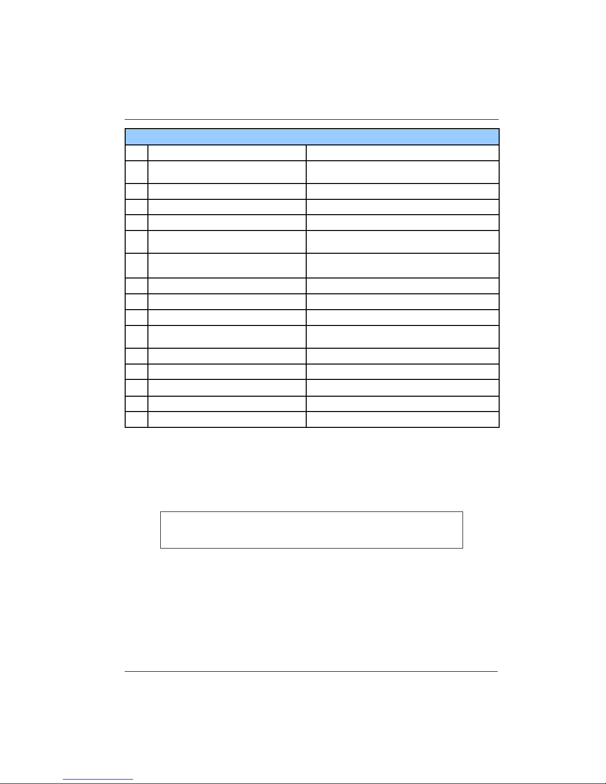
Cryo-con Model 24C Front Panel Menu Operation
Loop Configuration Menu
Set Pt:300.000K
1
A: 299.99K
2
1-Off-LOW -Htr-Off-
3
4
5
6
7
+
8
+
9
+
10
11
12
13
14
+
15
Next
16
Numeric setpoint entry.
Indicator of the controlling input channel and it's
current temperature.
Status indicator for the control loop.
Proportional gain, or P term for PID control.
Integrator gain term, in Seconds, for PID control.
Derivative gain term, in inverse-Seconds, for PID
control.
Output power, as a percent of full scale, when
controlling in the Manual mode.
Control input channel, ChA , ChB, ChC or ChD.
Output power range.
Control Type
Power limit as a percent of full scale. On loop 1, this
limit only applies to the HI range.
Maximum value allowed for the setpoint on this loop.
Table number for control in Table mode.
Sets the heater load resistance.
Ramp rate in temperature units per minute.
Go to the next page of the control loop setup menu.
Table 18: Control Loop Setup Menus.
Setpoint Numeric Entry
In the first line of this menu the user can change the setpoint, while still viewing the
temperature of the controlling source channel. This allows the user to view the
temperature without leaving the setup menu.
i Note: Entry of a setpoint can be overridden by the Maximum
Setpoint field described below. The instrument will not accept an
entry that exceeds the maximum.
Control loop setpoints may also be entered by using the Set Pt key.
Control Loop PID values Numeric Entry
The Pgain, Igain and Dgain lines correspond to the Proportional, Integral and
Derivative coefficients of the control loop. Pman is the output power that will be
applied to the load if the manual control mode is selected.
Values for the Proportional, or P, gain term range from zero to 1000. This is a unitless gain term that is applied to the control loop. Gain is scaled to reflect the actual
heater range and the load resistance.
55
Page 62

Cryo-con Model 24C Front Panel Menu Operation
Integrator gain values range from zero to 10,000. The units of this term are Seconds.
A value of zero turns the integration function off.
Derivative gain values have units of inverse Seconds and may have values from zero
to 1000. A value of zero turns the Derivative control function off.
The Pman field is only used when the heater output is in manual control mode. The
value is represented in percent of full-scale output power (Watts) and may have
values from zero to 100%.
i Note: The Model 24C expresses heater output values in terms
of percent of full-scale output power. The actual power, in Watts,
applied to the load is proportional to the square-root of output
current.
Control Source Input Channel Enumeration
The input filed selects the control loop source input. Any input channel may be
selected.
Control Loop Range Enumeration, Default: Low
The Range field selects the full-scale output for the selected control loop.
56
Page 63

Cryo-con Model 24C Front Panel Menu Operation
Control Types Enumeration, Default: Man
The Type filed selects the actual control algorithm used for the selected loop.
Loop control modes are:
1. Man for Manual control mode. Here, a constant heater output power is
applied when the unit is controlling temperature. The Pman field selects
the output as a percentage of full-scale.
2. Table. This is a PID control mode where the PID coefficients are
generated from a stored PID table based on setpoint.
3. PID for standard PID control.
4. Off. In this mode, the controller will not apply power on this output
channel. Note that the Model 24C is a dual-loop controller. The Off
control mode is used if regulation is desired only on the other channel.
5. RampP. This is a temperature ramp mode. When a ramp operation is
complete, the controller will revert to standard PID mode control at the
final setpoint.
6. RampT. This is a temperature ramp mode that uses the PID tables to
generate tuning parameters.
For more information on control algorithms, refer to the Heater Control Types table
above.
For more information on temperature ramps, refer to the section on Temperature
Ramping below.
Output Power Limit Numeric entry, Default: 100%
The Power Limit field defines the maximum output power that the controller is allowed
to output. It is a percent of the maximum allowed output. Maximum value is 100% and
minimum is 15%.
The Power Limit is applied to the HI range only.
i Note: Output Power Limit is an important cryostat protection
feature. The user is encouraged to apply it.
Maximum Setpoint Numeric Entry, Default: 1000K
The Maximum Setpoint field is used to prevent the casual user from inadvertently
entering a temperature that might damage the cryostat.
Maximum value is 10,000K and minimum is 0 K.
Setpoint values use the temperature units selected for the controlling input channel.
See the section on Temperature Displays.
i Note: The Maximum Setpoint selection is an important cryostat
protection feature. The user is encouraged to apply it.
PID Table Index Numeric entry, Default: 0
The PID Table index line is used to identify the number of the user supplied PID Table
that will be used when the Table control mode is selected. The Model 24C will store
up to six PID Tables. They are numbered zero through five.
57
Page 64

Cryo-con Model 24C Front Panel Menu Operation
Heater Resistance Enumeration, Default: 25
The heater resistance field is an enumeration that sets the value of the heater load
resistance. Choices are 50 and 25. When 50 is selected, the heater will output a
maximum of 50 Volts at 1.0 Ampere or 50 Watts. When 25 Ohms is selected, the
maximum heater voltage is 25 Volts and the output power is 25 Watts.
For additional information, please refer to the Loop 1 Heater output ranges or the
Loop 2 Output Ranges tables.
Warning: It is necessary to set the Load resistance field to the actual
value of the heater load resistance being used. If an incorrect value is
selected, output power indications will be incorrect non-linear heater
operation may result. If the actual heater resistance is less than
selected, the heater may overheat resulting in an automatic over
temperature shutdown.
Ramping Rate Numeric entry, Default: 0.10/min
When performing a temperature ramp, the Ramp field defines the ramp rate. Units
are display units per minute. In the default case, this means Kelvin per minute.
For more information on temperature ramps, refer to the section on Temperature
Ramping.
58
Page 65

Cryo-con Model 24C Front Panel Menu Operation
User Configurations Menu
The User Configurations Menu is displayed by pressing the Config key. It is used to
save or restore up to four instrument setups. Each setup saves the entire state of the
Model 24C including setpoints, heater configurations, input channel data etc.
User Configurations Menu
1
ecall
2
Table 19: User Configurations Menu
Pressing the Enter key saves the instrument setup to
the selected configuration number.
Pressing the Enter key restores a saved
configuration.
Saving a User Configuration
In the Config menu, navigate to the Save field of the desired configuration. Press the
Enter key to execute the save.
Restoring a User Configuration
First, press the Config key and navigate to the Recall field of the desired
configuration. Press the Enter key to execute the restore.
59
Page 66

Cryo-con Model 24C Front Panel Menu Operation
The System Configuration Menu
This menu is accessed by pressing the System key from the Home Status Display. It
is used to set many of the
instrument’s parameters
including display resolution,
I/O port settings etc.
System Configuration Menu
Display TC: 4S
Display Res: 3
Network Config
RS232: 9600
GPIB Adrs: 12
Datalog Config
Over Temp Config
FW Rev: 1.00A
Pwr Up In Ctl: No
AC Line: 60Hz
Date: 08/01/2009
Time: 12:12:42
System Configuration Menu
+Display TC: 4S
1
+Display Res: 3
2
Sets the display time constant in seconds. Selections
range from 0.5S to 64S
Sets the resolution. Selections are: 1, 2, 3 or Full.
Network Config
3
+
4
+GPIB Adrs 12
5
Datalog Config
6
7 Over Temp Config
FW Rev:1.01A
8
+Pwr Up In Ctl:
9
+AC Line: 60Hz
10
Table 20: System Configuration Menu
Press Enter to go to the network configuration menu.
Sets RS-232 port baud rate
Sets GPIB I/O address. (Note: GPIB is an external
option)
Press Enter to go to the data logging setup screen.
Press Enter to go to the Over Temperature Disconnect
configuration screen.
Displays the firmware revision level and hardware
revision letter.
Power Up Mode. Off for normal operation. On to engage
the control loops 10 seconds after power has been
turned on.
AC line frequency. Select 50 or 60Hz.
60
Page 67

Cryo-con Model 24C Front Panel Menu Operation
Display Time Constant Enumeration, Default: 2 Seconds
The Display TC field is used to set the display time-constant. This is an enumeration
field that sets the time constant used for all temperature displays. Choices are 0.5,
1.0, 2.0, 4.0, 8.0, 16.0, 32.0 and 64 Seconds.
The time-constant selected is applied to all channels and is used to smooth data in
noisy environments. The filtering only applies to displayed data; it is not used by the
control loops.
Display Resolution Enumeration, Default: 3
The Display Resolution line (Display Res) is used to set the temperature resolution of
the front panel display. Settings of 1, 2 or 3 will fix the number of digits to the right of
the decimal point to the specified value. A setting of FULL will left-justify the display to
show maximum resolution possible.
Note that the Display Resolution setting only formats the display as a user
convenience. The internal resolution of the Model 24C is not affected by this setting.
Synchronous Filter Configuration Numeric Entry Default: 7
The Synchronous Filter is used to subtract synchronous noise from the input channel.
An example of synchronous noise is the thermal signature of a cryocooler.
The default value of 7 taps is used for a line-frequency synchronous cryocooler.
Values go from 1 (off) to 25 taps with 25 corresponding to 2.5 seconds of filtering.
This is an advanced setup function. Unless you are familiar with the synchronous
noise source that you are trying to remove, leave this field at its default value of 7.
When the number of taps is changed, the control loops will have to be re-tuned
because this filter affects the PID values.
AC Line Frequency Selection Enumeration, Default: 60Hz
Select the AC power line frequency. Choices are 50 or 60 Hz. This function only
affects the operation of the Synchronous Filter described above.
61
Page 68

Cryo-con Model 24C Front Panel Menu Operation
Power-up in Control Mode. Default: Off
The Auto Ctl: field sets the power up mode of the controller’s loops. Choose ‘Off’ for
normal operation where the control loops are engaged by pressing the Control key
and disengaged by pressing the Stop key. When on, the controller will power up, then
after ten seconds, will automatically engage the control loops.
Caution: When enabled, the Power-Up in Control mode feature
causes the controller to engage the control loops automatically
whenever AC power is applied. Please exercise caution in the use of
this feature.
Over Temperature Disconnect Configuration
Navigate to the OTD Configuration menu by pressing the System key and then
selecting the Over Temp Config field.
The Over Temperature Disconnect (OTD) feature monitors a selected input channel
for an over temperature condition. If this exists, all heaters outputs are disconnected
and the Loop Status indicator is set to "OTDisconn". A mechanical relay is used for
the disconnect so that the load is protected, even if the condition was caused by a
fault in the controller’s output circuitry.
The OTD must first be configured to monitor one of the input channels. Note that the
OTD feature is completely independent of control loop function and may monitor any
input.
Next, an OTD Setpoint must be specified. This is the temperature at which an over
temperature shut down is asserted. Temperature units are taken from the source
input channel.
Finally, the OTD function must be enabled.
Important: The Over Temperature Disconnect is an important
cryostat protection feature. The user is encouraged to apply it.
Over Temperature Disconnect Configuration
+
1
+
2
#
3
Table 21: Over Temperature Disconnect Configuration
62
Sets the Over Temperature Disconnect enable.
Selections are On or Off.
Sets the Over Temperature Disconnect source
input channel. Selections are ChA or ChB.
Sets the Over Temperature Disconnect setpoint
temperature.
Page 69
Cryo-con Model 24C Front Panel Menu Operation
Data Logging Configuration Menu
i Note: This section applies only to the internal data logging
feature of the Model 24C. Remote data logging is also supported
by the Cryo-con Utility Software program.
The Data Logging Configuration menu is used to start, stop and configure the data
logging process. This menu is accessed from the System Menu.
The only user configurable
parameter is the Interval in
units of seconds. Once this
is set, data logging starts
when the State is ON and
DataLogging Configuration Menu
+State: ON
#Interval: 5 Sec
Count: 562
Last Log: 8/1/2010 13:15:09
Press Enter to delete data log buffer
stops when the state is OFF.
The last line of the field can
be used to clear the buffer.
The data logging function records all four input temperatures along with a real-time
clock stamp.
The log buffer is circular and contains 1365 entries. Then the maximum number of
entries is exceeded, the oldest samples are written over. The buffer is maintained in
Non-Volatile memory and will therefore survive a power failure.
DataLogging Configuration Menu
+State: ON
#Interval:5 Sec
Count:1365
Last Log: 8/1/2010 12:59:50
Turns logging ON and OFF.
Sets the Data Logging interval in units of
Seconds. Minimum is 1 and maximum is
99,999.
Number of records in the log buffer.
Date / time stamp of last record recorded.
Press Enter to delete data log buffer
Logged data is read via any of the remote interfaces as follows:
Hyperterminal: Enter the command DLOG?. Note: you should setup a Receive
File to store the data before executing this command because a large volume
of data is returned.
Cryocon Utility Software: Click on the Upload Internal Datalog button. This
will enable reading the log buffer to a spreadsheet .csv file.
Note: Reading a full log buffer takes about six minutes on any of the remote
interfaces.
63
Page 70

Cryo-con Model 24C Front Panel Menu Operation
Network Configuration Menu
Navigate to this menu by pressing the System key and selecting the Network Config
field.
Network Configuration Menu
M24C1234
1
1
2
3
4
#Port: 5000
5
00:50:C2:6F:40:3F
6
Instrument name reported over the LAN. May be
modified by using the embedded web page.
Network IP address. Numeric entry. Factory default
is 192.168.1.5.
Network subnet mask. Numeric entry. Default is
255.255.255.0
Network gateway. Only used if the instrument is to
be connected through a gateway to the Internet.
Default is 192.168.0.1.
TCP/IP port assignment. Default is 5000. The UDP
port assignment is always the TCP/IP port plus 1
(Default: 5001).
Media Access Control (MAC) address. Unique for
each instrument.
+DHCP Ena: OFF
6
8
9
Table 22: Network Configuration Menu
Enable DHCP IP address assignment.
Remote I/O: Last command received.
Remote I/O: Last response.
Local Area Network Setup
Setup of the Local Area Network requires a device name, an IP address, a subnet
mask and a gateway.
The device name is any 15 character string. It is reported on the display, but can only
be changed via a remote command. The name is used by LAN systems that have
name servers. In this case, the instrument can be addressed by it's name rather than
it's IP address.
The IP address uniquely identifies the instrument on the LAN. The factory default is
192.168.1.5. While any address can be entered, addresses usually begin with
192.168 which is a Class C network. Other addresses are used only when the
instrument is directly connected to the Internet.
The subnet mask is used to divide the LAN addresses into segments. The default
subnet mask is 255.255.255.0.
A gateway IP address need only be entered if the instrument communicates with the
Internet via a gateway. The factory default gateway is 192.168.0.1, which is used in
systems with Internet Connection Sharing.
64
Page 71

Cryo-con Model 24C Front Panel Menu Operation
PID Tables Menu
The Model 24C can store six user generated PID tables. Each table may have up to
sixteen setpoint zones.
Each setpoint zone in a table requires the entry of a setpoint along with corresponding
values for P, I, D and full-scale heater range.
When controlling in the Table mode, the Model 24C will derive control loop PID
coefficients and heater range by interpolation of the PID Table zones based on that
zone’s setpoint.
PID Tables can be used with both control loops.
Building a table from the front panel requires the entry of several numeric values. For
this reason, the user may want to consider using one of the remote interfaces.
The start, and top level, of this process is the PID Tables menu. Two menu screens
below this are used to enter numeric data. Here is an overview of the process:
1. The PID Tables menu is used to select the PID Table number (zero
through three).
2. Once the table is identified, selecting the EDIT PID TABLE line will take the
menu used to edit individual lines of the selected table.
3. To enter or edit an entry, set the desired entry index and enter the zone
data on the following lines.
4. The last line of this menu is used to save the table when the entire table is
complete.
When a table is saved, it is automatically conditioned so that it can be used directly by
the control loop software. The conditioning deletes all entries with setpoint values of
zero or less and sorts the table based on setpoint. Therefore, an entry may be deleted
by setting the setpoint to any negative number.
65
Page 72

Cryo-con Model 24C Front Panel Menu Operation
The PID Table Menu
The PID Table Menu is accessed by pressing the PID Table key from the Home
Display and then selecting a
table.
The first line of this display
shows which PID table is
being edited. Placing the
cursor on this line will allow
the user to scroll through all
Edit PID Table 01
Table Index: 00
P: 1.60
I: 160.0S
D: 40.0/S
SaveTable&Exit
Setpt: 300.00K
Ch: Default
Range: HI
of the tables.
PID Table Edit Menu
+Table Index
#P
#I:
#D:
#SetPt
+Ch:
+Range:
Sets the line number to edit.
P gain value
I value in units of Seconds.
D value in units of inverse-Seconds.
Setpoint in units of temperature.
Input channel. Can be set to any input or to default where default is the
input channel shown in the loop setup menu.
Heater range setting.
Table 23: PID Table Edit Menu
Pressing the Esc key from this menu will abort the line entry process and return the
display to the PID Table Menu above. Any edits made to the line will be lost.
When a table index is selected, all of the lines on this menu will be updated to show
the selected line. Any data in the selected index will be displayed on the following
lines.
The following data can be entered into the PID zone: Setpoint (SP), Proportional gain
(P), Integral gain (I), Derivative gain (D) and heater range.
To delete a zone from the PID Table, enter zero or a negative number in the setpoint
field. These entries will be rejected when the table is conditioned and stored in Flash
memory.
Save the entire table by scrolling to the last line, SaveTable&Exit, then press the
Enter key.
66
Page 73

Cryo-con Model 24C Front Panel Menu Operation
Sensor Setup Menu
The Sensor Setup menu is used to view and edit user temperature sensor data.
The Sensor Header Edit Menu
Pressing the Sensor key from the Home Status Display accesses the Sensor Setup
Menu. From there, the Sensor Header Edit Menu can be accessed by by scrolling to
the sensor and pressing Enter.
Definition of a sensor requires entering configuration data on this screen followed by
entering a calibration curve.
Sensor Header Edit Menu
+
#
+
Sets the Sensor Type.
Sets the sensor Temperature Coefficient and Calibration
Curve Multiplier.
Sets Units of the sensor’s Calibration Curve. Choices
are: Ohms, Volts and LogOhm.
Table 24: Sensor Setup Menu
The first line on this menu is the sensor table index. Selecting this field allows the
user to scroll through all of the sensors configured in the unit, including user sensors.
The index is displayed along with the sensor name.
Note: the sensor name may be entered via any of the Remote I/O interfaces, but may
not be changed from the front panel.
Sensor Type is an enumeration of all of the basic sensor types supported by the
Model 24C. Choices are shown in the Supported Sensor Configurations table above.
The Multiplier field is a floating-point numeric entry and is used to specify the
sensor's temperature coefficient and to scale the calibration curve. Negative
multipliers imply that the sensor has a negative temperature coefficient. The absolute
value of the multiplier scales the calibration curve. For example, the curve for a
Platinum sensor that has 100 of resistance at 0C may be used with a 1000
sensor by specifying a multiplier of 10.0. Also note that the temperature coefficient
field is only used when the unit is controlling temperature based on the sensor units of
Volts or Ohms.
Units is an enumeration field that identifies the primitive units used by the sensor’s
calibration curve. Choices are Volts, Ohms and LogOhm. LogOhm selects the base
ten logarithm of ohms and is useful with sensors whose resistance vs. temperature
curve is logarithmic.
The Calibration Curve Edit menu
From this screen, the user can input individual entries into a sensor calibration curve.
Note that these curves can have up to 200 points requiring the entry of 400 floating
point numeric values. For lengthy curves, you may want to consider using one of the
remote interfaces. Cryocon provides a free PC utility that uploads or downloads
curves which can be created by a text editor.
67
Page 74

Cryo-con Model 24C Front Panel Menu Operation
The Calibration Curve Edit menu is accessed by pressing the Sensor key, scrolling to
the desired curve and then scrolling to the Edit field of that curve.
The procedure for entering or editing a calibration curve is summarized as follows:
1. First, set the index (IX) field to the curve entry that you want to enter. This
will cause the display of data at that index.
2. Enter data points values by entering numeric data and pressing Enter.
3. Go to the next index by changing the IX field.
4. When all data points have been entered, the SaveCurve&Exit field is
selected to save the curve.
Once complete, the controller will condition the curve by rejecting invalid entries, then
sorting the curve in order of ascending sensor unit values. Therefore, an entry may be
deleted by placing a zero or negative number in the temperature field.
Calibration Curve Menu
Sets the current index to an entry within the current table. Values are
0 to 159. When the Enter key is pressed, the following lines will
display any data corresponding to the selected entry.
Temperature. Units are always in Kelvin.
Sensor reading. Units are taken from the Sensor Setup menu
described above and may be Volts, Ohms or Logohms.
Pressing Enter save entered data and exit the menu. To exit without
saving, press the Home key.
Table 25: Calibration Curve Menu
68
Page 75

Cryo-con Model 24C Front Panel Menu Operation
The Auto Tune Menu
The Model 24C can automatically tune both control loops. For a complete description
of the autotune process including configuration of the tuning menus, refer to the
section titled autotuning.
The autotuning menu entries are shown below:
Auto Tune Menu
+Autotune: Loop 1
#DeltaP: 5%
Mode: PI-
#Timeout: 180S
Idle Go
#P=
#I=
#D=
Save & Exit
Sets the loop number for autotuning. Each control loop must be
tuned separately.
Sets the maximum power delta allowed during the tuning
process. Value is a percent of full-scale output power for the
selected loop.
Sets autotuning mode. Choices are P, PI or PID.
Sets the autotune timeout in seconds. If the process model has
not converged within this time, tuning is aborted.
Pressing Enter will initiate the autotune sequence. The current
auto tune state is also shown.
Proportional gain term generated by autotune. This field will be
blank until a successful autotune is completed
Integral gain term generated by autotune. This field will be
blank until a successful autotune is completed.
Control Type. Selections are: Off, Man, PID, RampP and Table.
Derivative gain term generated by autotune. This field will be
blank until a successful autotune is completed.
Table 26: Auto Tune Menu
69
Page 76

Cryo-con Model 24C Front Panel Menu Operation
The Options Menu
Press the Options key to access the Options Menu. This will display the following
menu:
Options Menu
Relay 1
Relay 2
Control Loop 3
Control Loop 4
Go to the Relay 1 Configuration Menu
Go to the Relay 2 Configuration Menu
Go to the Loop #3 Configuration Menu
Go to the Loop #4 Configuration Menu
The Relay Configuration Menu
The Relay Menu is accessed from the Options Menu described above. It is used to
configure two relay outputs of the Model 24C.
Relay Configuration Menu
Rly Status: --+Mode:Auto
+Source:ChA
#High: 200.000
+Enable:
#Low: 100.000
+Enable:No
#Deadband: 0.25
Status of the Relay.
Output mode selection. Modes are: Auto, On and Off.
Select the input channel used as the source for controlling the
output.
Set point for the High Temperature output. The output, when
enabled, will be asserted when the input temperature is above this
value.
High temperature output enable. Selections are Yes or No.
Set point for the Low Temperature output. The output, when
enabled, will be asserted when the input temperature is below this
value.
Low temperature output enable.
Deadband, or transition band, in units of the controlling input
channel.
The first line of the display is an information only line that describes the state of the
digital output and the current temperature on the source input channel. It is used to
assist in the configuration of the digital outputs. Digital output status indicators are
shown in the table below.
The deadband field sets the amount of hysteresis applied to the temperature before a
digital output is set or cleared. Units for this field are in the same units as the
controlling input channel. For example, if the deadband is set to 0.25K, a high
temperature digital output will not assert until the current temperature exceeds the
setpoint by 0.25K and will not clear until the temperature is 0.25K below the setpoint.
70
Page 77

Cryo-con Model 24C Front Panel Menu Operation
Relay Status Indicators
Relay is in Auto mode and is clear.
---
Relay is asserted by a high temperature condition.
HI
Relay is asserted by a low temperature condition.
LO
Relay is in manual mode and is asserted.
ON
Relay is in manual mode and is clear.
OFF
Table 27: digital output Status Indicators
Relay Modes are as follows:
Digital Output Modes
Auto
ON
OFF
Control
Relay is controlled by enabled high and low setpoints.
Relay is in manual mode and is asserted.
Relay is in manual mode and is clear.
Relay is asserted whenever the controller is in Control
mode. Useful in controlling external booster supplies.
Table 28: Digital Output Modes
71
Page 78

Page 79

Cryo-con Model 24C Basic Setup and Operation
Basic Setup and Operation
Configuring a Sensor
Before connecting a new sensor to the Model 24C, the instrument should be
configured to support it. Most common sensors are factory installed while others
require a simple configuration sequence.
A complete list of sensors installed at the factory is shown in Appendix A. To configure
the instrument for one of these sensors, proceed as follows:
1. To install the sensor on Input Channel A, press the ChA key. For Channel B,
press the ChB key etc. This will take you to the Input Channel Setup menu
for the selected channel. The first line of this display will show the current
temperature in real-time and allow you to select the desired display units.
Press the + or 0 keys to sequence through the available options and press
the Enter key to make the selection.
2. Use the navigation keys to go down to the Sen: filed. Press the + or 0 keys to
scroll through all of the sensor types available. When the desired sensor is
displayed, press the Enter key to configure the instrument.
Select None to disable the input channel.
At the end of the factory-installed sensors, eight user-installed selections will
be shown. The default name for these are User Sensor N. However, this
name can be changed to give a better indication of the sensor type that is
connected.
For most sensor types installation is now complete; press the Home key to
return to the Home Status display. The exceptions are NTC resistor sensors
that use constant-voltage AC excitation. With these types of sensors, scroll
down to the Bias Voltage field and select the desired constant-voltage
excitation level.
i Note: Only NTC resistor sensors require the selection of a Bias
Voltage.
Once sensor configuration is complete, review the section on Sensor Connections to
connect the sensor to the instrument.
73
Page 80

Cryo-con Model 24C Basic Setup and Operation
Using NTC Sensors
Negative-Temperature-Coefficient (NTC) resistors are often used as low temperature
thermometers, especially at ultra-low temperature. Their resistance and sensitivity
increase dramatically at low temperature but their sensitivity is often relatively poor at
warmer temperatures. The Model 24C supports these sensors by using a constantvoltage AC resistance bridge:
● Measurement accuracy and temperature range are improved at low
temperature because sensor self-heating errors are reduced or eliminated.
● Measurement accuracy is improved at warmer temperatures because the
constant voltage circuit increases excitation power in that region.
● The control stability is improved in the warm region since higher excitation
power reduces measurement noise.
● DC offsets in the resistance bridge can cause additional power dissipation at
low excitation levels. The Model 24C holds offsets to a maximum of one-half
of the minimum excitation current by use of an offset cancellation feedback
loop.
Error Sources in NTC Sensor Measurements
At warm temperatures, the major source of error with NTC sensors is the
measurement electronics itself. In a well designed instrument, accuracy is limited to a
level established by the measurement's signal-to-noise-ratio, where the signal is the
power dissipated in the sensor and noise is the collection of all noise sources. Thus,
accuracy is generally improved by increasing the power dissipated in the sensor.
Conversely, at low temperature, NTC resistors have high resistance and the primary
source of error is sensor self-heating caused by excitation power. The resistor has
high sensitivity in this region, so measurement errors are small when viewed in units
of temperature.
Constant-voltage sensor excitation increases signal power at warm temperature,
thereby improving measurement accuracy in an area where the sensor is less
sensitive. At low temperature, constant voltage excitation reduces the power
dissipated in the sensor which reduces accuracy in units of Ohms, but more
importantly, reduces sensor self-heating. Since low temperature is the sensor's most
sensitive area, temperature measurement accuracy will not be degraded. The result
is an accuracy improvement that extends the useful temperature range of a given
sensor at both the warm and cold ends.
74
Page 81

Cryo-con Model 24C Basic Setup and Operation
NTC Sensor Configuration
NTC sensors are configured by first going to the input channel menu, selecting a NTC
sensor and then selecting the Input Config field. An example NTC Input Configuration
menu is shown here. A
Cryo-con R500 sensor
was selected.
Temperature and sensor
power dissipation are
shown in real-time.
Temperature units can be
ChA:Sample Holder
NTC Sensor Configuration
+ 0.241K* Pd: 1.66e-10W
Bias Voltage: 10mV
Bridge Range: Auto
Return to ChA cfg
changed in the real-time
temperature display field.
The asterisk (*) character next to the sensor resistance reading indicates that the
resistance bridge is not locked. This may indicate that it is still autoranging or that the
sensor resistance is too high or too low for the selected voltage bias.
Voltage bias levels are 10mV, 3.0mV, 1.0mV and 300uV. Higher voltages improve
accuracy at warm temperature and lower levels reduce self-heating at cold
temperature. The user must select a level that maximizes accuracy over the desired
temperature range.
Generally, sensors operating above about 2K use the 10mV setting. Below that,
selection is more difficult because it depends on the sensor resistance and thermal
design. To select a voltage bias in the low temperature region:
1. Establish the sensor at the lowest possible temperature and use the lowest
value of bias voltage that will read the sensor's resistance.
2. Increase the voltage bias until a rise in temperature is noted and then reset
the bias to the just previous value.
Bridge Range is generally set to Auto but may be set to hold a range in systems
where transients due to autoranging are disruptive. Fixed ranges of 1.0mA, 100uA
and 10uA are available.
The asterisk (*) character next to the sensor resistance reading indicates that the
resistance bridge is not locked. This may indicate that it is still autoranging or that the
sensor resistance is too high or too low for the selected voltage bias.
75
Page 82

Cryo-con Model 24C Basic Setup and Operation
Using PTC resistor sensors
The Model 24C supports all types of Positive-Temperature-Coefficient resistor
sensors. Examples include
Platinum and RhodiumIron.
The PTC Sensor
Configuration Menu is
shown here:
The full-scale input
resistance and the
excitation level will change depending on the type of PTC sensor selected.
PTC sensor excitation can be either AC or DC. The Model 24Cis calibrated with AC
excitation. Switching to DC will introduce a DC offset that will result in temperature
measurement errors.
When AC excitation is On, the sensor excitation current is a 7.5 Hz square wave. This
square wave excitation generates a small noise signal. Rarely, this signal will be seen
up by sensitive measurement equipment in the system. Turning AC excitation Off will
eliminate this noise at the cost of introducing a DC offset measurement error.
ChA:Sample Holder
PTC Sensor Configuration
+ 241.00K FS Input: 500 Ohms
AC Excitation:ON Excitation:1mA
Pd: 1.66e-10W
Return to ChA cfg
76
Page 83

Cryo-con Model 24C Basic Setup and Operation
Downloading a Sensor Calibration Curve
The Model 24C accommodates up to eight user-defined sensor calibration curves
that can be used for custom or calibrated sensors. Since these curves have up to 200
entries, they are usually maintained on a computer as a text file and downloaded to
the controller by using the Cryo-con Utility Software. However, curve data may also be
entered and edited from the front panel.
Cryo-con sensor calibration curves have a file extension of .crv. They may be opened
and edited with any text editor. The format of the file is detailed in Appendix A.
The process for downloading a sensor calibration curve using the Cryo-con utility
software is detailed in the section titled Downloading or Uploading a Sensor
Calibration Curve. This section discusses how to set up a curve specifically for
download to the Model 24C.
The Cryo-con utility software will read and attempt to parse the following file types:
Sensor Curve File Types
Cryo-con .crv
Lakeshore .340
SI .txt
Other .txt
Directly supported.
Supported. Reads curve data. Header information must be
entered by using the header dialog box. The Cryo-con utility
software will convert these files into .crv format automatically.
No header information. Columns are reversed from other
formats. Must be manually converted to a .crv file before use.
Software will attempt to parse any text file. If the file contains
columns of sensor readings vs. temperature, the entries will be
properly parsed and the curve can be used or converted to a
.crv file after the header dialog box is filled out.
In order to download a file, run the utility software and select 'Sensor Curve
Download'. The user will be prompted to select a file. Once the software has read the
file, the header information dialog box will appear.
77
Page 84

Cryo-con Model 24C Basic Setup and Operation
The Sensor Name can be any string, up to 15 characters, that helps identify the
sensor. The Sensor Type, Multiplier and Unit fields affect how the instrument is
configured, so they must be correctly set or unexpected results will be obtained.
Sensor Type Multiplier Units Example
Cernox™
Ruthenium-Oxide
Thermistors
Rhodium-Iron 27
CLTS-2B
Germanium
Carbon Glass
Silicon diode
Carbon Ceramic
Platinum 100
Platinum 1K
GaAlAs diode
Table 29: Recommended Sensor Configuration Data
ACR -1.0 LogOhms CX1030E1.crv
ACR -1.0 LogOhms LSRX102.crv
ACR -1.0 LogOhms LSRX102.crv
PTC100 1.0 Ohms rhfe27.crv
CLTS 1 Ohms
ACR -1.0 LogOhms LSRX102.crv
ACR -1.0 LogOhms LSRX102.crv
Diode -1.0 Volts s900diode.crv
ACR -1.0 LogOhms LSRX102.crv
PTC100 1.0 Ohms PT100385.crv
PTC1K 1.0 Ohms PT1K385.crv
Diode -1.0 Volts s900diode.crv
Note that NTC resistor data is generally in units of LogOhms. However, it can also be
in units of Ohms. Be sure to check the curve data for reasonableness.
i Note: One simple way to generate a sensor calibration curve is
to open a similar sensor file with a text editor and paste in your own
data. The example files in the above table are for that purpose.
They are located in the Model 24C sub-directory of the Cryo-con
utility software package.
78
Page 85

Cryo-con Model 24C Basic Setup and Operation
At this point, it is a good idea to view a graph of the curve data.
The above graph is for a Ruthenium-Oxide sensor with units of LogOhms. It shows
the typical highly non-linear curve for that type sensor. If the curve data was in units of
Ohms, it would be so extremely non-linear that significant errors might result.
Check the graph for reasonableness and then dismiss it.
Proceed with downloading the curve to the instrument. Once complete, check and
verify the result. The curve may be uploaded from the controller by using the
Operations>Sensor Curve>Upload function of the utility software. Or it may be
manually checked from the controller's front panel by pressing the Sensors key.
79
Page 86

Cryo-con Model 24C Basic Setup and Operation
Autotuning
The Autotune Process
In performing autotuning, the Model 24C applies a generated waveform to the heater
output and analyzes the resulting changes in process temperature. This is used to
develop a process model, then a PID solution.
It is important to note that a range of PID combinations exist, which provide accurate
control for a given process. Furthermore, process modeling is a statistical method
affected by noise and system non-linearity.
Consequently, multiple autotuning of the same process may yield different results.
However, if the process model has not corrupted, any of the generated results will
provide equally stable temperature control.
For further explanation, the different PID solutions generated by autotuning vary only
in the resultant closed loop bandwidth. Low bandwidth solutions are slower to
respond to changes in setpoint or load disturbances. High bandwidth solutions are
responsive but can exhibit overshoot and damped oscillation.
The Model 24C attempts to generate minimum overshoot solutions since many
cryogenic temperature control applications require this. If the process is noisy,
bandwidth is minimized as much as possible. If the process is very quiet, a more
aggressive solution is generated subject to the minimum overshoot requirement.
The autotune algorithm produces a heater output waveform in order to force the
process model to converge. In general, a large amplitude waveform will provide the
best possible signal-to-noise ratio, resulting in a faster and more accurate solution.
However, it is important in some systems for the user to constrain the amplitude and
duration of the heater output waveform by using the DeltaP and Timeout parameters.
Small values for DeltaP force the use of small changes in heater power. This makes
the process model more susceptible to corruption by noise.
Large values of DeltaP will allow the use of large heater power swings, but this may
also drive the process into non-linear operation, which also corrupts the tuning result.
Worse, it may allow the application of too much heater power, which causes an over
temperature condition.
Experience indicates that most cryogenic systems autotune properly using a DeltaP
of 5% whereas a noisy system requires 10% or more. A common example of a noisy
cryogenic system is one where a Silicon diode sensor is used with a setpoint near
room temperature.
80
Page 87

Cryo-con Model 24C Basic Setup and Operation
System Noise and Tuning Modes
Three modes of autotuning may be selected. They are: P only, PI and PID.
Using P only autotuning gives the maximum value for P that will not cause oscillation.
The process temperature stabilizes at some point near the setpoint.
Using PI or PID control results in stable control at the setpoint.
The Derivative, or D, term in PID is used to make the controller more responsive to
changes in setpoint or thermal load. It does not affect the control accuracy when the
system has stabilized. However derivative action, by it's nature, amplifies noise.
Therefore, PID autotuning and control should only be used with very quiet systems. PI
control should be used with all others.
Sensor type has a significant impact on measurement noise.
The Model 24C uses a ratiometric technique to measure resistor sensors such as
Thermistors, Platinum RTDs, Carbon Glass etc. This effectively cancels most of the
measurement noise and allows effective use of PID control.
Voltage mode sensors, which include diodes and thermocouples, cannot benefit from
ratiometric measurement, therefore, PI control is recommended.
It is a very common mistake to attempt PID control using a diode sensor above 70K.
This is the least sensitive region of the sensor so measurement noise is very high. PI
control is recommended.
Below about 20K, the sensitivity of the diode increases significantly and PID control
may be used effectively.
Pre-Tuning and System Stability.
Before autotuning can be initiated by the controller, the system must be stable in
terms of both temperature and heater output power. This requires the user to perform
a basic pre-tuning operation before attempting the first autotune.
The goal of pre-tuning is to stabilize the process at a temperature near the desired
setpoint so that the tuning algorithm can use this as a baseline to model the process.
Cryogenic systems will usually require different PID values at different setpoint
temperatures. Therefore, the pre-tuning process should result in a temperature near
the desired setpoint.
Pre-tuning does NOT require that the user establish stable control at the target
setpoint. This is the job of the autotuning algorithm and is much more difficult than the
stability required by pre-tuning.
One method of pre-tuning is to use PID control with a small initial value for P and zero
for I and D. This will result in stability at a temperature of the setpoint minus some
constant offset. Increasing the P value reduces the offset amount. When P is too
large, the system oscillates.
Another pre-tuning technique is to Manual control mode with some fixed value of
output power. When the system becomes stable at a temperature corresponding to
the set heater power level, a system characterization process is performed using that
temperature as an initial setpoint.
81
Page 88

Cryo-con Model 24C Basic Setup and Operation
System Characterization.
System characterization is the process of using autotune to generate optimal PID
coefficients for each setpoint over a wide range of possible setpoints.
The characterization process is performed once. Then, the setpoints and
corresponding generated PID values are transferred to an internal PID table.
Thereafter, the system is efficiently controlled using the Table control mode.
Autotune Setup and Execution
The Autotune menu for either control loop is accessed by pressing the Auto Tune key
from the Home Operate Screen.
Upon entry, the autotune state variable is set to Idle and the P, I and D fields on the
bottom of the display will be blank.
As described above, various setup conditions must be met before autotune can be
performed:
1. The Model 24C must be in Control mode.
2. Both the output power and the process temperature must be stable. The user
must stabilize the process before the autotune function can accurately model
it. If the process is not stable, erroneous values of P, I and D will be
generated.
3. The input control channel units must be in temperature, not sensor units of
Volts or Ohms. This is because PID control is a linear process and sensor
output is generally non-linear. Note that the Model 24C can be manually
tuned using sensor units but autotuning cannot be performed.
82
Page 89

Cryo-con Model 24C Basic Setup and Operation
Autotune Menu
+
#
+
#
Sets the loop number for autotuning. Each control loop must be
tuned separately.
Sets the maximum power delta allowed during the tuning process.
Value is a percent of full-scale output power.
Sets autotuning mode. Choices are P, PI or PID.
Sets the autotune timeout in seconds. If the process model has
not converged within this time, tuning is aborted.
Real-time display of the temperature on the input channel being
tuned.
Pressing Enter will initiate the autotune sequence.
Autotune status. Display only
Proportional gain term generated by autotune. This field will be
blank until a successful autotune is completed.
Integral gain term generated by autotune. This field will be blank
until a successful autotune is completed.
Derivative gain term generated by autotune. This field will be
blank until a successful autotune is completed.
Pressing Enter cause the controller to transfer the generated PID
coefficients to the selected loop, initiate control with the new
parameters and exit to the Home Operate Display.
Table 30: Autotune Menu
The Delta P field is in percent and is the maximum change in output power that the
controller is allowed to apply during the modeling process. A value of 100% allows
use of full-scale power increments. A value of 20% uses a maximum power increment
of 20% of the current heater output.
The Mode field tells autotune to generate coefficients for P only, PI only, or PID.
Choices are: P--, PI- and PID.
The Timeout field is in units of Seconds and indicates the maximum period of time
that the process model will run before aborting. This value should be set to at least
two or three times the estimated maximum time constant of the process.
i Note: Depending on the setup configuration, the autotune
algorithm may apply full-scale heater power to the process for an
extended time. Therefore, care should be taken to ensure that
autotune does not overheat user equipment. If overheating is a
concern, the Over Temperature Disconnect Monitor should be
configured to disconnect the heater and abort the autotune process
when an input temperature exceeds the specified maximum.
83
Page 90

Cryo-con Model 24C Basic Setup and Operation
The autotune sequence is initiated by selecting the Go field. If the initialization of
process modeling is successful, the status display line will change from idle to
Running. If initialization is not successful, one of the above listed conditions has not
been met.
State
Idle
Stabilize
Running
Complete
Idle.
Waiting for input temperature and output
power to stabilize.
Actively autotuning.
Successful completion.
Failed due to processing error. Usually,
Failed
this is because the process model did not
converge. Try a smaller DeltaP setting.
Abort
Aborted by the user.
Table 31: Autotune States
i Note: When autotuning is initiated, the algorithm will stay in the
'Stabilize' state until the output power and the input temperature are
stable. Time in this state is not part of the selected timeout. If the
system is not stable, the autotuning process will stay in the
Stabilize state indefinitely. To abort, press the Home key.
84
Page 91

Cryo-con Model 24C Basic Setup and Operation
When the tuning process is successfully completed, a status of Complete will be
indicated and the values of P, I and D will be updated with the generated values. To
accept these values and save them as the loop PID coefficients, select the Save&Exit
field. To reject the values and exit, press the ESC key.
Autotune may always be aborted by pressing the ESC key.
An unsuccessful autotune is indicated by one of the following status lines:
1. Failed. This indicates that the process model did not converge or that PID
values could not be generated from the result.
2. Aborted. Autotune was aborted by user intervention such as pressing the
Stop key.
Temperature Ramping
Operation
The Model 24C performs a temperature ramp function using a specified ramp rate
and target setpoint. Once placed in a ramping control mode, a ramp is initiated by
changing the setpoint. The unit then progresses to the new setpoint at the selected
ramp rate. Upon reaching the new setpoint, ramp mode is terminated and standard
PID type regulation will be performed.
Ramping may be independently performed on control loop.
The procedure for temperature ramping is as follows:
1. Set the Ramp Rate in the Heater Configuration Menu. This parameter
specifies the ramp rate in Units Per Minute, where Units are the
measurement units of the input channel controlling the heater. For
example, if the input channel units are Kelvin, the ramp rate is in K/min.
2. Select the ramping Control Mode, RampP.
3. Press CONTROL. Now, the controller will begin temperature regulation at
the current setpoint.
4. Enter a new setpoint. The controller will enter ramping mode, and ramp
to the target setpoint at the specified rate.
5. When the new setpoint is reached, ramping mode terminates and
temperature regulation will begin at the new setpoint.
6. Entry of a different setpoint will initiate another ramp.
As a variation on the above procedure:
1. The controller may be regulating temperature in any available control
mode. This mode can be changed to a ramping mode without exiting the
control loop. This will not result in a ‘glitch’ in heater output power.
2. Once a ramp mode is selected, ramping is performed, as above, by
changing the setpoint.
The current status of the ramp function may be seen on the Operate Screen. When a
ramp is active, the word RMP will appear in the control loop status displays. It may
also be queried via any of the remote ports using the LOOP 1:RAMP? Command.
85
Page 92

Cryo-con Model 24C Basic Setup and Operation
Ramping Algorithm
The ramp algorithm uses a basic PID type control loop and continuously varies the
setpoint until the specified temperature is reached. This means that the PID control
loop will continuously track the moving setpoint. The result is that there will be small
time lag between the target ramp and the actual temperature.
Although not normally a problem, the ramp time lag may be minimized by using
aggressive PID values. This is accomplished by increasing P, decreasing I and setting
D to zero.
Ramping Parameters and Setup
The Ramp Rate is set on the Control Loop Setup menu. Note that the ramp rate on
Loop 1 is independent of the rate on Loop 2.
Ramping Example
First, the controller must have PID tuning values that give stable temperature control
at both the beginning and end of the ramp. The PID values are usually ‘slow’ (Low
values for P, high for I and zero for D). The actual values are not critical, they just
need to give stable control.
Next, set the control type to RampP and set the desired ramp rate in the Heater
Configuration Menu. Then set the loop setpoint to the starting value for the ramp.
The best way to view a temperature ramp is from the control loop status. Press Loop
1 key to view a screen like
this:
Here, the instrument is not
controlling temperature
and the ramp will start at
180K.
Loop 1A:Sample Holder
Set Pt:180.000K
Pgain: 5.0000
Igain: 120.00S
Dgain: 0.0000/S
Pman: 5.0000%
Type: RamP
Input: ChA
A: 175.234K
1-Off-Low -Htr-Off
Range: HI
PID Table index: 1
Htr Load: 50W
Next
When the Control button is pressed, the controller will go to the setpoint and control
temperature there. It is
NOT yet ramping! The
display will look like this:
Loop 1A:Sample Holder
Set Pt:180.000K
Pgain: 5.0000
Igain: 120.00S
Dgain: 0.0000/S
Pman: 5.0000%
Type: RamP
Input: ChA
A: 180.000K
51% HI ---|
Range: HI
PID Table index: 1
Htr Load: 50W
Next
Controlling at 180K but NOT ramping
86
Page 93

Cryo-con Model 24C Basic Setup and Operation
Now, you can begin ramping by changing the setpoint to the end of the ramp. The
display will indicate that a ramp is in-progress. In this example, the setpoint was
changed to 190 and the controller is ramping from 180.000. Notice that the loop
status area now indicates a ramp is in progress. The Ramp Pt: field shows where the
ramp should be and is
continuously updated until
the new setpoint is
attained. The input
temperature should track
the Ram Pt: field,
indicating that the ramp is
progressing as it should.
Loop 1A:Sample Holder
Set Pt:190.000K
Pgain: 5.0000
Igain: 120.00S
Dgain: 0.0000/S
Pman: 5.0000%
Type: RamP
Input: ChA
A: 181.234K
Ramp HI ---|
Ramp Pt: 181.110
Range: HI
PID Table index: 1
Htr Load: 50W
Next
Ramping to 190K
Ramping will continue until the setpoint is attained. Then, the loop status will return to
normal PID control and the
controller will maintain the
setpoint.
From here, each time you
change the setpoint, the
controller will ramp to the
Loop 1A:Sample Holder
Set Pt:190.000K
Pgain: 5.0000
Igain: 120.00S
Dgain: 0.0000/S
Pman: 5.0000%
Type: RamP
Input: ChA
A: 190.000K
58% HI --|
Range: HI
PID Table index: 1
Htr Load: 50W
Next
new value and control
temperature there.
Ramp complete. Controlling at 190K
Summary
To perform a temperature ramp, proceed as follows:
1. Set the control loop P, I and D parameters to allow stable control at both ends
of the desired ramp. This is usually done by using ‘slow’ PID values (Low
values for P, high for I and zero for D).
2. Set the Ramp Rate in the Heater Configuration Menu. Set the setpoint to the
starting value for the ramp.
3. Press CONTROL. Now, the controller will begin temperature regulation at the
current setpoint.
4. Enter a new setpoint. The controller will enter ramping mode, and ramp to the
target setpoint at the specified rate. The word RMP will appear in the control
loop menu.
5. When the new setpoint is reached, ramping mode terminates and
temperature regulation begins at the new setpoint.
87
Page 94

Cryo-con Model 24C Basic Setup and Operation
Cryocooler Signature Subtraction
Cryocoolers often have a thermal signature that is associated with the mechanical
cooling process. At the low end of their temperature range, this signature can have
amplitudes of one or more Kelvin.
Since the thermal signature is related to the mechanical cooling process, it is low
frequency and has an irregular shape that is rich in harmonics. With most coolers, the
frequency will be a sub-multiple of the AC line frequency around 2Hz and the shape
will be a narrow spike followed by a long lull.
If a conventional PID control loop is connected to a cryocooler, the thermal signature
disrupts the loop and degrades the accuracy of control. If a fast PID loop is used, it
attempts to track the signature, which usually results in placing a waveform on the
loop output heater that causes control performance to degrade even further.
In still other systems, the thermal signature of the cryocooler is outside of the PID
control loop bandwidth enough to cause a phase reversal that actually amplifies the
signature causing the entire system to become unstable. These systems oscillate with
a sine-wave at a very low frequency.
Faced with a significant thermal signature, users are generally required to de-tune the
PID loop and live with the resulting inaccurate control. Here, there is still the possibility
of instability.
The Model 24C uses a digital time-synchronous filter to actively subtract the cooler’s
signature, resulting in much higher control accuracy and loop responsiveness.
With the Synchronous Filter enabled, the controller synchronously subtracts the
thermal signal from the input temperature signal. Since synchronous subtraction is
used to eliminate the undesired signature, there is no phase-shift or loss of signal
energy, as would be the case if a classical notch or low-pass filter is used.
Subtraction is performed ahead of the PID control loop. Therefore, the input to the
loop contains only the baseline temperature signal.
Using the Input Signature Subtraction filter gives much higher temperature
measurement accuracy and allows the use of aggressive, high precision control. It is
applicable to virtually any cryocooler system.
Synchronous Filter Setup
To use the synchronous filter, two parameters must be set:
The AC Line Frequency setting must correspond to the actual power input AC
frequency. The filter uses this to synchronize to the cooler.
The Synchronous Filter Taps parameter must be set for the specific
cryocooler type. This parameter gives the filter a starting point for the number
of filter taps required to perform an accurate subtraction. Determination of a
proper setting may require some experimentation.
To set the AC Line Frequency, go to
the System menu and scroll down
to the field AC Line field. Then,
select 60 or 50 Hz as required.
88
+
Page 95

Cryo-con Model 24C Basic Setup and Operation
To set the Synchronous Filter Taps parameter, enter a number between 1 and 25 into
the Sync Filt. Taps field. A setting of 1 turns the filter off.
Most cryocoolers use a setting of 7 since this is the most common sub-multiple of the
AC line frequency applied.
i Note: If you are not using a cryocooler, please leave the Sync
Filt. Taps field set at the default of 7.
i Note: If you change the setting the Sync Filt. Taps setting, you
will need to re-tune the PID control loop.
89
Page 96

Cryo-con Model 24C Basic Setup and Operation
Viewing a Cryocooler Thermal Signature
In order to view a cryocooler’s thermal signature and experiment with the
synchronous filter, the Cryo-con Utility Software may be used.
In the Data Logging menu, set the interval field to the minimum allowed value of 0.1
Seconds and then open a strip chart. Use the manual settings on the strip-chart to
zoom in on the temperature. The signature with the chart set to the base temperature
plus or minus about 0.5K should be observable.
In order to see the cooler signature, set the Sync Filt. Taps field to one. This disables
the removal of the signature. From here, you can enter various values in order to see
the affect of the synchronous filter.
Shown here is an example of a Cryomech PT403 pulse-tube refrigerator with a very
low heat-capacity load. The first part of the graph is with the synchronous filter turned
off and the second part shows a setting of 11 taps.
In most cases, a tap setting may be found that completely eliminates the signature.
90
Page 97

Cryo-con Model 24C Basic Setup and Operation
Using an external power booster
Some systems require more power than the Model 24C can provide, or require a
higher power secondary control loop. An auxiliary DC power supply or amplifier can
be used for this purpose.
The non-powered control loops #3 and #4 are designed to drive power supplies that
can be programmed by an input voltage. Two output ranges of 5V or 10V are
provided to match the inputs of most supplies. Further, either of the Model Model 24C
relays can be used to turn the supply on or off.
To configure a supply, simply go to the loop #3 or #4 configuration menu and select a
voltage range that matches the supply input requirements. All of the other
configuration parameters work the same as they do for loop #1 and #2.
To configure a relay to turn the external supply on or off, go to the relay configuration
menu and select a mode of 'Control'. In this mode, the relay will be asserted
whenever the instrument is in Control mode.
Power supplies designed for Automatic Test Equipment (ATE) usually have a remote
on/off capability that can be controlled by one of the Model 24C's relays. To do this,
set the relay mode to Control. In this mode, the relay will assert whenever the Model
24C is controlling temperature and will otherwise clear.
Using CalGen
The CalGen feature is used to generate new calibration curves for Silicon diode,
thermocouple or Platinum sensors. This provides a method for obtaining higher
accuracy temperature measurements without expensive sensor calibrations.
Most Cryo-con temperature controllers support CalGen directly on the instrument.
However, the utility software package implements the same algorithm and can be
used with virtually any instrument capable of measuring temperature.
Curves can be generated from any user selected sensor calibration curve and are
written to a specified internal user curve location.
For diode sensors the user may specify one, two or three data points. CalGen
generates the new curve based on fitting the input curve to the user specified points.
Platinum or thermocouple calibration curves require one or two data points. The
generated curve is a best fit of the input curve to the two specified input points.
Since CalGen fits a sensor calibration curve to measured data, any errors in the
measurement electronics are also effectively canceled.
i Note: CalGen is re-entrant. Therefore, the user can enter or exit
the CalGen menus at any time without loss of previously captured
data points. For example, a data point may be captured near 300K,
next, the user may exit the CalGen process in order to stabilize the
controller near 77K. When the CalGen menu is re-entered for
curve generation, the point captured at 300K is still valid.
91
Page 98

Cryo-con Model 24C Basic Setup and Operation
CalGen Initial Setup
Generation of a calibration curve using CalGen requires the measurement of various
temperature points. Therefore, an input channel must be configured with the correct
sensor before the CalGen process can start.
To initiate the curve generation, select the CalGen field on the Input Channel Setup
menu. This takes the screen to a sub-menu for the specific sensor type.
i Note: Before CalGen can be initiated, there must be a valid
temperature reading on the selected input channel. If this is not the
case, selecting the CalGen field will cause the display of an error
message.
When the input channel has a valid reading, CalGen determines if the sensor is a
diode or Platinum sensor. The calibration curve of the selected input sensor is used
as the input to the curve generation process.
Using CalGen With Diode Sensors
Options for generating diode calibration curves are:
1. One point near 300K. The portion of a diode Sensor curve above 30K is fit to
a user-specified point near 300K. This is a two-point fit where the 30K point is
taken from the existing calibration curve. The portion of the curve below 30K
is unaffected.
2. Two points: 300K and 77K. Here, two user-specified points are taken to fit the
diode curve region above 30K. The entire curve is offset to match the 77K
point, then, the >30K region is fit to the two points.
3. Three points: 300K, 77K and 4.2K. Two points above 30K are fit as in the
selection above. Then, a third point is used to fit a single point in the highsensitivity region below 20K.
4. One point near 4.2K. This is a two-point fit where the 20K point is taken from
the existing calibration curve. The portion of the curve above 20K is
unaffected.
For a diode sensor, a sub-menu is displayed that allows the user to select the number
of points desired for the CalGen fit.
1pt CalGen @300K
2pt CalGen
3pt CalGen
1pt CalGen @4.2K
From this screen, select the desired number of points. For example, select ‘2 point’.
This will take the display to the two-point curve generator screen shown here.
92
First CalGen Menu, Diode Sensor
Pressing the Enter key will select curve generation with a
single point near 300K.
Pressing the Enter key will select curve generation at two
points where both points must be > 50K.
Pressing the Enter key will select curve generation three
points: Two above 50K and one near 4.2K.
Pressing the Enter key will select curve generation with a
single point near 4.2K.
Table 32: First CalGen Menu, Diode Sensor
Page 99

Cryo-con Model 24C Basic Setup and Operation
CalGen Menu, 2-point Diode Sensor
The exact temperature at a point near 300K is entered here.
#300.000 Capture
Unit: 0.98257V
#77.000 Capture
Unit: 1.28257V
New Curve
Table 33: CalGen Menu, 2-point Diode Sensor
Note: if CalGen has not been used on this channel before, the
word Capture will appear. Otherwise, the last captured sensor
reading will appear.
Pressing the Enter key will capture the existing unit reading and
associate it with the 300K point. The value will be displayed on
line 1 above.
The exact temperature at a point near 77K is entered here.
Pressing the Enter key will capture the existing unit reading and
associate it with the 77K point. The value will be displayed on line
3 above.
Pressing the Enter key will initiate the generation of a new curve.
The two temperature points, one near 300K and the other near 77K may be entered
in any order.
To enter the 300K-point, change the field 300.000 to the exact required temperature.
Then, allow the temperature measurement to stabilize. When the measurement is
stable, select the Capture field next to the temperature field. This will cause the Model
24C to capture the sensor reading and associate it with the specified temperature.
When a sensor reading is captured, the actual reading will be displayed in place of
the word Capture. Note that the user may capture a new reading by selecting this field
again, even if it already contains a reading.
The Unit field of this screen will display the actual sensor reading in real time. This will
allow the user to determine when the unit is stable at the required temperature.
Next, the second temperature must be entered in the same way as before.
93
Page 100

Cryo-con Model 24C Basic Setup and Operation
When both temperature points have been entered, the user may select the New
Curve field in order to generate the new curve. This will cause the display of a menu
like the one shown here:
CalGen New Curve Menu
# User Sensor 1
--Save--
Sets the curve number for the generated curve. Numeric entry. Note:
only the user curves can be written.
Pressing the Enter key will cause the generation of a new curve. The
curve will be stored at the curve number specified on line 1.
Table 34: CalGen New Curve Menu
From this screen, the user must select the target user curve for the generated curve.
Finally, select the Save field in order to generate the curve and store it in the selected
user location.
Note: The CalGen process may be aborted by pressing the Esc or Home key.
Using CalGen With Platinum and Resistor Sensors
The calibration curve generation procedure for Platinum or Resistor sensors is the
same as for the diode sensors described above. However, these curves are
generated using two user specified points. Therefore, the selection of the number of
points is not required.
94
 Loading...