

Page 1
A Quick Start Guide to the Model 18i / 14i / 12i
Cryogenic Temperature Monitor
USER DOCUMENTATION AND UTILITY SOFTWARE
User documentation, utility software, LabView drivers and sensor curves
are on the CD provided. Additionally, they are available at:
http://www.cryocon.com/CCdownload/CustomerCD12.zip
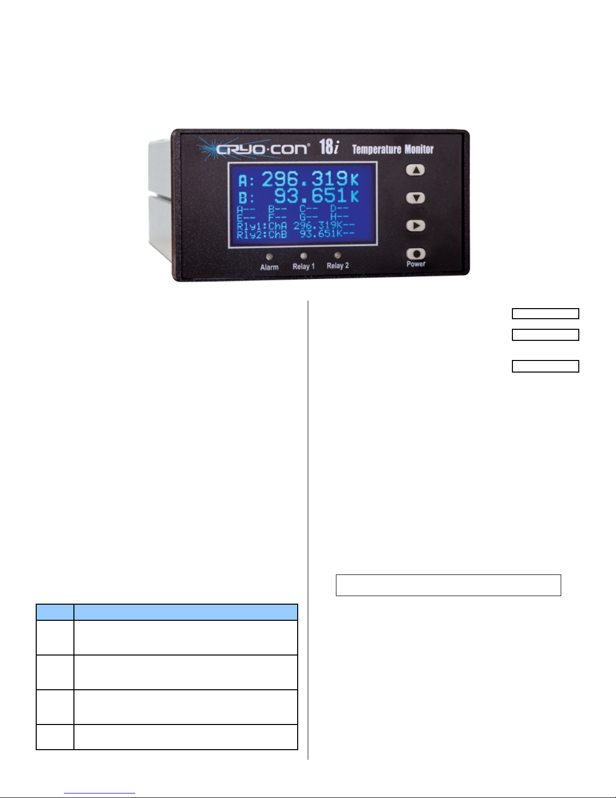
BASIC FRONT PANEL OPERATION
Pressing the Power() key for two seconds will toggle the monitor's
power on and off.
Several formats of the home screen are available to display different
information. Scroll through these formats by pressing the Right(►) key.
Setup and configuration functions are performed by working with the
monitor’s menu tree. To access this tree from the Home display, press
the Enter() key.
Navigation through all menus is performed by pressing the Inc(▲) or
Dec(▼) keys. A cursor will scroll up or down to show additional lines.
Moving up the tree is done by pressing the Right(►) key. The Home
display is at the top of the tree.
The left most character on each line of a menu is the cursor. These
indicate as follows:
Pressing the Enter() key will select the function described on the
menu line.
+ Pressing the Enter() key will cause the cursor to flash. Then,
pressing the Inc(▲) or DEC (▼) keys will sequence through the
allowed choices for the line. To make a selection, press the Enter()
key again. To abort the selection process, press the Right(►) key.
Indicates a numeric entry field. To change the value displayed,
press the Enter() key and the cursor will flash. Then, press he
Inc(▲) key to increment the number or the Dec(▼) key to decrement
the number. When the desired value is shown, press the Enter()
key.
Key Description
Enter
1) From Home screen, go to the top level setup menu.
2) Within a setup menu, enter data or select a field.
3) Press and hold this key for two seconds to toggle power.
▲
INC
1) Scroll display up. 2) When in a field selection mode, abort
entry and return to scroll mode. 3) In a numeric field,
increment.
▼
DEC
1) Scroll display down. 2) When in a field selection mode,
abort entry and return to scroll mode. 3) In a numeric field,
decrement.
►
Right
1) Move up the menu tree one level. 2) In selection mode,
scroll to next selection.
TEMPERATURE DISPLAYS
A sensor fault condition is identified by a display of
a clipping or clamping message. This usually
indicates that the sensor is open, disconnected or
shorted.
If a temperature reading is within the measurement
range of the instrument but is not within the
specified Sensor Calibration Curve, a display of
seven dot (.) characters is shown.
LED INDICATORS
There are three LED indicators below the display. They indicate the
following:
Alarm (Red) – An enabled alarm condition is asserted.
Relay 1 (Green) and Relay 2 (Green) - Relay asserted.
Latched alarms and relays are cleared by pressing the Enter() key.
ETHERNET COMMUNICATION
An Ethernet connection can be established by using a standard RJ-45
patch cable. The monitor acts as a server with a default IP and subnet
mask is 192.168.1.4 and 255.255.255.0. The user can change this from
the front panel via a menu or from a web browser. DHCP can also be
selected.
To view the embedded web page, open a web browser and type the
default IP of 192.168.1.4 in the address bar.
The default port for the TCP server is 5000. The UDP server is at TCP+1.
WEB SERVER FUNCTIONS
Note: The embedded web server's default user name is
admin and default password is cryocon.
This secure server provides most of the functions required to view and
configure the instrument including the downloading of user-defined
sensors, real-time strip-charts, data-logging and firmware updates.
!!CLAMP!!
Page 2
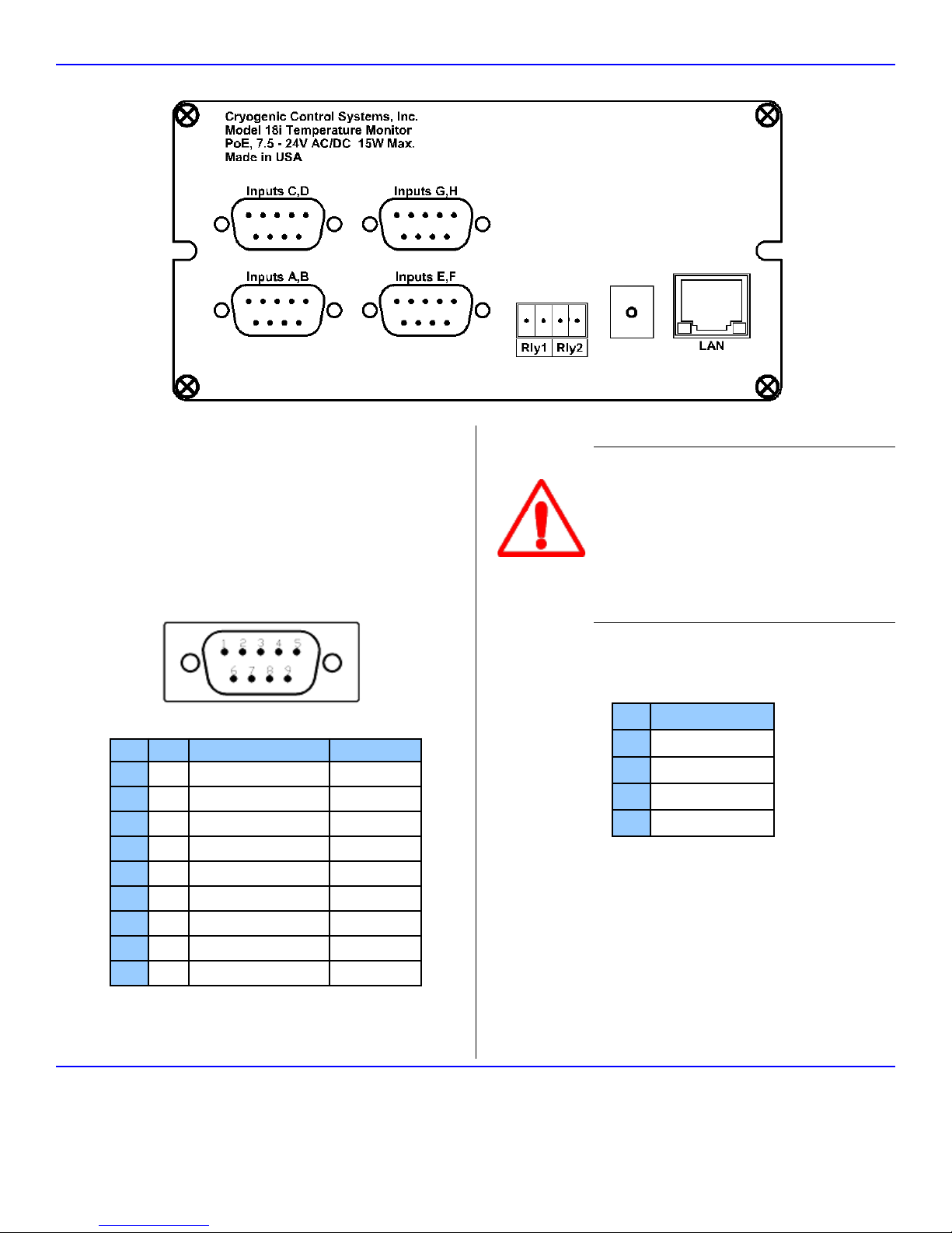
Rear Panel Connections
INPUT POWER CONNECTION
The external power supply provided with the monitor accepts 100 –
240VAC @ 50 – 60Hz and outputs 12VDC @ 1.0A. This may be plugged
directly into the monitor's power jack. Alternatively, any supply from 7.5 to
48V, AC or DC with a capacity of greater than 10VA may be used.
Power-Over-Ethernet is also supported. An IEEE-802.3AT Power-OverEthernet hub or injector is required. Plug the cable from this device into
the Ethernet input of the monitor.
SENSOR CONNECTIONS
Temperature sensors are connected by using the DB9 connectors
provided. There are two four-wire inputs on each connector.
Ch Pin Function Cable Color
A 8 Excitation Current(+) White
A 9 Excitation Current(-), Green
A 4 Voltage Sense(+) Red
A 5 Voltage Sense(-) Black
B 6 Excitation Current(+) White
B 7 Excitation Current(-) Green
B 1 Voltage Sense(+) Red
B 2 Voltage Sense(-) Black
B 3 Option power, 5VDC
Dual Sensor Cables (Cryo-con part number 4034-038) are provided for
each input channel. Cable color codes are shown in the table above.
Note that the shields of this cable are connected to the monitor's chassis
ground.
IMPORTANT: The monitor requires that an Earth
Ground reference connection is made at the rear
panel. Failure to provide this connection will result in
erratic measurements and can even damage input
circuits.
The sensor cables provided connect their shields to
the monitor's chassis; Therefore, the required Earth
Ground can be made by connecting the shield wire at
the opposite end to a ground reference point. This is
usually done by connecting it to the back-shell of the
cryostat connector.
RELAY CONNECTION
Relay connections are made on the rear panel using the 3.5mm, 4-pin
detachable terminal block provided.
Pin Function
1 Relay #1 N.O.
2 Relay #1 Common.
3 Relay #2 N.O.
4 Relay #2 Common.
Terminal block contacts are rated at 10.0A. Relay contact ratings are
10A@125 VAC, 5A@250VAC or 5A@30VDC
Cryogenic Control Systems, Inc.
PO Box 7012
Rancho Santa Fe, CA 92067
QS18I 10/18
E-mail: cctechsupport@cryocon.com
Telephone: 858-756-3900
www.cryocon.com
 Loading...