

Page 1
>
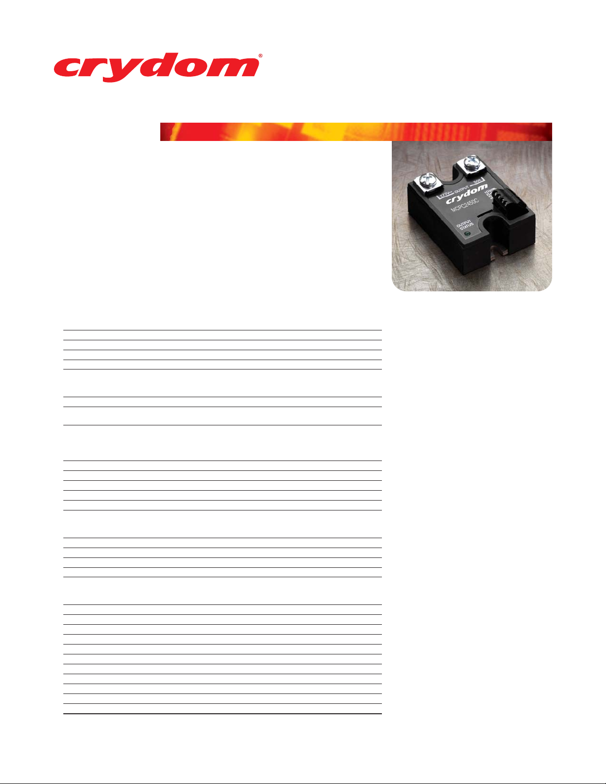
Burst Fire Controller / SSR in One Package
>
Low Voltage, Current, or Potentiometer Control
>
Output Status Indicator (Load Open, No Voltage)
>
0-100% Control Range
>
2 Time Base Periods Available
>
Separate Output Enable / Disable Control
>
SCR Based Output Load Switching
>
Internal Snubber Network Included
series MCBC
25-90Amp - 120/480 Vac - AC OUTPUT
GENERAL SPECIFICATIONS
Dielectric Strength 50/60Hz, Input/Output/Base 4000 Vrms
Insulation Resistance (Min.) @ 500 Vdc 10
Max. Capacitance Input/Output 10 pF
Ambient Operating Temperature Range -20 to 80°C
Ambient Storage Temperature Range -40 to 125°C
MECHANICAL SPECIFICATIONS
Weight: (typical) 3.0 oz. (86.5g)
Encapsulation Thermally Conductive Epoxy
Terminals - Power Screws and Saddle Clamps Furnished, Unmounted
OUTPUT SPECIFICATIONS 12 24 48
Operating Voltage (47-63 Hz) [Vrms] 48-140 180-280 300-530
Transient Overvoltage [Vpk] 400 600 1200
Max. Off-State Leakage Current @ Rated Voltage [mA] 5 7 12
Power Factor (Min.) with Max. Load 0.5 0.5 0.5
Maximum Voltage Drop (100% On) [Vpk] 1.6 1.6 1.6
Minimum Off-State dv/dt [V/µsec] 200 200 200
Max. Load Current [Arms] 25 50 90
Min. Load Current (mArms) 150 150 150
Max. Surge Current (16.6ms) [Apk] 250 625 1200
Thermal Resistance Junction to Case (R
Maximum I
INPUT SPECIFICATIONS* Minimum Typical Maximum
DC Voltage Supply Range [Vdc] [P1] 8 12 or 24 32
Input Current [mA] 28 30
Control Must Operate Voltage "On" [Vdc][P3] 5 32
Control Must Release Voltage "Off" [Vdc][P3] 0 4
Control Input Current [mA] [P3] 0 1.25
Control Nominal Input Impedance 30K
PLVI Range Option A [Vdc][P4]** 0.8 5
PLVI Range Option B [Vdc][P4]** 1 7
PLVI Range Option C [Vdc][P4]** 2 10
PLVI Range Option D [mA][P4] 4 20
Nominal Input Impedance Option A,B,C [Ohms][P4] 20K
Nominal Input Impedance Option D [Ohms][P4] 220
*Voltages are reference to GND (Ground = 0Vdc) P2.
**PLVI voltage can go up to max. supply voltage without damage.
Control Barrier Strip Screw Terminals
25 Amp 50 Amp 90 Amp
) [°C/W] 1.02 0.63 0.28
2
t for Fusing, (8.3 msec.) [A 2 s] 260 1620 6000
ØJC
9
Ohm
Voltage Suffix
Current Suffix
The Crydom MCBC series of Burst fire Controllers,
incorporate a complete burst Fire logic system and
Solid State Relay in one small industry standard
package. The MCBC uses micropocessor controlled
logic, accepts a wide range input logic power
supply, provides an output load status indicator,
and five modes of analog input control along with
an Enable / Disable control.
With 2 time base periods available, (10 and 20 AC
cycles), the MCBC provides a smooth proportional
control that minimizes electrical noise by utilizing
zero-cross detection and switching, firing only
complete AC cycles.
The MCBC does not require any calibration
adjustment, is optically isolated up to 4000 Vrms,
and is available in load rating up to 90 A and 530 Vac.
In addition, specialized AC Phase Detection Circuitry
allows the MCBC to be connected to only one side of
the load, minimizing installation wiring.
The MCBC series is particulary suited to electrical
heating applications where the electrical noise
generated by typical phase angle controllers can not
be tolerated.
© 2005 Crydom Corp, All Rights Reserved.
CrydomMCBC_J2705.pdf page 1 of 3
Specifications are subject to change without prior notice. Crydom and the Crydom logo are trademarks of Crydom Corp. Crydom
Page 2
series MCBC
1.87
(47.5)
.78
(19.8)
2.30
(58.4)
.45
(11.4)
1.10
(27.9)
8-32 TERMINAL
(2 PLACES )
1.80
(45.7)
MOUNTING
HOLE/SLOT
0.17 (4.3) DIA.
BASE PLATE
.125 (3.2)
Screw Torque Requirements:
8-32 Screws - 20in. lbs. (Screws dry without grease.)
Input Connections via Screw Type Barrier Strip
P4
P3
P2
P1
1.87
(47.5)
.78
(19.8)
2.30
(58.4)
.45
(11.4)
1.10
(27.9)
8-32 TERMINAL
(2 PLACES )
1.80
(45.7)
OUTPUT
STATUS
MOUNTING
HOLE/SLOT
0.17 (4.3) DIA.
BASE PLATE
.125 (3.2)
P3
P2
P1
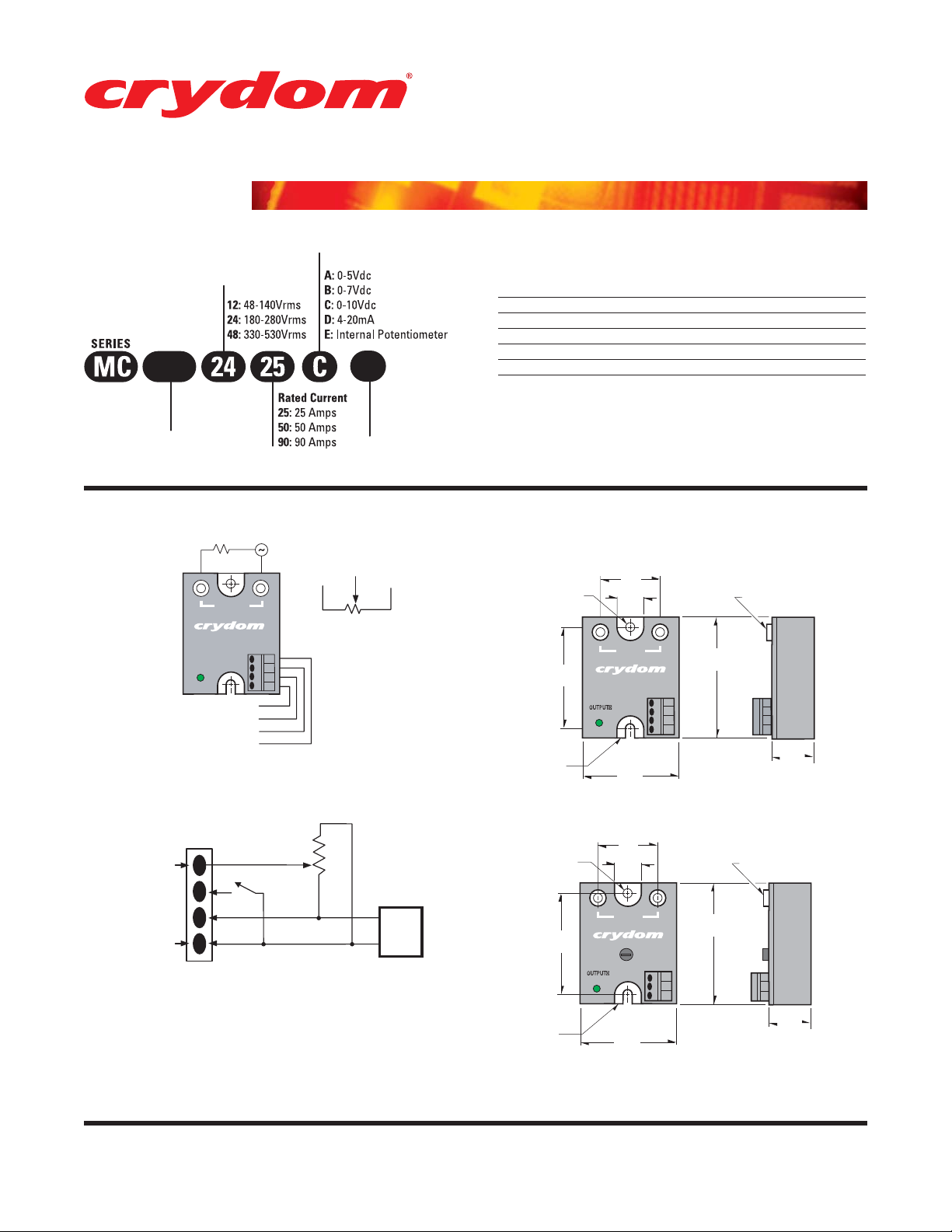
Analog Input OPTIONS: A,B,C,D
Analog Input Option: E (Internal Potentiometer)
1/L1
2/T1
OUTPUT
STATUS
1/L1
2/T1
25-90Amp - 120/480 Vac - AC OUTPUT
Part Number Nomenclature
Analog Control Signal
Line Voltage
BC
Product Type
Burst Fire
BC:
Controller
Electrical Connections
LOAD
OUTPUT
1/L1
OUTPUT
P4 0-5V, 0-7V, 0-10V, 4-20mA
STATUS
P1 8-32Vdc (+)
P2 Ground (-)
P3 ON/OFF Control
Wiring Example
(for Options A, B or C using an external potentiometer)
Terminal #4
Terminal #1
AC
2/T1
Setpoint Adjust
Enable
GND
+Vdc
P1
10K - 50K
For A,B or C Option
F
Time Base Period
10 AC Cycles
F:
20 AC Cycles
L:
P4
P2
10k to 50k pot for
Options A, B or C
DC
Supply
Output Status Functions
CONDITIONS LED
Initial Logic Supply On Flash Once
Load Voltage Missing / Load Open (w/control disabled) Flash Once Intermittently
Load Voltage Missing / Load Open (w/control enabled) Flash Twice Intermittently
Analog Input < Threshold Off
Analog Input > Threshold < max Varying Brightness
Analog Input > max On, Bright
Mechanical
Dimensions are in inches (millimeters)
© 2005 Crydom Corp, All Rights Reserved.
CrydomMCBC_J2705.pdf page 2 of 3
Specifications are subject to change without prior notice. Crydom and the Crydom logo are trademarks of Crydom Corp. Crydom
Page 3

Output vs. Analog Input Signal Curves
Duty Cycle vs Input Signal P4
10
20
8
14
6
12
4
8
AC Cycles On
2
4
(Complete Cycles Only)
0
0
0
1 2 3 4 5
0
1.4
0
4
2.8
2
4
7.2
10.4
Input Signal P4
Current Derating Curves
13.6
series MCBC
25-90Amp - 120/480 Vac - AC OUTPUT
4.2
5.6
6
8
16.8
Vdc
7
Vdc
10
Vdc
20
mA
ISO9001 Certified
Approvals
UL - Pending
© 2005 Crydom Corp, All Rights Reserved.
CrydomMCBC_J2705.pdf page 3 of 3
USA
Sales Support (877) 502-5500
Tech Support (877) 702-7700
Fax (619) 710-8540
Email: sales@crydom.com
Crydom Corp
2320 Paseo de las Americas, Suite 201
San Diego, CA 92154
EUROPE - UK
Telephone +44 (0) 1202 365070
Fax +44 (0) 1202 365090
Email: intsales@crydom.com
Crydom International Ltd.
7 Cobham Road
Ferndown Industrial Estate
Wimborne, Dorset BH21 7PE
Germany
Telephone +49 (0) 180 3000 506
Specifications are subject to change without prior notice. Crydom and the Crydom logo are trademarks of Crydom Corp.
ASIA - Thailand
Telephone +66 (0)2 665 2517
Fax +66 (0)2 665 2588
Crydom Asia
18/8 Fico Place 12th Floor
Soi Sukhumvit 21 (Asoke)
Klongtoey Nua, Wattana
Bangkok, Thailand 10110
 Loading...