

Page 1
S
eries
C
M
35-65
R
D/C
A
m
M
R
p
•
600 Vac - AC OUTPU
A
60
T
• Zero Voltage and Random
Turn-On Switching
• DIN Rail & Panel Mount
•
• Status Indicating LED
• DC or AC Control
• Integrated Overvoltage
Protection by Automatic
Self Turn-On (Suffix P)
MODEL NUMBERS CMRD6035 CMRD6045 CMRD6055 CMRD6065
OUTPUT SPECIFICATIONS
Nominal LIne Voltage (±10%) [Vrms] 600 600 600 600
Operating Voltage (47-63 Hz) [Vrms] 48-660 48-660 48-660 48-660
Max. Load Current @ 25˚C Ambient Temperature [Arms] 35 45 55 65
Min. Load Current, [Arms] 0.15 0.15 0.25 0.25
Transient Overvoltage [Vpk] 1200 1200 1200 1200
Max. Surge Current, (16.6ms) [Apk] 250 625 1000 1200
Max. On-State Voltage Drop @ Rated Current [Vpk] 1.7 1.7 1.7 1.7
Thermal Resistance Junction to Case (R
Maximum I2 t for Fusing, (8.3 msec.) [A2sec] 260 1620 4150 6000
Max. Off-State Leakage Current @ Rated Voltage [mArms] 1.0 1.0 1.0 1.0
Min. Off-State dv/dt @ Max. Rated Voltage [V/µsec] ➁ 500 500 500 500
Max. Turn-On Time 1/2 Cycle (DC Control), 10.0 msec (AC Control)
Max. Turn-Off Time 1/2 Cycle (DC Control), 40.0 msec(AC Control)
Power Factor (Min.) with Max. Load 0.5 0.5 0.5 0.5
INPUT SPECIFICATIONS
Control Voltage Range 4-32 Vdc 90-140 Vrms
Max. Reverse Voltage 32 Vdc —
Max. Turn-On Voltage 4.0 Vdc 90 Vrms
Min. Turn-Off Voltage 1.0 Vdc 10 Vrms
Max. Input Current 30.0mA —
Typical Input Current 14mA @ 5 Vdc 15mA @ 120 Vrms
GENERAL NOTES
➀ All parameters at 25˚ C unless otherwise specified.
➁ Off-State dv/dt test method per EIA/NARM standard RS-443, paragraph 13.11.1
➂ Turn-on time for DC control random turn-on versions is 0.02msec.
➃ Input circuitry incorporates active current limiter.
FastFax Document No. 171
SERIES CMRD/CMRA.
Rev. 111403
PAGE 5 OF 6
➂
➀
) [˚C/W] 1.02 0.63 0.31 0.28
θJC
➀
DC CONTROL AC CONTROL
➃
For recommended applications and more information contact:
USA: Sales Support (877) 502-5500 Tech Support (877) 702-7700 FAX (619) 710-8540
Crydom Corp, 2320 Paseo de las Americas, Ste. 201, San Diego, CA 92154
Email: sales@crydom.com
UK: +44 (0)1202 365070 FAX +44 (0)1202 365090 Crydom International Ltd., 7 Cobham
Road, Ferndown Industrial Estate, Ferndown, Dorset BH21 7PE, Email: intsales@crydom.com.
GERMANY: +49 (0)180 3000 506
CMRA6035 CMRA6045 CMRA6055 CMRA6065
GENERAL SPECIFICATIONS
Dielectric Strength 50/60Hz Input/Output/Base 4000 Vrms
Insulation Resistance (Min.) @ 500 Vdc 10
Max. Capacitance Input/Output 8 pF
Ambient Operating Temperature Range -40 to 80˚C
Ambient Storage Temperature Range -40 to 125˚C
Status Indicating Display Green LED
MECHANICAL SPECIFICATIONS
Weight: (typical) 16.8 oz. (476g)
Encapsulation: Thermally Conductive Epoxy
Terminals: Cage Type
Maximum Wire Size- Output: AWG 8 (3.8mm) Input: AWG12 (2.5mm)
Recommended Terminal Screw Torque Range:
Output: 10-15 in lb (1.1-1.7 Nm)
Input: 5-6 in lb (0.6-0.7 Nm)
© 2003 CRYDOM CORP, Specifications subject to change without notice.
WEB SITE: http://www.crydom.com
Featuring state-of-the-art Surface
Mount Technology, these SPST-NO
relays deliver proven reliability in the
most demanding applications. Output
consists of an SCR AC switch and is
available in zero-cross or random
turn-on versions.
Manufactured in Crydom’s ISO 9001
Certified facility for optimum product
performance and reliability.
9
Ohm
Page 2
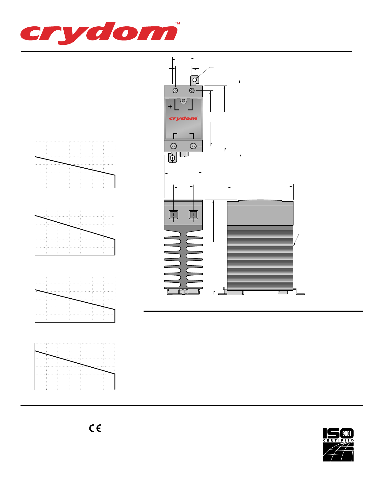
CURRENT DERATING CURVES
60
50
40
30
20
OUTPUT CURRENT (Arms)
10
20 30 4010
60
50
40
30
20
OUTPUT CURRENT (Arms)
10
20 30 4010
90
75
60
45
30
OUTPUT CURRENT (Arms)
15
20 30 4010
90
75
60
45
30
OUTPUT CURRENT (Arms)
15
20 30 4010
35 A
AMBIENT TEMPERATURE (ºC)
AMBIENT TEMPERATURE (ºC)
AMBIENT TEMPERATURE (ºC)
AMBIENT TEMPERATURE (ºC)
50 60 70 80
45 A
50 60 70 80
55 A
50 60 70 80
65 A
50 60 70 80
S
eries
C
M
R
35-65
1.0
(25.4)
0.75
(19.1)
I
N
S
P
U
U
T
T
A
S
T
INPUT
OUTPUT
1.75
(44.5)
.9
(22.9)
AVAILABLE OPTIONS
-10 Random Turn-On, Phase Controllable
Example: CMRD6035-10
E 24 Vac Input (18-36 Vac)
Example: CMRA6035E
Internal Overvoltage Protection.
P
Relay Will Self Trigger Between
900-1200Vpk. Not Suitable For Capacitive Loads.
Example: CMRD6035P
MOUNTING
HOLE/SLOT
0.17 (4.3) DIA.
2.5
(63.5)
4.3
(109.2)
3.0
(76.2)
3.5
(88.9)
MECHANICAL SPECIFICATIONS
All dimensions are in inches (millimeters)
3.0
(76.2)
D/C
A
m
p
•
600 Vac - AC OUTPU
M
HEAT SINK:
BLACK ANODIZED
ALUMINUM
R
A
60
T
APPROVALS
UL E116950
CSA LR81689
VDE 126921
FastFax Document No. 171
SERIES CMRD/CMRA.
Rev. 111403
PAGE 6 OF 6
© 2003 CRYDOM CORP, Specifications subject to change without notice.
For recommended applications and more information contact:
USA: Sales Support (877) 502-5500 Tech Support (877) 702-7700 FAX (619) 710-8540
Crydom Corp, 2320 Paseo de las Americas, Ste. 201, San Diego, CA 92154
Email: sales@crydom.com
UK: +44 (0)1202 365070 FAX +44 (0)1202 365090 Crydom International Ltd., 7 Cobham
Road, Ferndown Industrial Estate, Ferndown, Dorset BH21 7PE, Email: intsales@crydom.com.
GERMANY: +49 (0)180 3000 506
WEB SITE: http://www.crydom.com
 Loading...