

Page 1
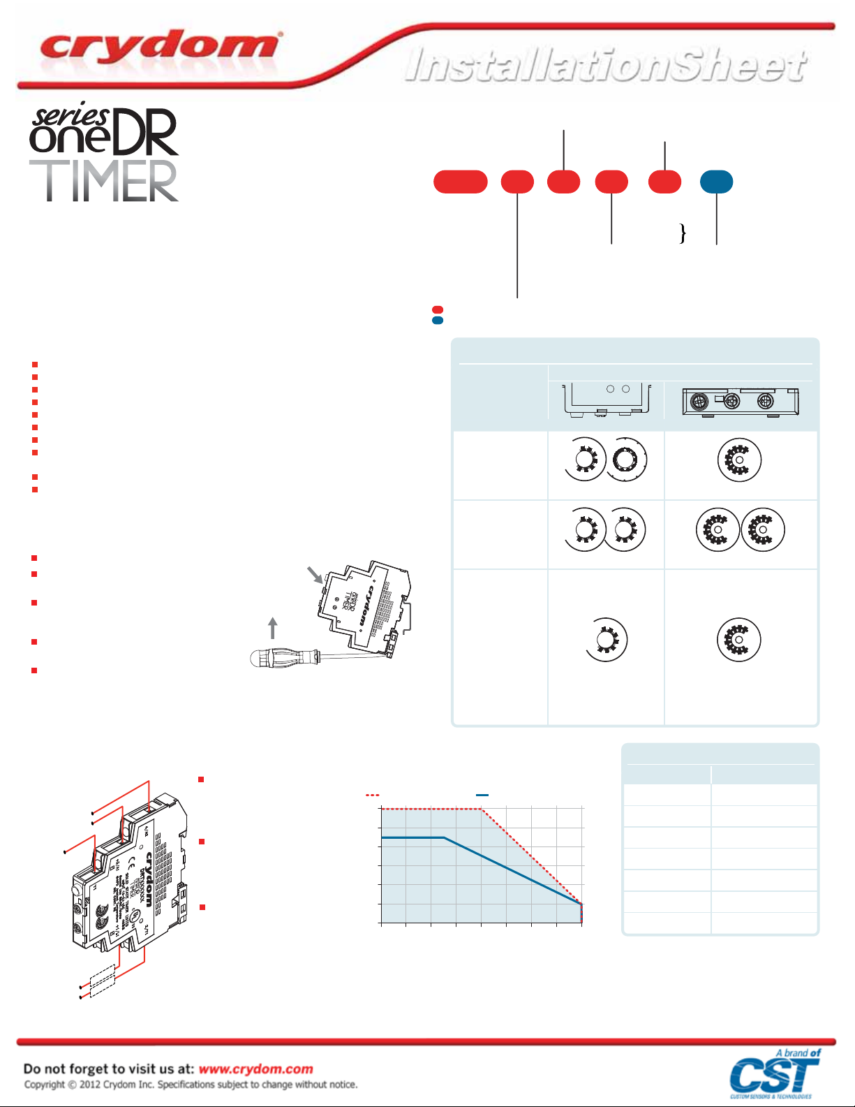
PART NUMBER NOMENCLATURE
Operating Voltage
Series
06: 60 VDC
24: 280 VAC
Rated Load Current
06: 6 Amps
DIN Rail Mounted AC & DC Output
Solid State Relay Timers
Crydom’s proprietary thermal management technology and proven Solid State Relay expertise are
now combined with advanced uP based timing in the SeriesOne DR Timer line offering models with
8 different precision timing functions with 18 variations in a compact 11 mm wide IP20 housing with
unique integrated heat sink designed for the direct control of a wide variety of resistive and
inductive loads.
FEATURES
Compact Size (11mm wide)
Single channel 6 Amps output power rating
Single channel 60 VDC & 280 VAC operating voltage ratings
12-24, 90-140 & 180-240 VAC/DC control input options available
8 Industry standard functions (A/At, B, C, D/Di, H/Ht, L/Li, Ac, Bw)
IP20 Housing with unique integrated heat sink
LED Input/Timer status Indicator
AC Output versions with Zero Voltage Turn-On for resistive loads and Random Turn-On for
inductive loads
UL Listed & cUL recognized
UL & IEC General Use & Motor Control rated
MOUNTING INSTRUCTIONS
Please read all installation instructions before using your SeriesOne DR Timer.
Install the relay on the DIN rail (as shown in fig.1).
Wire the relay to the input side. AWG #22 (0.3 mm
minimum, AWG #16 (1.3 mm
Wire the relay to the output side. AWG #22 (0.3
2
mm
) minimum, AWG #14 (2.1 mm2) x 2 or AWG #12
2
) x 1 (stranded/solid) maximum.
(3.3 mm
Maximum recommended terminal screw torque
input 4.4 in-lbs (0.5 Nm) & output 7 in-lbs (0.8 Nm).
If multiple units are installed be sure to follow
derating curves.
WARNING! Removing product from 35 mm rail incorrectly by not using the appropriate tool
could damage the latching system
(A)
2
) maximum .
(B)
2
)
To install on DIN rail
To remove from
DIN rail
DRTxxx06x
fig. 1
DRT
Timing Function
A: A/At, Delay on Make
B: Single Shot
C: Delay on Break
H: H/Ht, Interval
L: L/Li, Repeat Cycle
U: Multifunction
(A/At, H/Ht, D/Di,
B, C, Ac & Bw)
Required for valid part number
For options only and not required for valid part number
TABLE 1. Timer Settings
Timing
Function
U
Multifunction
[A/At, H/Ht, D/Di,
B, C, Ac, Bw]
L
Repeat Cycle
A
Delay on Make
H
Interval
B
Single Shot
C
Delay on Break
INPUT
STATUS
10s
1s
1m
10m
1h
10h
100h
Range Function Fine Adjustment
10s
1s
1m
10m
1h
10h
100h
T on T off
10s
1s
100h
0624 DA R
Control Voltage
D: 12-24 VAC/DC
A: 180-240 VAC/DC
B: 90-140 VAC/DC
Identification
A
H
B
C
Di
Bw
Ac
10s
1s
1m
10m
1h
10h
100h
1m
10m
1h
10h
Switching Type
(24 suffix only)
AC
Blank: Zero Voltage Turn-On
Output
R: Random Turn-On
Only
Front ViewSide View
9
10
8
7
6
5
4
3
2
9
10
8
7
6
5
4
1
3
2
Fine Adjustment
9
10
8
7
6
5
4
3
2
Fine AdjustmentRange
1
9
10
8
7
6
5
4
1
3
2
1
WIRING DIAGRAM
AC/DC CONTROL
VOLTAGE
(Relay Input)
AC/DC SUPPLY
(Relay Output)
A1
Y1
Load
Load
DERATING CURVES
Terminals
A2
5 Terminal screws Pozidriv #1,
3/16 in (4.8 mm).
Wire Size
(B)
Maximum wire strip length
0.20 in (5.1 mm), maximum
0.28 in (7.1 mm).
Important Considerations
Be sure to use input and
output voltages within
operating ranges.
T1
L1
Load is allowed in either
terminal L1 or terminal T1
Single or Multi Unit
6
5
4
3
2
Load Current (Amps)
1
0
0 302010 40 50 60 70 80
LED indicates only input
status. It does not represent
output status.
DRTxxxx06x
(C)
Multiple Units no Spacing
Ambient Temperature (ºC)
TABLE 2. Timing Ranges
Identification Timing Range
1s
10 s
1 min
10 min
1 h
10 h
100 h
(A) For UL listing the housing can not exceed
130°C or the load terminals exceed 105°C
(B) Use copper conductors rated 75°C only.
(C) Minimum spacing between units is 11 mm.
(D) Timing accuracy ± 10%
0.1 min to 1 min
1 min to 10 min
0.1 h to 1 h
10 h to 100 h
(D)
0.1 s to 1 s
1 s to 10 s
1 h to 10 h
Rev. 111312
Page 2

TABLE 3. LED Status by Function
Function Control Voltage Y1 Timing Output State LED Status Notes
At function is identical to the A function except when Y1 is connected to A3 timing is paused. When Y1 is removed timing
resumes until relay times out. To reset timer remove control power.
C
L
C
L
A1Y1
A1Y1
C
L
C
L
T
T
T
T T T T
T
T
off
on
T
T
T
off
off
on
A
Ht function is identical to the H function except when Y1 is connected to A3 timing is paused. When Y1 is removed timing
resumes until relay times out. To reset timer remove control power.
H
To select between on time (Di) first or off time (D) first Y1 is connected. Default is On time (Di) first, for Off time (D) first
connect Y1. Equal On/Off time.
D
To select between on time (Li) first or off time (L) first Y1 is connected A3. Default is On time (Li) first, for Off time (L) first
connect Y1 to A3. Time delay is independent of each other.
L
Y1 switch can be momentary or maintained to A3. To reset timer
after relay has timed out Y1 has to be opened.
Y1 switch to A3 must be momentary for timing to begin. If during
timing Y1 is closed again the time delay is reset and will begin
again once Y1 is removed. Once timed out timer is reset and
ready for the next cycle.
To start Delay on Make (A) timing connect Y1 to A3 and maintain
until LED is on Solid then to start Delay on Break (c) portion
remove Y1 until relay times out. Removing Y1 During (A) portion or
Connecting Y1 during (c) portion will reset time for that portion.
Y1 to A3 switch can be momentary or maintained. If maintained
until relay has timed out removing it will start timing again. If
momentary and timers has timed out reapplying Y1 will start
timing again.
A/At
Delay On Make
H/Ht
Interval
D/Di
Repeat Cycle
L/Li
Repeat Cycle
B
Single Shot
C
Delay On Break
Ac
Delay On Make /
Delay On Break
Bw
Off
On
On
Off
On
On
Off
On
Off
On
Off
On
On
On
Off
On
On
On
On
Off
On
On
On
On
On
Off
On
On
On
Open
Open
Closed
Closed
Open
Open
Closed
Open
Open
Open
Open
Closed
Closed
Open
Open
Open
Open
Closed
Closed
Off
On
Timed Out
Off
On
Timed Out
Off
On
Off
On
Off
Off
On
Timed Out
Off
Off
Off
On
Timed Out
Off
Off
On
Timed Out
On
Timed Out
Off
Off
On
Timed Out
Off
Off
On
Off
On
Off
Off
On/Off
Off
On/Off
Off
Off
On
Off
Off
Off
On
On
Off
Off
Off
Off
On
On
Off
Off
Off
On
Off
Long Flashes/Short Flashes
Long Flashes/Short Flashes
Off
Long Flashes
On
Off
Long Flashes
Short Flashes
Off
Off
Off
Short Flashes
Long Flashes
Short Flashes
Off
Short Flashes
On
Long Flashes
Short Flashes
Off
Short Flashes
Long Flashes
On
Long Flashes
Short Flashes
Off
Short Flashes
Long Flashes
Short Flashes
C
t1 t2 t3
Y1
At
Ht
Di
Li
Ac
Bw
L
C
Y1
L
B
C
C
T
L
C
T
L
C
Y1
L
C
Y1
L
C
Y1
L
C
Y1
L
T=t1+t2+t3
t1 t2 t3
T=t1+t2+t3
T T T T
T
on
offTonToff
T
T
T
T
T
T
Rev. 111312
 Loading...