

Page 1
PRODUCT SELECTION
4-32 VDC
AVAILABLE OPTIONS
Datasheet
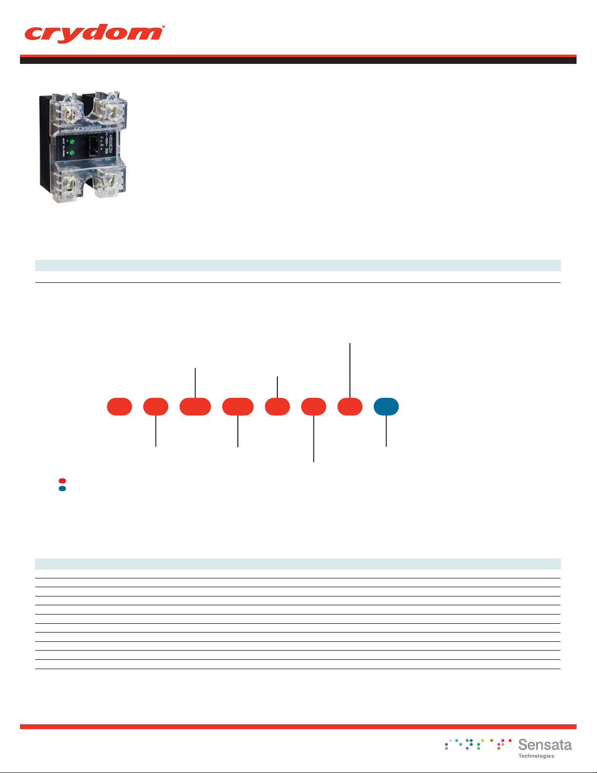
Evolution Dual Series
• 25A & 50A Output rating per channel @ 40°C
• 24 to 280 & 48 to 600VAC Operating voltage
• 4-32VDC Control input
• Three input termination options
• Zero turn-on outputs
• Input status LED indicator for each channel
• Available with IP20 “Touch-Safe” Covers
• UL508 Endurance Rating
CD2425W2U
CD2450W2U CD4825W2U CD4850W2U
Panel Mount
480V, 50A480V, 25A240V, 50A240V, 25AControl Voltage
Output Terminal
Orientation
U: A channel top,
B channel bottom
V: A channel on left,
B channel on right
Series
Operating Voltage
24: 24-280 VAC
48: 48-600 VAC
Control Voltage
W: 4-32 VDC
2524DC W 2 V H
Cover
C: Included
D: Not Included
Required for valid part number
For options only and not required for valid part number
*
Not all part number combinations are available.
Contact Crydom Technical support for information on
the availability of a specific part number.
OUTPUT SPECIFICATIONS
Operating Voltage (47-440Hz) [Vrms] 24-280 24-280 48-600 48-600
Load Current Range (3) [Arms] 0.15-25 0.15-50 0.15-25 0.15-50
Transient Overvoltage [Vpk] 600 600 1200 1200
Maximum Off-State Leakage Current @ Rated Voltage [mArms] 1.0 1.0 1.0 1.0
Minimum Off-State dv/dt @ Maximum Rated Voltage [V/µsec] (2) 500 500 500 500
Maximum 1 Cycle Surge Current (50/60) [Apk] 275/300 710/750 275/300 710/750
Maximum Surge Current 50Hz (20ms) [Apk] 275 710 275 710
Maximum On-State Voltage Drop @ Rated Current [Vpk] 1.3 1.3 1.3 1.3
Thermal Resistance Junction to Case (Rjc) [°C/W] 0.65 0.33 0.65 0.33
Maximum I² t for Fusing 50/60Hz (1/2 cycle) [A² sec] 380/370 2520/2320 380/370 2520/2320
Minimum Power Factor (with Maximum Load) 0.5 0.5 0.5 0.5
(1)
Rated Load Current
25: 25 Amps
50: 50 Amps
Input Connector
2: Key Locking Connector
3: 4 Pin Connector
accepting Screw Terminals
4: 4 Pin Spring Terminal
Thermal Pad
Blank: Not Included
H: Included
Cx4850xxxxCx4825xxxxCx2450xxxxCx2425xxxxDescription
Copyright © 2016 Crydom Inc. Specifications subject to change without notice.
Page 2

Panel Mount
Datasheet
INPUT SPECIFICATIONS
(1)
CxxxWxxxDescription
Control Voltage Range 4-32 VDC
Minimum Turn-On Voltage 4 VDC
Minimum Turn-Off Voltage 1 .0 VDC
Typical Input Current 10 mA @ 12 VDC
Nominal Input Impedance See Note (4)
Maximum Turn-On Time [msec] 1/2 Cycle
Maximum Turn-Off Time [msec] 1/2 Cycle
GENERAL SPECIFICATIONS
Dielectric Strength, Input/Output (50/60Hz) 4000 Vrms
Dielectric Strength, Input/Output/Base (50/60Hz) 4000 Vrms
Minimum Insulation Resistance (@ 500 V DC)
Maximum Capacitance, Input/Output 10 pF
Ambient Operating Temperature Range -40 to 80 °C
Ambient Storage Temperature Range -40 to 125 °C
Weight (typical) 3.0 oz (86.5 g)
Terminals Screw Type Output: 8-32
Max. Torque Output: 20 in lb (2.2Nm)
Max. Wire Size Output:2 x AWG 8 (3.8mm)
ParametersDescription
109 Ohm
GENERAL NOTES
1) All parameters at 25°C and per section unless otherwise specified.
2) Off-state dv/dt test method per EIA/NARM standard RS-443, paragraph 13.11.1
3) Heat sinking required, see derating curves.
4) Input circuit incorporates active current limitation
WIRING DIAGRAM
SSR Output Configuration
"U" Option Top-Bottom
Line/Load Connections
-
+DC
-
+DC
1
DC
LED
2
Current
Limiter
3
DC
LED
4
Current
Limiter
Trigger
Circuit
Trigger
Circuit
A1
AC
A2
AC
A
B
B1
AC
B2
AC
LOAD A
+A
-A
+B
-B
LOAD B
AC SUPPLY
AC SUPPLY
Copyright © 2016 Crydom Inc. Specifications subject to change without notice.
Contactor Output Configuration
"V" Option Left-Right
Line/Load Connections
A
B
L
O
A
D
A
AC SUPPLY
+A
-A
+B
-B
L
O
A
D
B
AC SUPPLY
Page 3

MECHANICAL SPECIFICATIONS
Tolerances: ± 0.02 in / 0.5 m
All dimensions are in: inches [millimeters]
Mounting
Hole/Slot
0.18 [4.5]
DIA.
2.300 [58.42]
1.875 [47.63]
Mounting
Hole/Slot
r 0.09 [2.2]
Panel Mount
Datasheet
.625 [15.89]
8X .191 [4.85]
IP20
1.700 [43.18]
2.635 [66.93]
2.300 [58.42]
IP00
1.700 [43.18]
MECHANICAL DIMENSIONS INPU T CONNEC TOR DI MENSIO NS SUGGESTED MATING
(shown without IP20 cover)
1.150 [29.21]
INPUT CONNECTOR
OPTION 2
1.100 [27.94]
1.100 [27.94]
0.120 [3.05]
2X .200 [5.08]
1.150 [29.21]
0.300 [7.62]
0.420 [10.67]
0.500 [12.71]
3X 0.100 [2.54]
4X 0.026 [0.66]
(SQUARE)
0.200 [5.08]
1.425 [36.20]
.803 [20.40]
CONNECTORS/PLUGS
Crimp Housing, Positive Latch
Molex 050579404
Accepts wires: AWG #24, 0.2 mm²
1.150 [29.21]
1.800 [45.72]
.803 [20.40]
1.800 [45.72]
0.413 [10.50]
0.122 [3.10]
0.606 [15.40]
N/A
1.046 [26.58]
1.201 [30.50]
INPUT CONNECTOR
OPTION 3
INPUT CONNECTOR
OPTION 4
1.059 [26.90]
3X 0.138 [3.50]
0.285 [7.25]
Copyright © 2016 Crydom Inc. Specifications subject to change without notice.
0.157 [4.00]
4X 0.031 [0.80]
(SQUARE)
Vertical Plug, Top Wire entry
Molex 039500-0004
Phoenix 1840382
Dinkle EC350V-04P
Vertical Plug, Rear Wire entry
Molex 39503-2004
Phoenix 1862878
Dinkle EC350RL-04P
Vertical Plug, Front Wire entry
Molex 39503-3004
Phoenix 1863178
Dinkle EC350R-04P
Vertical Spring Cage Plug, top Wire E
Phoenix 1939934
Dinkle 0221-2004
All 4 options accept wires: AWG #16 to 24
Accepts wires: AWG #16 to 24
Page 4

THERMAL DERATE INFORMATION
Panel Mount
Datasheet
CXXX25XXXX
(25 Amps per Channel)
50
40
30
20
10
Combined Load Current [Amps]
0
20 30 40 50 60 70 80
Ambient Temperature [°C]
1.0°C/W - HS103
1.5°C/W - HS-2
2.5°C/W -
AGENCY APPROVALS
Approvals
Designed in accordance with the requirements of IEC 62314
CXXX50XXXX
(50 Amps per Channel)
100
80
60
40
20
Combined Load Current [Amps]
0
20 30 40 50 60 70
Ambient Temperature [°C]
0.5°C/W - HS053
1.0°C/W - HS103
1.5°C/W - HS-2
80
E116950
Rev. 060916
Copyright © 2016 Crydom Inc. Specifications subject to change without notice.
Page 5

Panel Mount
Datasheet
DANGER / PELIGRO / DANGER /GEFAHR / PERICOLO / 危险
HAZARD OF
ELECTRIC
SHOCK,
EXPLOSION,
OR ARC FLASH.
• Disconnect all
power before
installing or
working with
this equipment.
• Verify all
connections
and replace all
covers before
turning on
power.
Failure to follow
these
instructions will
result in death
or serious injury.
RIESGO DE
DESCARGA
ELECTRICA O
EXPLOSION.
• Desconectar
todos los
suministros de
energia a este
equipo antes
de trabajar
con este equipo.
• Verificar todas
las
conexiones
y colocar todas
las
tapas antes
de energizer
el equipo.
El
incumplimiento
de estas
instrucciones
puede provocar
la muerte o
lesiones serias.
RISQUE DE
DESCHARGE
ELECTRIQUE
OU EXPLOSION
• Eteindre
toutes les
sources
d'énergie de
cet appareil
avant de
travailler
dessus de cet
appareil
• Vérifier tous
connections, et
remettre tous
couverts en
olace avant de
mettre sous
De non-suivi de
ces instructions
provoquera la
mort ou des
lésions sérieuses
sérieuses.
GEFAHR EINES
ELEKTRISCHE
N SCHLAGES
ODER EINER
EXPLOSION.
• Stellen Sie
jeglichen
St
rom ab, der
dieses Gerät
versorgt, bevor
Sie an dem
Gerät Arbeiten
durchführen
• Vor dem
Drehen auf
Energie alle
Anschlüsse
überprüfen
und alle
Abdeckungen
ersetzen.
Unterlassung
dieser
Anweisungen
können zum
Tode oder zu
schweren
Verletzungen
führen.
RISCHIO DI
SCOSSA
ELETTRICA O
DELL’ESPLOSI
ONE.
• Spenga tutta
l'alimentazion
e che fornisce
questa
apparecchiatu
ra prima del
lavorare a questa
apparecchiatu ra
• Verificare tutti
i colle
gament
e sostituire
tutte le coperture
prima della
rotazione
sull'alimentazi one
L'omissione di
seguire queste
istruz ioni
provocherà la
morte o di
lesioni serie
存在电击、
爆炸或电弧
闪烁危险
•
在操作此设
备之前请先
关闭电源。
若不遵守这些说明,
可能会导致严重的
人身伤害甚至死亡。
i
WARNING / AVERTISSEMENT / WARNUNG /ADVERTENCIA / AVVERTENZA / 警告
RISK OF MATERIAL DAMAGE AND HOT
ENCLOSURE
• The product's side panels may be hot, allow
the product to cool before touching.
• Follow proper mounting instructions including
torque values.
• Do not allow liquids or foreign objects to enter
this product.
Failure to follow these instructions can result in
serious injury, or equipment damage.
RIESGO DE DAÑOS MATERIALES Y DE
SOBRECALENTAMIENTO DE LA UNIDAD
• Los paneles laterales del producto pueden
estar calientes. Esperar que el producto se
enfríe antes de tocarlo.
• Respetar las instrucciones de montaje, y en
particular los pares de apretado.
• No dejar que penetren líquidos o cuerpos
extraños en el producto.
Si no se respetan estas precauciones pueden
producirse graves lesiones, daños materiales.
RISQUE DE DOMMAGE MATERIEL ET DE
SURCHAUFFE DU BOITIER
• Les panneaux latéraux du produit peuvent être
chauds. Laisser le produit refroidir avant de le
toucher.
• Respecter les consignes de montage, et
notamment les couples de serrage.
• Ne pas laisser pénétrer de liquide ni de corps
étrangers à l'intérieur du produit.
Le non-respect de cette directive peut entraîner,
des lésions corporelles graves ou des
dommages matériels.
RISCHIO DI DANNI MATERIALI E D'INVOLUCRO
CALDO
• I pannelli laterali dell'apparecchio possono
scottare; lasciar quindi raffreddare il prodotto
prima di toccarlo.
• Seguire le istruzioni di montaggio corrette.
• Non far entrare liquidi o oggetti estranei in questo
apparecchio.
La mancata osservanza di questa precauzione può
causare gravi rischi per l'incolumità personale o
danni alle apparecchiature.
GEFAHR VON MATERIALSCHÄDEN UND
GEHÄUSEERHITZUNG
• Die Seitenwände können heiß sein. Lassen Sie
das Produkt abkühlen, bevor Sie es berühren.
• Beachten Sie die Montageanweisungen,
• Führen Sie keine Flüssigkeiten oder
Fremdkörper in das Produkt ein.
Die Nichtbeachtung dieser Anweisung kann
Körperverletzung oder Materialschäden
zur Folge haben.
材料损坏和高温外壳的危险性
• 产品的一侧面板可能很热,在其冷却前请
不要触碰。
• 遵照正确的安装说明,包括扭矩值。
• 请勿让液体及其他异物进入本产品。
如不能正确执行这些操作说明,
极有可能造成严重人体伤害或者设备的损坏。
Copyright © 2016 Crydom Inc. Specifications subject to change without notice.
Page 6

Panel Mount
Datasheet
ANNEX - ENVIROMENTAL INFORMATION
The environmental information disclosed in this annex including the EIP Pollution logo are in compliance with People’s Republic of China
Electronic Industry Standard SJ/T11364 – 2006, Marking for Control of Pollution Caused by Electronic Information Products.
Part
Name
Semiconductor die
Solder
Toxic or hazardous Substance and Elements
Lead Mercury Cadmium Hexavalent Polybrominated Polybrominated
(Pb) (Hg) (Cd)
Chromium
(Cr (VI))
biphenyls
(PBB)
diphenyl ethers
(PBDE)
50
Copyright © 2016 Crydom Inc. Specifications subject to change without notice.
 Loading...