

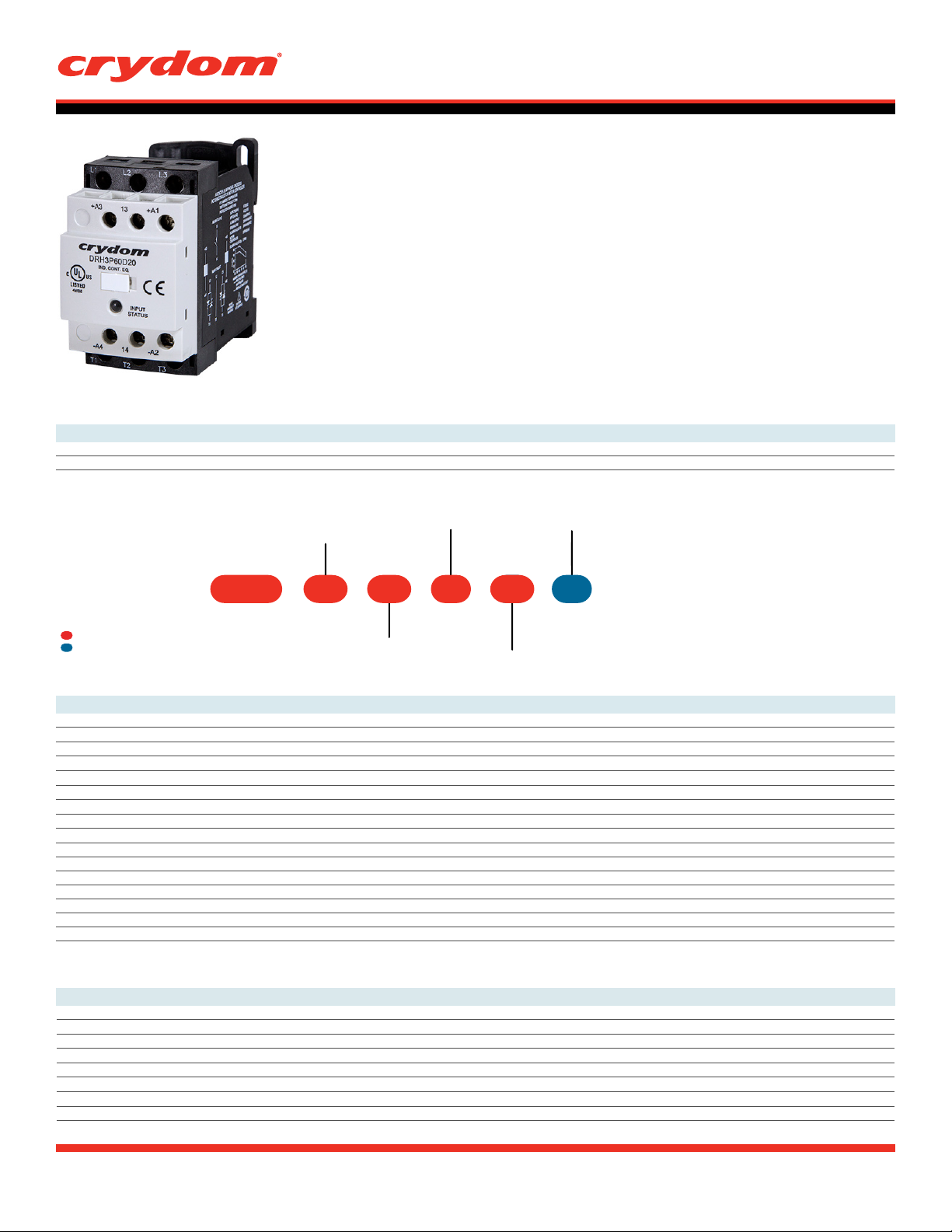
DRH Series
• Ratings up to 18 & 20 Amps at 600VAC
• Fits standard 35mm DIN Rail
• Integrated over-temperature protection
• Alarm output in case of over-temperature
• Multicolor LED with input status and alarm indicator
• AC or DC control
• Zero Voltage (resistive loads) or instantaneous (inductive loads) turn-on output
• C-UL-US Listed,
• Built-in Overvoltage Protection
• Fan controlled through thermistor and microprocessor to optimize fan operation
PRODUCT SELECTION
Control Voltage 18A
90-280 VAC/VDC DRH3P60A18
4-32 VDC DRH3P60D18
AVAILABLE OPTIONS
IEC Rated, CE & RoHS Compliant, Horsepower Rated
DIN Rail Mount
DataSheet
20A
DRH3P60A20
DRH3P60D20
Control Voltage
Series
DRH 3P 60 R
Required for valid part number
For options only and not required for valid part number
OUTPUT SPECIFICATIONS
Function
3P: Contactor
Operating Voltage
60: 48-600 VAC
(1)
A: 90-280 VAC/VDC
D: 4-32 VDC
A
18
U
Rated Load Current
18: 18 Amps (3 Controlled legs)
20: 20 Amps (2 Controlled legs)
Description
48-600 48-600
1200 1200
3 3
500 500
18 20
7.6 7.6
0.15 0.15
750 750
716 716
2330 2330
2560 2560
1.35 per channel 1.35 per channel
0.5 0.5
2/1.5 2/1.5
3/2.2 3/2.2
5/3.7 5/3.7
DRH3P60Dx
4-32 VDC
4 VDC
1 VDC
2 mA
17 mA
2k
1/2 Cycle
1/2 Cycle
RMS
RMS
]
(2)
]
(1)
RMS
]
RMS
(3)
]
]
(3)
RMS
Operating Voltage (47-63Hz) [V
Transient Overvoltage [Vpk]
Maximum Off-State Leakage Current @ Rated Voltage [mA
Minimum Off-State dV/dt @ Maximum Rated Voltage [V/μsec]
Load Current, General Use UL508/IEC62314 @ 40°C [A
Load Current, Motor Starting UL508 FLA/IEC62314 @ 40°C [A
Minimum Load Current [A
Maximum Surge Current [Apk] 1Cycle 60Hz
Maximum Surge Current [Apk] 1Cycle 50Hz
Maximum I²t for Fusing (8.33 msec) [A²sec]
Maximum I²t for Fusing (10 msec) [A²sec]
Maximum On-State Voltage Drop @ Rated Current [Vpk]
Minimum Power Factor (with Maximum Load)
Motor Rating UL 508/ IEC60947-4-2 [HP/kW] :240 VAC
Motor Rating UL 508/ IEC60947-4-2 [HP/kW] :380 VAC
Motor Rating UL 508/ IEC60947-4-2 [HP/kW] :480 VAC
INPUT SPECIFICATIONS
Description DRH3P60Ax
Control Voltage Range 90-280 VAC/VDC
Minimum Turn-On Voltage 90 VAC/VDC
Must Turn-Off Voltage 10 VAC
Minimum Input Current (for on-state) 1 mA
Maximum Input Current 3 mA
Nominal Input Impedance [Ohms] 100k
Maximum Turn-On Time [msec] 30
Maximum Turn-Off Time [msec] 40
Switching Type
Blank: Zero Voltage Turn-On
R: Instantaneous Turn-On
(4)
20A18A
DIN Rail Mount
DataSheet
POWER SUPPLY SPECIFICATIONS
Description
Voltage Range
Minimum Turn-On Voltage
Must Turn-Off Voltage
Maximum Source Current [mA]
Maximun Start Up Time [msec]
Maximun Shut Off Time [msec] 40
ALARM OUTPUT
Description
Maximum Contact Switching Voltage [Volts]
Contact Rated Current [A]
Minimum Recommended Contact Load [mA]
Static Contact Resistance (max. and init.)[Ohms]
Turn-On / Off Condition
GENERAL SPECIFICATIONS
(1)
(1)
(1)
DRH3P60Dx
8-32 VDC
8 VDC
3 VDC
125
20
DRH3P60Ax
90-265 VAC/VDC
90 VAC/VDC
5 VAC/VDC
40
50
500
DRH3P60D18
200 VDC, 120 VAC
0.5
10
0.2
See Status Chart
Description Parameters
Dielectric Strength, Input/Output/Base (50/60Hz) (5) 3750 Vrms
Minimum Insulation Resistance (@ 500 VDC)
Maximum Capacitance, Input/Output 20 pF
Ambient Operating Temperature Range -10 to 70 °C
Ambient Storage Temperature Range -40 to 70 °C
Weight (typical) 2 Controlled Legs (7.4 oz [210 g]) / 3 Controlled Legs (8.5 oz [242 g])
Housing Material UL94 V-0
Housing Color Black and Light Gray
LED Status Indicator (color) See Status Chart
Short Circuit Current Rating (6) 100kA
Pollution Degree 2
Protection Degree
Humidity
Control and Auxiliary Contact Terminal Screw Torque Range (in-lb/Nm) 12 / 1.36
Load Terminal Screw Torque Range (in-lb/Nm) 15 / 1.7
Input Terminal Wire Capacity 18-12 AWG (IEC 1-4 mm
Output Terminal Wire Capacity 18-10 AWG (IEC 1-6 mm2) (stranded /solid)
9
10
Ohm
IP20
85% non-condensing
2
) (stranded /solid)
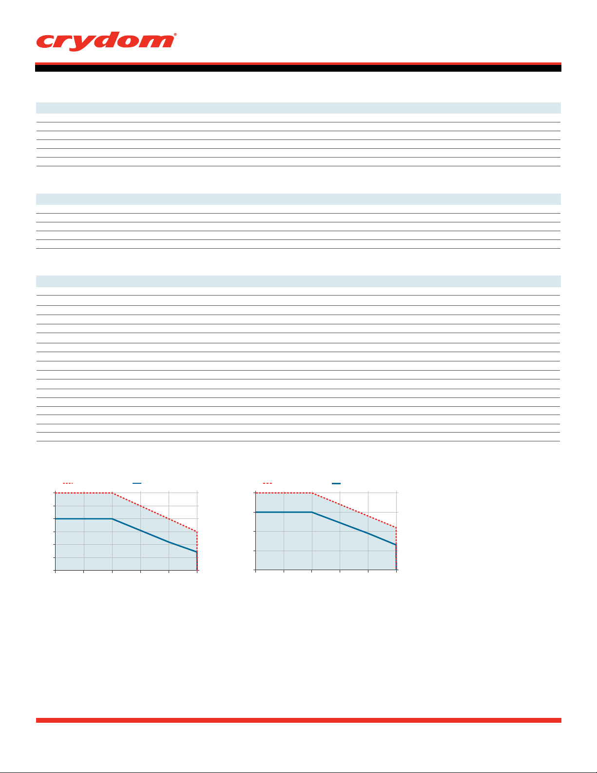
THERMAL DERATE INFORMATION
DRH3P60x18
(7)
Single unit
18
15
12
9
6
Load Current (Amps)
3
0
20 30 40 50 60 70
Ambient Temperature (ºC)
Multiple units
Single unit
20
15
10
5
Load Current (Amps)
0
20 30 40 50 60 70
DRH3P60x20
(7)
Ambient Temperature (ºC)
Multiple units

WIRING AND BLOCK DIAGRAM
L1
L2
L3
48-600 VAC, 50-60Hz
DIN Rail Mount
DataSheet
L1
L2
L3
/ > / > / >
L1 L2 L3
+A3 13 +A1
DRH3P60xxx
IND. CONT. EQ.
Power Supply
XXXX
INPUT
STATUS
CONTROL
INPUT
90-265 VAC/VDC (for A Control Voltage)
Motor Controller /
AC-53a Application
T1 T2 T3
M
3
(3 controlled legs model)
L1T1L2T2L3T3+A1
+A3
-A4
(2 controlled legs model)
L1T1L2T2L3T3+A1
+A3
8-32 VDC (for D Control Voltage)
Alarm Output (0.5 A/200 VDC, 120 VAC) Normally Open
DRHP60x18
Main Circuit
DRHP60x20
Main Circuit
-A4 14 -A2
T1 T2 T3
T1 T2 T3
-A2
General Use /
AC-51 Application
T1 T2 T3
Alarm Output
(DRHP60x18 & DRHP60x20)
13
14
-A4
-A2

DIN Rail Mount
DataSheet
SHORT CIRCUIT AND OVERLOAD PROTECTION FOR ALL DEVICES
IEC standard 60947-4-1 make a distinction between two different types of protection, (called “coordination”), which are designated types “1” and "2".
Any short-circuit that occurs is cleared safely by either type of coordination.
The only difference between the 2 categories concerns the extent of the SSR damage caused by the short-circuit.
Type "1" coordination requires that in the event of a sh
but permanent damage to the SSC is permissible. In this case the SSC may need to be replaced. For this type of co-ordination,
the use of fusing or circuit breakers adequate to protect the system and wiring from short circuits, (but not specifically considering SSC protection), can be used.
Type "2" coordination r
and in addition the SSR will be able to operate after the fault condition is repaired.
Type of coordination 1
For resistive loads:
equires that under a short-circuit condition, the circuit is interrupted, the SSC does not endanger persons or installations,
ort-circuit, the Solid State Contactor does not endanger personnel or installations,
Protection by Thermal Magnetic Circuit Breaker or by Fuse
Nominal
Current
0.15-20 A
For motor loads:
Class gG fuses
(example from Littlefuse)
CY14X51G25 DRH3P60x20 DRH3P60x18 (up to 18A)
Solid State Contactor
2 controlled legs
Solid State Contactor
3 controlled legs
Protection by Thermal Magnetic Circuit Breaker or by Fuse
Nominal Motor
Current
0.40-0.63 A CY14X51G16 DRH3P60x20 DRH3P60x18
0.63-1 A CY14X51G16 DRH3P60x20 DRH3P60x18
1-1.6 A CY14X51G25 DRH3P60x20 DRH3P60x18
1.6-2.5 A CY14X51G25 DRH3P60x20 DRH3P60x18
2.5-4 A CY14X51G25 DRH3P60x20 DRH3P60x18
4-6.3 A CY14X51G40 DRH3P60x20 DRH3P60x18
Thermal Magnetic Circuit Breaker
(Schneider Electric)
GV2ME04 / GV2P04
GV2ME05 / GV2P05
GV2ME06 / GV2P06
GV2ME07 / GV2P07
GV2ME08 / GV2P08
10 / GV2P10
GV2ME
GV2ME14 / GV2P14
Class gG fuses
(example from Littlefuse)
Solid State Contactor
2 controlled legs
Solid State Contactor
3 controlled legs
DRH3P60x18 (up to 7.6A)6.3-10 A CY14X51G40 DRH3P60x20 (up to 7.6A)
Type of coordination 2
For resistive loads:
Protection by Fuse
Nominal
Current
0.15-20 A LA50QS35-4 DRH3P60x20 DRH3P60x18 (up to 18A) 50 058 06.32 Z093908
For motor loads:
Semiconductor fuses with less than 2330 A2s
Littlefuse
Ferraz (Cylindric)SIBA1 (Cylindric)
Protection by Fuse
Nominal Motor
Current
0.15-7.6 A LA50QS40-4 DRH3P60x20 DRH3P60x1850 058 06.40 A093909
Semiconductor fuses with less than 2330 A2s
Littlefuse
Ferraz (Cylindric)SIBA1 (Cylindric)
Solid State Contactor
2 controlled legs
Solid State Contactor
2 controlled legs
Solid State Contactor
3 controlled legs
Solid State Contactor
3 controlled legs

STATUS CHART
1 2 3 4 5 6 7 8 9 10 11 12 13 14 15
Control Input A1
Power Supply A3
Output
Over Temperature
Alarm
Pre-alarm
Alarm Output
LED Color
Fan Speed
DIN Rail Mount
DataSheet
3s 3s2s 50% 50%75% 75%100% 100%0%3s
1, 15
Initial Condition
2, 14
Stand by condition. LED is blinking Blue. Fan is activated at full speed for 2 seconds after power is applied to A3
3
A1 is On, Output is activated, temperature rises. LED is Green
4, 12
Fan is activated at 50% speed. If A1 is disabled, LED changes to blinking Blue
5, 11
Fan is at 75% speed
6, 10
LED changes to blinking Red, fan is at full speed
7
Output is Off, Alarm Output is On, LED changes to solid Red
8
If A1 is disabled while alarm output is active, LED alternates between Blue and Red
9
LED is solid Red, temperature starts to fall
13
Fan is activated at 50% speed, temperature is steady
MECHANICAL SPECIFICATIONS
3.51
]
[89
2.91
[73.9]
0.23
[5.8]
3.41
[86.7]
DescriptionStep
1.23
[31.3]
2.29
[58.3]
LED Color
Blue
Tolerances: ±0.02 in / 0.5 mm
All dimensions are in: inches [millimeters]
+A1
13+A3
DRH3
2.58
[65.5]
IND. CONT. EQ.
XXXX
INPUT
STATUS
1.68
[42.7]
Green Red
1.78
[45.3]
3.76
[95.6]
-A2
14-A4
TERMINAL SCREW TYPE
Top/Bottom view (Fig. 1)
Fig. 1

ACCESSORIES
DIN Rail Mount
DataSheet
ID Marker
ID Marker
CNLB
CNLN
CNL2
Package of 10 plastic strip
comprising 10 individual markers
which can be placed for easy
identification during the use of
multiple units.
AGENCY APPROVALS
Certification in accordance with:
United States Standard for Industrial Control Equipment - UL 508 and
Canadian Standard Association for Industrial Control Equipment – C22.2 No. 14.
DRH series conforms to the harmonized EN standard EN/IEC 60947-4-2
Electromagnetic Compatibility:
IEC 61000-4-2 : Electrostatic Discharge – Level 3
IEC 61000-4-4 : Electrically Fast Transients – Level 3
IEC 61000-4-5 : Electrical Surges – Level 3
Vibration Resistance:
IEC 60068-2-6: Amplitude Range 10-55 Hz, Displacement 0.75mm
Shock Resistance:
IEC 60068-2-27: Peak Acceleration 15g, Duration 11msec.
E116949
DRH series has Environmental Product declarations type III conforming to ISO 14025.
GENERAL NOTES
(1)
All parameters at 25°C unless otherwise specified.
Relay will self trigger between 900-1200V, Not suitable for capacitive loads.
(2)
(3)
Mounted in the Vertical position.
(4)
Turn-on time for Instantaneous turn-on version is 4 msec.
(5)
For input to alarm output the dielectric strength is 1.5kV.
(6)
When protected with J Class fuses rated 600 VAC, 20 A or equivalent.
(7)
Minimum spacing to obtain max. current is 22mm between adjacent units.
Rev. 120715
 Loading...