

Page 1
DIN Rail Mount
Switching Type
Zero Voltage Turn-On
Control Voltage
For options only and not required for valid part number
Installation Sheet
DRH Series 3 Phase
Solid State Contactors
DIN Rail Mount
This installation sheet includes detailed mounting and wiring instructions which apply
for Crydom DRH 3 Phase Solid State Contactors. Be sure to visit the product series'
datasheet available at the Crydom website to complement this information. If you
have questions or need additional information please contact Crydom Tech Support.
Please read all mounting instructions before using your DRH Series Solid State
Contactor.
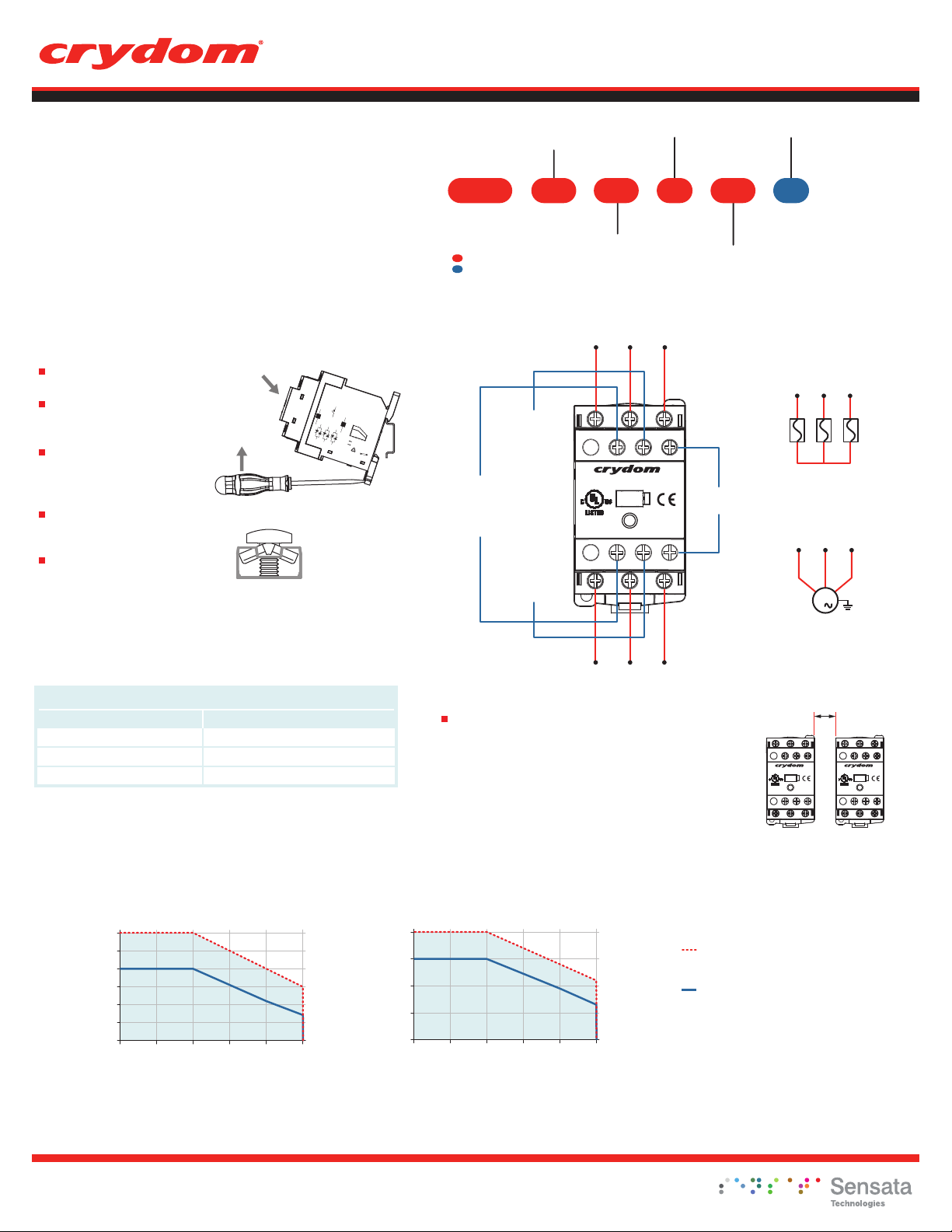
MOUNTING INSTRUCTIONS
Install the contactor on the DIN
rail (as shown in fig.1).
Wire the contactor to the input
side. AWG #18 (0.8 mm
AWG #12 (3.3 mm
Wire the contactor to the output
side. AWG #18 (0.8 mm
AWG #10 (5.3 mm
(stranded/solid) maximum.
Maximum recommended terminal
screw torque input 12 in-lb (1.36
Nm) & output 15 in-lb (1.7 Nm).
If multiple units are installed be
sure to follow derating curves
WARNING! Removing product from 35 mm rail incorrectly by not using the
appropriate tool could damage the latching system.
2
) minimum,
2
) x 2 maximum.
2
) minimum,
2
) x 2
(A, B)
To install on DIN rail
To remove from
DIN rail
AC SEMICONDUCTOR MOTOR CONTROLLER
ALARM OUTPUT
+A3
14
MAIN CIRCUIT
L1
L2
-A4
T1
T2
T3
fig. 1
fig. 2 Terminal
screw type.
Top/Bottom view.
AGENCIES IN APPROVAL PROCESS
40°C AMBIENT TEMPERATURE
TIGHTENING TORQUE: 1.7N.m
PROTECTION DEGREE: IP20
13
SUPPLY(A3/A4)
INPUT(A1/A2)
ALARM OUTPUT
GENERAL USE
+A1
IEC-60947-4-3 AC-51
MOTOR
CONTROLLER
IEC-60947-4-2 AC-53a
18
L3
12
AMPS
6
-A2
0
20 30 40 50
AMBIENT TEMPERATURE (°C)
MULTIPLE UNITS
(NO SPACING)
INSTALLED SINGLE UNIT
201525
ASSEMBLED
IN MEXICO
CAUTION
HOT SURFACE
8-32VDC
4-32 VDC
0.5A/200VDC
18A/48-600VAC
18A/48-600VAC
5HP/480VAC
3.7KW
60
70
50
PART NUMBER NOMENCLATURE
Series
Function
3P: Contactor
DRH 3P 60 R
Operating Voltage
60: 48-600 VAC
Required for valid part number
WIRING DIAGRAM
Power Supply
8-32 VDC (for D Control Voltage)
90-265 VAC/VDC (for A Control Voltage)
(C)
L1 L2 L3
L1 L2 L3
+A3 13 +A1
DRH3P60xxx
IND. CONT. EQ.
XXXX
-A4 14 -A2
T1 T2 T3
Alarm Output (0.5 A/200 VDC or Vpk) Normally Open
T1 T2 T3
INPUT
STATUS
A
A: 90-280 VAC/VDC
D: 4-32 VDC
18
Rated Load Current
18: 18 Amps (3 Controlled legs)
20: 20 Amps (2 Controlled legs)
CONTROL
INPUT
Blank:
R: Instantaneous Turn-On
General Use /
AC-51 Application
T1 T2 T3
Motor Controller /
AC-53a Application
T1 T2 T3
M
3
Overload current
protection needs to
be considered
TABLE 1. HP Ratings at Nominal Voltage
DRH @ 480 VACAmbient Temperature
40ºC
60ºC
80ºC
5 HP / 3.7 kW
3 HP / 2.2 kW
1.5 HP / 1.1 kW
DERATING CURVES
18
15
12
9
6
3
Load Current (Amps)
0
20 30 40 50 60 70
General Notes
(A) See compatible accessories in corresponding datasheet.
(B)
For optimal thermal performance, contactor vents should be aligned vertically to maximize airflow.
(C)
On models with 2 controlled legs, L2 and T2 are linked internally.
DRH3P60x18
Ambient Temperature (ºC)
Important Considerations
Be sure to use input and output voltages within operating ranges.
LED indicates input and alarm status. It does not represent output
status.
To achieve maximum ratings, there must be a minimum spacing of
0.9 in (22 mm) between the devices in free air. (See fig. 3)
20
15
10
5
Load Current (Amps)
0
20 30 40 50 60 70
DRH3P60x20
Ambient Temperature (ºC)
0.9 in
[22 mm]
Minimum
fig. 3 Multiple units mounting
for maximum ratings
Single unit , or multiple uni ts with spacing
greater than minimum (see fig. 3 )
Multiple units, no minimum spacing
bet ween components (see fig. 3)
Rev. 120915
Do not forget to visit us at: www.crydom.com
Copyright © 2015 Crydom Inc. Specifications subject to change without notice.
Page 2
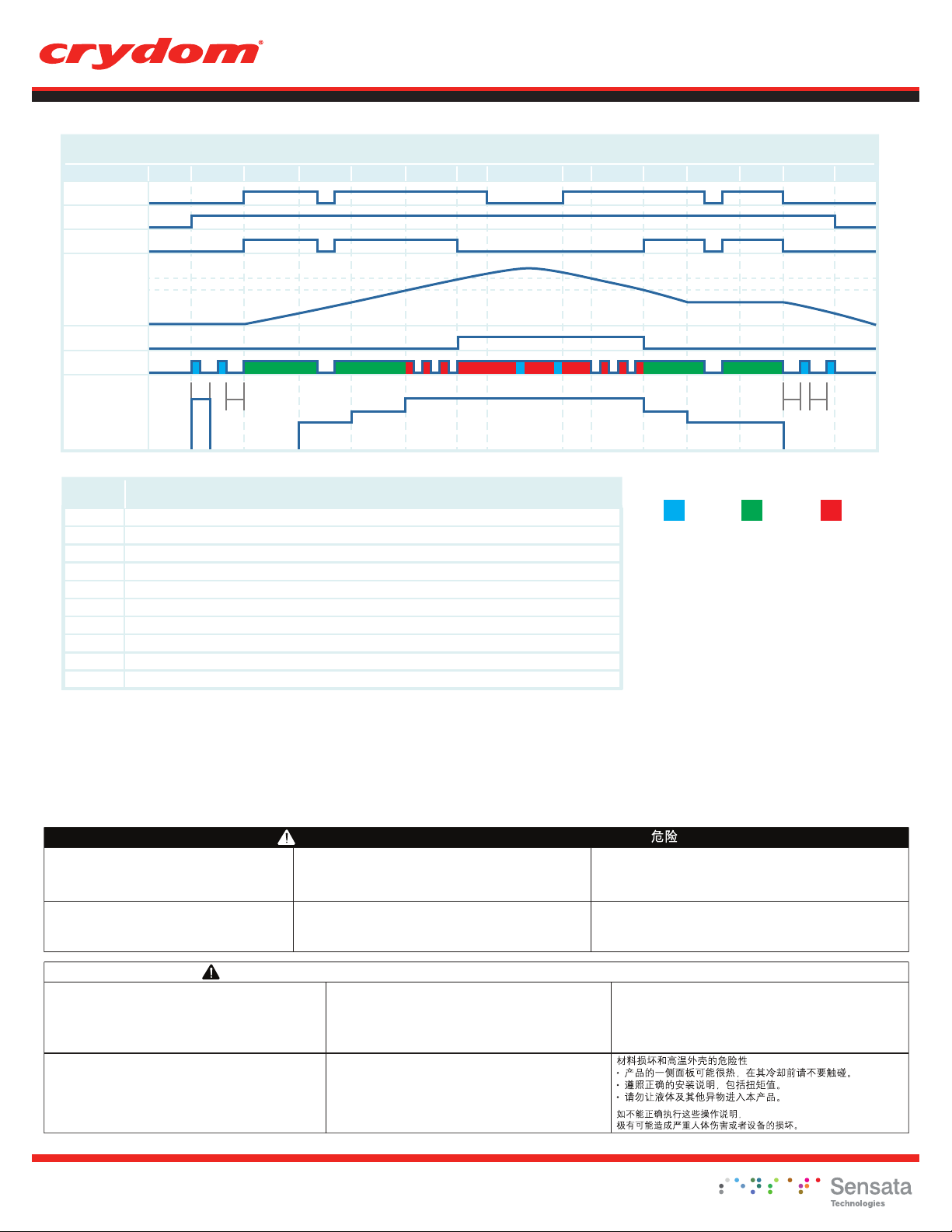
Control Input A1
Power Supply A3
Output
Over Temperature
Alarm
Pre-alarm
Alarm Output
LED Color
Fan Speed
DIN Rail Mount
Installation Sheet
TABLE 2. Status Chart
1 2 3 4 5 6 7 8 9 10 11 12 13 14 15
3s 3s2s 50% 50%75% 75%100% 100%0%3s
1, 15
Initial Condition
2, 14
Stand by condition. LED is blinking Blue. Fan is activated at full speed for 2 seconds after power is applied to A3
3
A1 is On, Output is activated, temperature rises. LED is Green
4, 12
Fan is activated at 50% speed. If A1 is disabled, LED changes to blinking Blue
5, 11
Fan is at 75% speed
6, 10
LED changes to blinking Red, fan is at full speed
7
Output is Off, Alarm Output is On, LED changes to solid Red
8
If A1 is disabled while alarm output is active, LED alternates between Blue and Red
9
LED is solid Red, temperature starts to fall
13
Fan is activated at 50% speed, temperature is steady
HAZARD OF ELECTRIC SHOCK, EXPLOSION OR ARC FLASH
•
Turn off power supply before working on this equipment.
Failure to follow these instructions will result in death or
serious injury.
RIESGO DE ELECTROCUCIÓN, EXPLOSIÓN O ARCO ELÉCTRICO
Desconecte toda alimentación antes de realizar el servicio.
Si no se siguen estas instrucciones provocará lesiones graves
o incluso la muerte.
DescriptionStep
DANGER / DANGER / GEFARH / PELIGRO / PERICOLO /
RISQUE D'ELECTROCUTION, D'EXPLOSION OU D'ARC ELECTRIQUE
•
Coupez l'alimentation avant de travailler sur cet appareil.
Le non-respect de ces instructions provoquera la mort ou des blessures
graves.
RISCHIO DI SCOSSA ELETTRICA, DI ESPLOSIONE O DI OFTALMIA DA FLASH
• Scollegare l'apparecchio dalla presa di corrente prima di qualsiasi intervento.
Il mancato rispetto di queste istruzioni provocherà morte o
gravi infortuni.
STROMSCHLAG-, EXPLOSIONS- ODER LICHTBOGENGEFAHR
• Vor dem Arbeiten an dem Gerät dessen Stromversorgung abschalten
Die Nichtbeachtung dieser Anweisungen führt zu Tod oder schwerer
Körperverletzung.
存在电击、爆炸或电弧闪烁危险
• 在操作此设备之前请先关闭电源。
若不遵守这些说明,可能会导致严重的人身伤害甚至死亡。
LED Color
Blue
Green Red
.
WARNING / AVERTISSEMENT / WARNUNG /ADVERTENCIA / AVVERTENZA / 警告
RISK OF MATERIAL DAMAGE AND HOT ENCLOSURE
• The product's side panels may be hot, allow the product to cool before
touching.
• Follow proper mounting instructions including torque values.
• Do not allow liquids or foreign objects to enter this product.
Failure to follow these instructions can result in
serious injury, or equipment damage.
RIESGO DE DAÑOS MATERIALES Y DE SOBRECALENTAMIENTO
DE LA UNIDAD
• Los paneles laterales del producto pueden estar calientes. Esperar que
el producto se enfríe antes de tocarlo.
• Respetar las instrucciones de montaje, y en particular los pares de apretado.
• No dejar que penetren líquidos o cuerpos extraños en el producto.
Si no se respetan estas precauciones pueden
producirse graves lesiones, daños materiales.
RISQUE DE DOMMAGE MATERIEL ET DE SURCHAUFFE DU BOITIER
• Les panneaux latéraux du produit peuvent être chauds. Laisser le produit
refroidir avant de le toucher.
• Respecter les consignes de montage, et notamment les couples de serrage.
• Ne pas laisser pénétrer de liquide ni de corps étrangers à l'intérieur du produit.
Le non-respect de cette directive peut entraîner, des lésions corporelles
graves ou des dommages matériels.
RISCHIO DI DANNI MATERIALI E D'INVOLUCRO CALDO
• I pannelli laterali dell'apparecchio possono scottare; lasciar quindi raffreddare
il prodotto prima di toccarlo.
• Seguire le istruzioni di montaggio corrette.
• Non far entrare liquidi o oggetti estranei in questo apparecchio.
La mancata osservanza di questa precauzione può causare gravi rischi
per l'incolumità personale o danni alle apparecchiature.
Do not forget to visit us at: www.crydom.com
Copyright © 2015 Crydom Inc. Specifications subject to change without notice.
GEFAHR VON MATERIALSCHÄDEN UND GEHÄUSEERHITZUNG
• Die Seitenwände können heiß sein. Lassen Sie das Produkt abkühlen,
bevor Sie es berühren.
• Beachten Sie die Montageanweisungen,
• Führen Sie keine Flüssigkeiten oder Fremdkörper in das Produkt ein.
Die Nichtbeachtung dieser Anweisung kann Körperverletzung oder
Materialschäden zur Folge haben.
Rev. 120915
 Loading...