

DR22 Series
For options only and not required for valid part number
Rated Load Current
(V and W suffixes only)
AC & DC Output DIN Rail Mount Solid State Relays
• Ratings up to 35 Amps at 600 VAC and 30 Amps at 200 VDC
• Built-in overvoltage transient protection on AC models
• Relay or Contactor configuration
• Integral heat sink eliminates the need for complex thermal calculations
• DBC substrate for superior thermal performance
• Optional "Elevator" screw suffix "W" allows the use of ring or lug type terminals
• 1kHz Maximum PWM frequency
• C-UL-US Listed and TUV approved
Output Specifications (A) DR2260x20x DR2260x30x DR2260x35x DR2220D20U DR2220D30U
Operating Voltage (47-440 Hz)
Absolute Maximum Rating [VDC] - - - 200 200
Transient Overvoltage [Vpk]
Maxumum Off-State Leakage Current @ Rated Voltage [mA] 1 1 1 0.1 0.2
Minimum Off-State dV/dt @ Maximum Rated Voltage [V/μsec] 500 500 500 - -
Load Current, General Use UL508/LC A IEC62314 @ 40°C [A
Load Current, Motor Starting UL508 FLA /LC B IEC62314 @ 40°C [A
Load Current, DC General Use UL508 @ 40°C [ADC] - - - 20 30
Load Current, DC Motor Starting UL508 FLA @ 40°C [ADC] - - - 4.1 5.4
Maximum Load Current
Minimum Load Current
Maximum 1 Cycle Surge Current (50/60 Hz) [Apk] 286/300 716/750 1290/1350 - -
Maximum On-State Voltage Drop @ Rated Current 1.35 Vpk 1.35 Vpk 1.30 Vpk 0.68 VDC 0.48 VDC
Maximum 1/2 Cycle I² t for Fusing (50/60 Hz) [A²sec] 409/375 2563/2343 8320/7593 - -
Minimum Power Factor (at Maximum load) 0.5 0.5 0.5 - -
Maximum Surge Current [ADC] (10 msec) - - - 58 86
Maximum On-State Resistance [R
Maximum Pulse Width Modulation Frequency [Hz]
Motor Rating UL 508/IEC62314 [HP (kW)]: 120 VAC 0.5 (0.37) 1 (0.74) 2 (1.5) - -
Motor Rating UL 508/IEC62314 [HP (kW)]: 240 VAC 1.5 (1.1) 3 (2.2) 5 (3.73) - -
Motor Rating UL 508/IEC62314 [HP (kW)]: 480 VAC 3 (2.24) 5 (3.7) 10 (7.4) - -
Motor Rating UL 508 [HP (kW)]: 120 VDC - - - 1/3 (0.25) 1/2 (0.37)
(B)
]
RMS
]
RMS
(C)
-ON] [Ohms]
DS
(D)
48-600 V
RMS
1200 1200 1200 - -
20 30 35 - -
8.5/4.8 14/7.6 26/14 - -
20 A
RMS
100 mA
RMS
- - - 0.034 0.016
- - - 1000 900
48-600 V
30 A
100 mA
RMS
RMS
RMS
48-600 V
35 A
150 mA
RMS
RMS
RMS
Input Specifications (A) DR2260Axxx DR2260Dxxx DR2220DxxU
Control Voltage Range
Maximum Reverse Voltage - -32 VDC -32 VDC
Minimum Turn-On Voltage 90 VAC/VDC 4 VDC 4 VDC
Must Turn-Off Voltage 5 VAC/VDC 1 VDC 1 VDC
Minimum Input Current (for on-state) [mA] 6 10 11
Maximum Input Current [mA] 10 15 15
Nominal Input Impedance [Ohms] Current Limited Current Limited Current Regulated
Maximum Turn-On time 20 msec
Maximum Turn-Off time 30 msec 1/2 Cycle 100 μsec
90-280 VAC/VDC
(E) 4-32 VDC (F)
1/2 Cycle
(G)
General Specifications DR2260xxxx DR2220DxxU
Dielectric Strength, Input to Output (50/60 Hz) [V
Dielectric Strength, Input/Output/Case (50/60 Hz) [V
Minimum Insulation Resistance (@ 500 VDC) [Ohms]
Maximum Capacitance, Input/Output [pF] 8
Ambient Operating Temperature Range [ºC]
Ambient Storage Temperature Range [ºC] -40 to 100
Short Circuit Current Rating [kA]
LED Input Status Indicator Green
Weight (Typical) [oz] (g) Suffix "U" 10.5 (298), "V"&"W" suffixes 10.6 (301) 10.5 (298)
Housing Material UL94 V-0
Baseplate Material Aluminum
Hardware Finish Nickel Plating
Humidity 85% non-condensing
(J)
]
RMS
]
RMS
(H)
4000 3750
4000 2500
100 -
9
10
-40 to 80
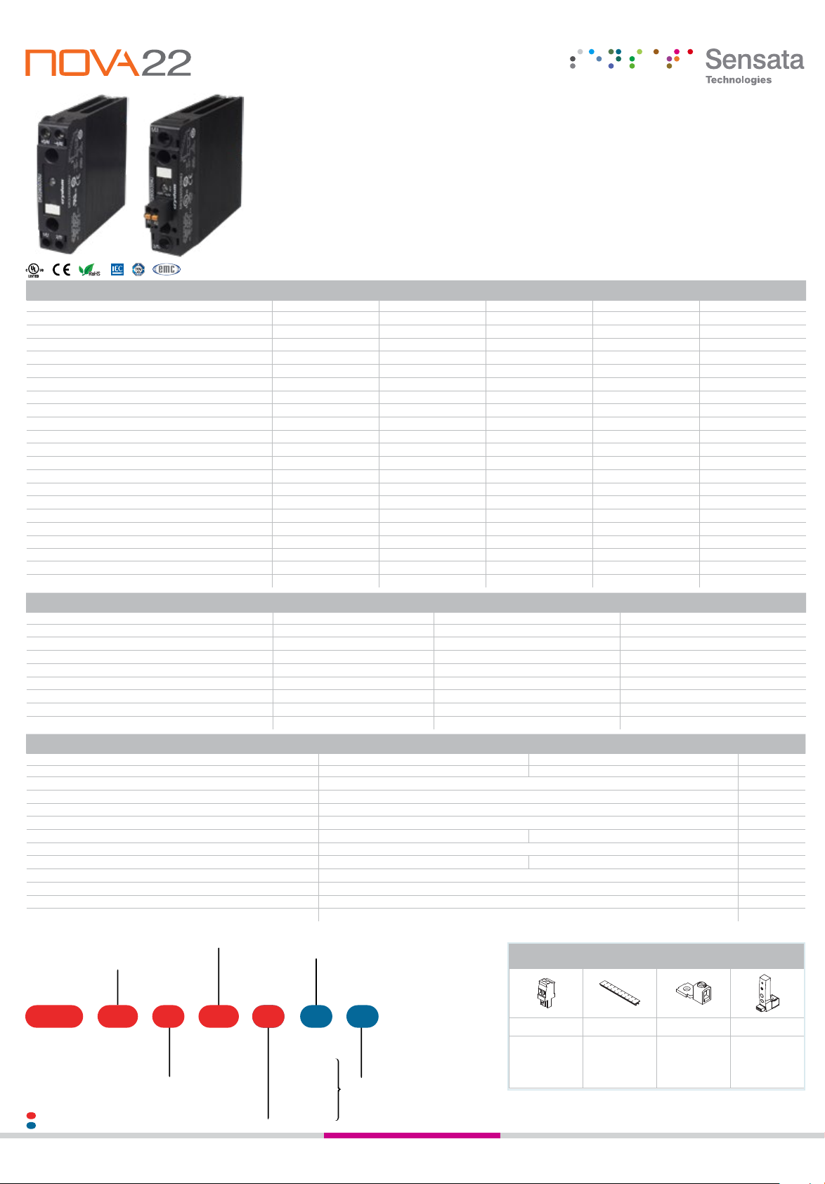
Part Number Nomenclature
20: 20 Amps
Operating Voltage
Series
20: 1-200 VDC
60: 48-600 VAC
DR22 60 A R
Control Voltage
A: 90-280 VAC/VDC
(AC Output only)
D: 4-32 VDC
Required for valid part number
30: 30 Amps
35: 35 Amps [High I
(AC Output only)
20 J
2
t]
U
V
Terminal Layout
U: Relay Configuration
V: Contactor
Configuration
(std. screw)
W: Contactor
Configuration
(elevator screw)
Switching Type
Blank: Zero Voltage Turn-On
R: Instantaneous Turn-On
(AC Output only)
Input Connector
Blank: Screw Terminal
J: Spring Terminal
AC
Output
only
Recommended Accessories for DR22 Series
Connectors ID Marker Lug Terminal Module
CP201
CP202
1-150 VDC 1-150 VDC
20 ADC 30 ADC
5 mA 5 mA
4-32 VDC
75 μsec
CNLB
CNLN
TRM0
TRM6
CNL2
DRML1
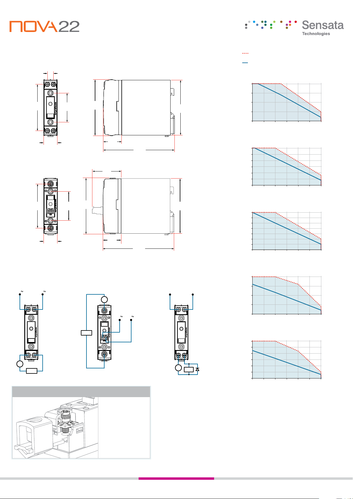
Tolerances: ±0.02 in / 0.5 mm
(+)
(
-
)
1.87
[116.5]
[116.5]
All dimensions are in: inches [millimeters]
Relay Configuration
0.39
[9.9]
INPUT
+3/A1 -4/A2
3.00
[76.2]
1/L1 2/T1
OUTPUT
1.88
[47.8]
3.67
[93.2]
3.54
[90]
Derating CurvesMechanical Dimensions
(H)
Single unit
Multiple units, no minimum spacing
between components
DR2260x20x
20
15
10
5
Load Current (Amps)
0
20 30 40 50 60 70 80
Ambient Temperature (ºC)
Contactor Configuration
2.85
[72.3]
Wiring Diagrams
Relay Configuration
AC Output
(+ / )
(- / )
-4/A2
+3/A1
INPUT
STATUS
2/T1
1/L1
VAC
Load
0.89
[22.5]
1/L1
3.62
1.88
[47.8]
[91.9]
2/T1
+3/A1 -4/A2
0.89
[22.5]
Contactor Configuration
Load
Elevator Screw (Suffix "W")
1.19
[30.2]
[47.5]
1.19
[30.2]
AC Output
V AC
1/L1
(- / )
(+ / )
INPUT
STATUS
+3/A1
-4/A2
2/T1
The Elevator Screw
option allows the screw
and clamp to be raised
out of the mating threads
completely. This provides
for the insertion and use
of a ring or lug type wire
terminal. See datasheet for
Compatible Terminals.
4.59
4.59
DR2260x30x
30
25
20
15
10
5
Load Current (Amps)
0
20 30 40 50 60 70 80
Ambient Temperature (ºC)
3.54
[90]
35
DR2260x35x
30
25
20
15
10
5
Load Current (Amps)
0
20 30 40 50 60 70 80
Ambient Temperature (ºC)
DR2220D20U
Relay Configuration
DC Output
(K)
-4/A2
+3/A1
INPUT
STATUS
20
15
10
5
Load Current (Amps)
0
20 30 40 50 60 70 80
Ambient Temperature (ºC)
DR2220D30U
30
-2
+1
+
+
V
-
Load
(L)
25
20
15
10
5
Load Current (Amps)
0
20 30 40 50 60 70 80
Ambient Temperature (ºC)
General Notes
(A) All parameters at 25ºC unless otherwise specified.
(B) Output will self trigger between 900-1200 Vpk. Not suitable for capacitive loads.
(C) Low current loads and high ambient temperature can affect turn-on time.
(D) 8 VDC Minimum control voltage. Resistive loads only. Consider switching losses; at maximum frequency reduce to
75% output current. Recommended suppressor diode connected at load side, see wiring diagram.
(E) Above 40ºC ambient temperature the maximum control voltage must not exceed 250 VAC/VDC.
(F) Increase minimum voltage by 1 V for operations from -20 to -40ºC.
(G) Turn-On Time for Instantaneous Turn-On versions is 0.1 msec.
(H) Operating range -20 to 60ºC for AC control models only.
(J) With appropriate class and rated fuse, see product datasheet for detailed info
(K) Load can be wired to either terminal 1 or terminal 2. Proper polarity must be observed for the DC control power supply,
with terminal 3 being positive with respect to terminal 4.
(L) DC inductive loads must be diode suppressed.
 Loading...