

Page 1
DP Series
DC Load Reversing Solid State Contactors
Crydom’s advanced DC Switching Technology is now conveniently packaged in a High Power
“H-Bridge” configuration with optional Soft Start/Ramp Up, Soft Stop/Ramp Down & Brake
features for use in DC Load Reversing applications including motors, brakes, clutches, electro
magnets, solenoids, plating baths and electrolytic cells. The DP Series Solid State DC Reversers
are an all-solid-state design with 2.5 Kv Optical Isolation and incorporate low dissipation power
FETs for fast and efficient Load control.
FEATURES
Convenient FET switches in H-bridge configuration
Built-in protective Forward/Reverse interlock function
UL & IEC ratings for general use & Motor loads
LED Status indicators for Operating Modes
MOUNTING INSTRUCTIONS
Please read all installation instructions before using your DP Series Solid State Contactor (SSC).
Choose one of the two mounting options and follow the instructions.
Mounting on Heat Sink
Select adequate heat sink (see thermal derating
(B)
curves).
Be sure to use thermal pad or grease between the
SSC and the selected heat sink.
DP Series Contactor mounting slots have a diameter
of 0.2 in (5.0 mm). Four screws are needed (not
included) to mount the SSC onto heat sink (See Fig.
1). Choose screw length considering the mounting
surface and that DP Series baseplate thickness is
0.125 in (3.2 mm).
Before applying full torque tighten down all 4 screws until they contact the baseplate.
Then, tighten them to 20 in-lbs (2.2 Nm) starting with one immediately followed by the one
in the diagonally opposite corner. After the first 2 screws are completely tightened,
proceed tightening the remaining 2 screws.
For optimal thermal performance heat sink fins should be oriented vertically to natural
airflow.
Mounting on Panel
Locate the panel section on which the DP Series SSC will be mounted. Panel mount
surface must provide adequate heat sinking capability. (B)
Be sure to use thermal pad or grease between the SSC and the panel.
DP Series Contactor mounting slots have a diameter of 0.2 in (5.0 mm). Four screws are
needed (not included) to mount the SSC onto panel. Choose screw length considering the
mounting surface and that DP Series baseplate thickness is 0.125 in (3.2 mm).
Before applying full torque tighten down all 4 screws until they contact the baseplate.
Then, tighten them to 20 in-lbs (2.2 Nm) starting with one immediately followed by the one
in the diagonally opposite corner. After the first 2 screws are completely tightened,
proceed tightening the remaining 2 screws.
WIRING DIAGRAM
(C)
1 / -
4 / L2 3 / L1
(A)
DC Power Supply
DC POWER SUPPLY SIDE
LOAD SIDE
Thermal pad
fig. 1 DP Series SSC
mounted on HS053 heat sink
2 / +
(D)
5
6
7
8
+VCC
GND
+FWD
+REV
(A)
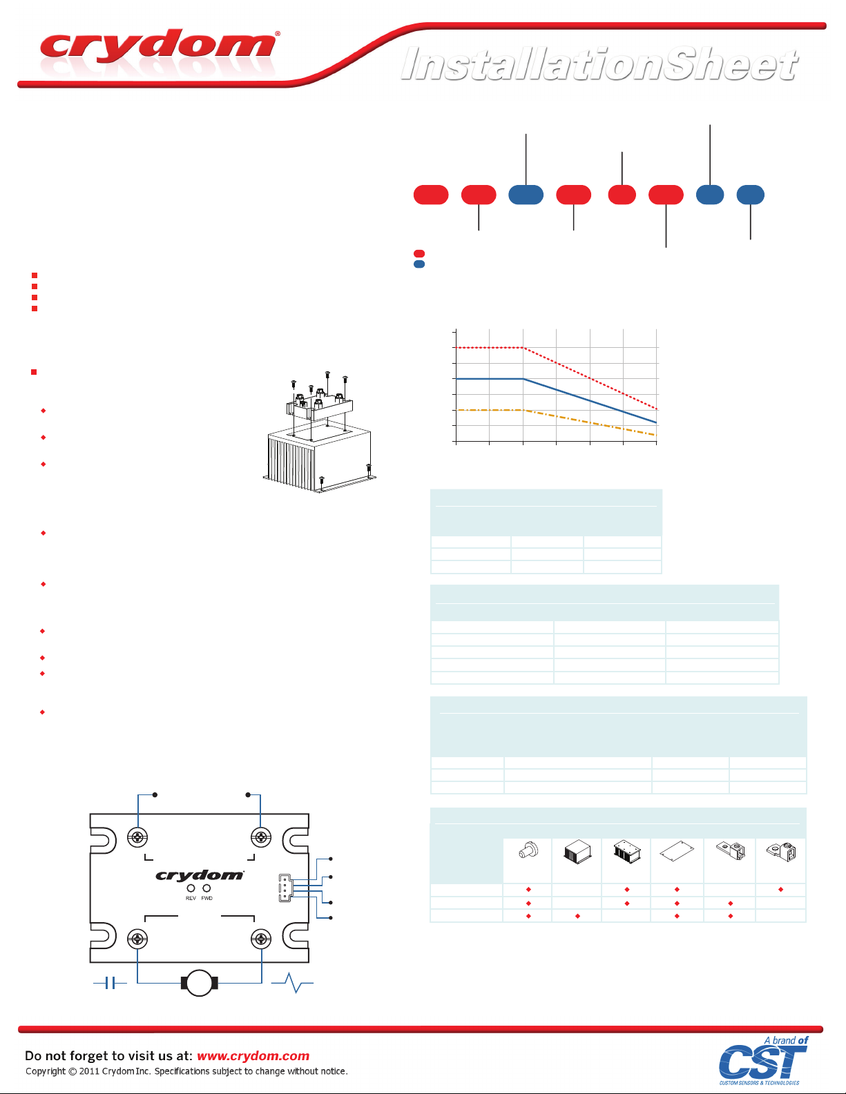
PART NUMBER NOMENCLATURE
Start Mode
Blank: Start
SA: Soft Start/Ramp Up, 0.2 sec
Series
SB: Soft Start/Ramp Up, 0.5 sec
SC: Soft Start/Ramp Up, 1 sec
DP 4R SB 60 40
Function
4R: 4 Channel DC Reversing
Required for valid part number
For options only and not required for valid part number
DERATING CURVES
70
DP4Rxx60x60xx
60
50
DP4Rxx60x40xx
40
30
DP4Rxx60x20xx
20
Load Current (Amps)
10
0
20 30 40 50 60 70 80
(B)
(E)
Control Voltage
D: 4.5-15 VDC
E: 18-32 VDC
D
Rated Operating Voltage
60: 48 VDC
Operational Current
20: 20 Amps
40: 40 Amps
60: 60 Amps
Ambient Temperature (ºC)
TABLE 1
DP Series
Part No.
DP4Rxx60x20xx HS103/HS103DR
DP4Rxx60x40xx
Required Heat Sink
[ºC/W]
1.5
1.0 HS103/HS103DR
0.5 HS053DP4Rxx60x60xx
Crydom Heat Sink
Part No.
TABLE 2
Status Functions Green LED (Forwa rd) Yellow LED (Reverse)
Initial Logic Supply Volt age On Flash Twice Flash Twice
Forward ON ON OFF
Reverse ON OFF ON
Dynamic Brake Flash Once Flash Once
Interlocking Flash 3x Intermittently Flash 3x Intermittently
TABLE 3
DP Series
Part No.
DP4Rxx60x20xx
DP4Rxx60x40xx
DP4Rxx60x60xx 25 (2.8)
Output Terminal
Screw / Clamp Combo Type 10-32 20 (2.2)
Hex Screw Type 1/4-20 with lock washers 25 (2.8)
Hex Screw Type 1/4-20 with lock washers
Maximum Torque
lbs in (N m)
TABLE 4
Accessories
DP Series
Part No.
DP4Rxx60x20xx
DP4Rxx60x40xx
DP4Rxx60x60xx
HS103
HS103DR
HSP-5
Stop Mode
Blank: Stop Mode matches Start Mode
B2: Dynamic Brake, 0.2 sec
B5: Dynamic Brake, 0.5 sec
B8: Dynamic Brake, 0.8 sec
B: Dynamic Brake, Continuous
H
B
Thermal Pad
Blank: Not Included
H: Included
Wire Size
for Max. Ratings
TRM1 TRM6HS053HK1 HSP-3
AWG (mm
12 (3.3)
8 (8.4)
6 (13.3)
2
)
DC
MotorCell Resistance
(A) See compatible accessories in TABLE 4.
(B) For maximum ratings use heat sink ratings in TABLE 1.
(C) Terminal (3/L1) is (+) during Forward operation. Terminal (4/L2) is (+) during Reverse operation.
(D) Suggested Input Mating Connector/Plug : Crimp Housing, Positive Latch (Molex 050579404).
(E) For a complete description of available Operating Modes, see definitions on reverse side of this sheet.
Rev. 060211
Page 2
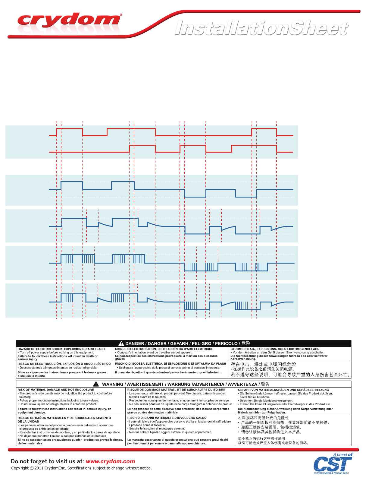
OPERATING MODES
Start: When either FWD or REV Control signal is applied, and after Control Signal Validation Delay, DC power
supply on terminals 1/- and 2/+ is directly connected to Load at terminals 3/L1 and 4/L2 with a polarity according
to the control signal. The start option can be combined with Stop and/or Dynamic Brake options.
Stop: Load is disconnected from DC power supply. All FET switches (S1, S2, S3 & S4) inside the DP Series SSC are
turned off. This simple Stop option is available only in combination with the simple Start option (suffix Blank).
Soft Start/Ramp Up: It is a modified Start where the DC power supply is connected to the load using a 200 Hz pulse
width modulation with a duty cycle going from 10% to 100%. Soft Start/Ramp Up time is defined by SA, SB and SC
suffixes. After Soft Start/Ramp Up time is elapsed, the Load will remain continuously energized for as long as FWD
or REV Control signal is applied. This option can be combined with Soft Stop/Ramp Down and Dynamic Braking
modes, but not with simple Stop.
Soft Stop/Ramp Down: It is a modified Stop where the DC power supply is disconnected from the Load using a 200
Hz pulse width modulation with a duty cycle going from 100% to 0%. After Soft Stop/Ramp Down time is elapsed,
Control Signals
+ V
FWD
Forward Control
Reverse Control
0
+ V
REV
0
the Load will remain continuously de-energized waiting for a new FWD or REV Control signal. Soft Stop/Ramp
Down time is tied to Soft Start/Ramp Up time selected by SA, SB and SC suffixes and can be combined with
Soft Start/Ramp Up only.
Dynamic Brake: It could be used as a modified Stop where the FET switches inside the DP Series SSC are
arranged in such a way that they provide a path for the Load Current to keep flowing after the DC power supply
has been disconnected. This mode allows for energy stored in some type of loads to be discharged. i.e. back
EMF on DC motors. Timing for Dynamic Brake is selected by suffixes B2, B5, B8 and B where the latest will
keep the braking or discharging path enabled for as long as FWD and REV Control signals are removed.
Interlock: It will shut down all FET switches inside the DP Series SSC within 0.2 sec after both control signals
FWD and REV are applied at the same time. An Interlock condition will trigger a modified Stop such as Soft
Stop/Ramp Down or Dynamic Brake whenever an option has been selected.
Load Voltage Signals
Start
Stop
DP4R60xxx
Start
Dynamic Brake
DP4R60xxxBx
(F)
+ V
DCS
- V
DCS
3 / L1 = + 4 / L2 = +
0
S1, S4 S3, S4
+ V
DCS
S1, S4
S1, S4 S2, S3 S2, S3
t
1
0
- V
DCS
t t t tInt Int
t
t
B
1
S1, S4 S1, S4 S2, S3 S3, S4
Soft Start/Ramp Up
Soft Stop/Ramp Down
DP4RSx60xxx
Soft Start/Ramp Up
Dynamic Brake
DP4RSx60xxxBx
+ V
DCS
0
- V
DCS
t
t
ST
S1, S4 S3, S4
+ V
DCS
t
SP
t t tInt Int
t
1
0
- V
DCS
t
t t t tInt Int
t
t
1
ST
B
(F) Load voltage signals shown are typical of a DC motor, behavior may change for other load types.
Int : Interlock
t : Control Signal Validation Delay
= 0.2 sec, except for
t Intt tt Int
t
1
Start / Stop (0.025 sec)
t
: 0.15 sec Break-before-make
1
delay
t
: Dynamic Brake time
B
B2: 0.2 sec
t
t
1
B
B5: 0.5 sec
B8: 0.8 sec
B: Continuous
t
: Soft Stop/Ramp Down time = t
SP
t
: Soft Start/Ramp Up time
ST
t
ST
t
ST
t
SP
t
1
t
t
1
B
SA: 0.2 sec
SB: 0.5 sec
SC: 1 sec
V
: VDC power supply
DCS
V
: Forward Control Signal
FWD
V
: Reverse Control Signal
REV
ST
Rev. 060211
 Loading...