

Page 1
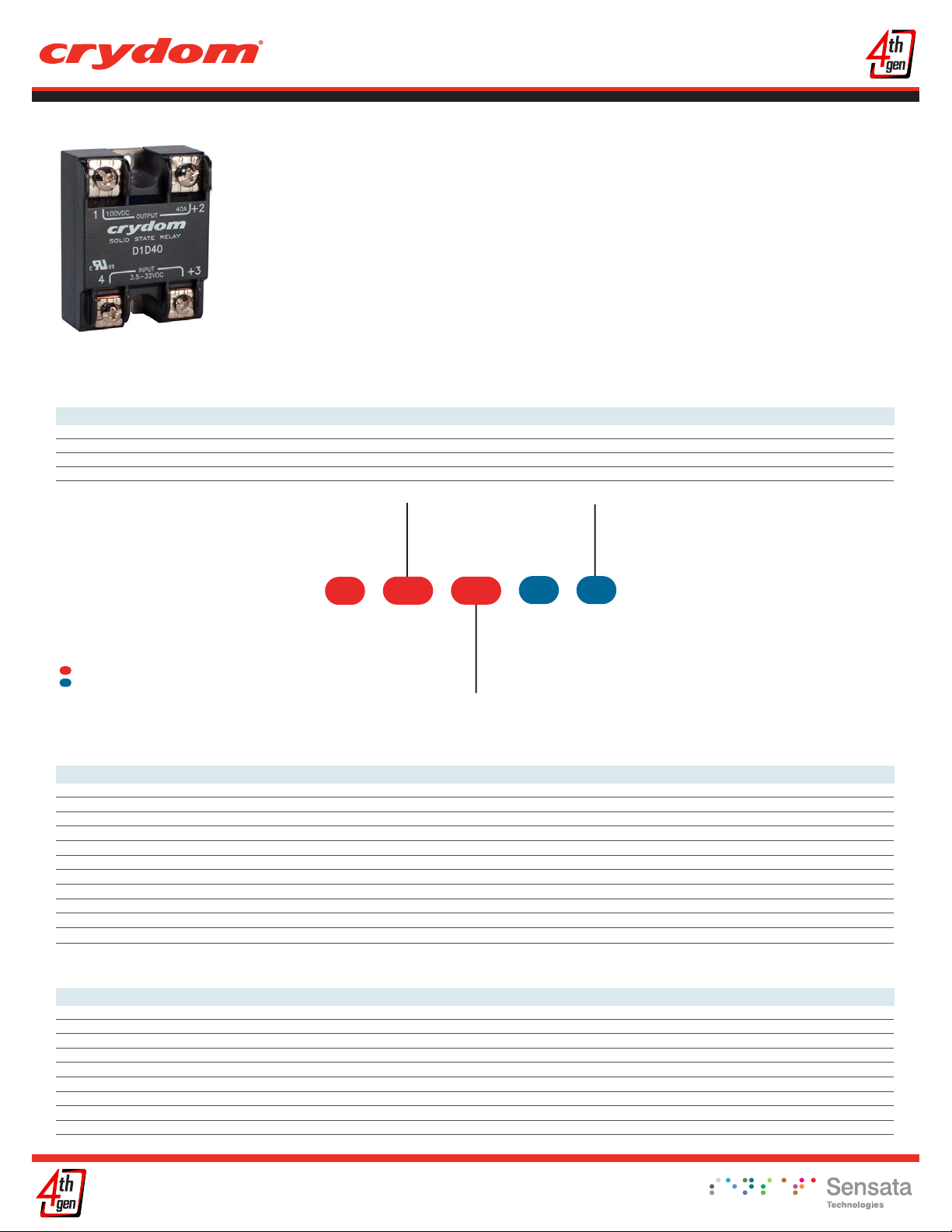
Panel Mount
Datasheet
1-DCL Series
• Ratings from 7 A to 40 A @ 200 VDC and
from 7 A to 10 A @ 500VDC
• Mosfet Output
• UL Approved, CE Compliant to EN60950-1
• Improved SEMS screw and washer
• Redesigned housing with anti-rotation barriers
PRODUCT SELECTION
Load Voltage 7 A 10 A 12 A 20 A 40 A
100 VDC D1D07L D1D12L D1D20L D1D40L
200 VDC D2D07L D2D12L D2D40L
400 VDC D4D07L D4D12L
500 VDC D5D07L D5D10L
• DC control
• EMC Compliant to Level 3
• Epoxy Free Design
AVAILABLE OPTIONS
Required for valid part number
For options only and not required for valid part number
Not all part number combinations are available.
*
Contact Crydom Technical Support for information on
the availability of a specific part number.
OUTPUT SPECIFICATIONS
Series
D
(2)
Operating Voltage
1D: 1-100 VDC
2D: 1-200 VDC
4D: 1-400 VDC
5D: 1-500 VDC
071D
L
Rated Load Current
07: 7 Amps
10: 10 Amps (500 VDC only)
12: 12 Amps (not for 500 VDC)
20: 20 Amps (100 VDC only)
40: 40 Amps (100 & 200 VDC only)
Description 7 A7 A12 A40 A12 A
Recommended Operating Voltage [Vdc] 1-72 1-72 1-150 1-300 1-385
Absolute Maximum Rating [Vdc] 100 100 200 400 500
Maximum Off-State Leakage Current @ Rated Voltage [mA] 0.2 0.3 0.3 0.3 0.2
Maximum Load Current [Adc]
Minimum Load Current [mA]
Maximum Surge Current (10msec) [Adc] 28 106 31 18 19
Maximum On-State Voltage Drop @ Rated Current [Vdc] 0.9 1 0.7 2.3 3.5
Maximum On-State Resistance [RDS-ON] [Ohms] 0.072 0.025 0.062 0.33 0.5
Thermal Resistance Junction to Case (Rjc) [°C/W] 2 0.68 0.71 0.56 0.6
Minimum Heat Sink for Rated Current @ 40°C [°C/W] 3 1 3 2 1
Maximum Pulse Width Modulation Frequency [Hz] (5) 4000 2500 2000 1200 1100
(3) 12 40 12 7 7
(4) 1 1 1 1 1
1-72 1-72 1-150 1-150 1-300
100 100 200 200 400
0.1 0.3 0.1 0.3 0.3
7 20 7 40 12
1 1 1 1 1
23 42 22 106 36
0.5 0.8 1.5 0.8 2.6
0.07 0.039 0.21 0.021 0.22
2 1.71 1.24 0.22 0.39
5 2 3 0.7 1
5000 3500 3500 950 900
Termination
Blank: Screws & clamps
K: Installed standoffs with
screws for PC Board
mounting (1)
K
12 A40 A7 A20 A7 A
10 A
1-385
500
0.3
10
1
29
3.3
0.33
0.43
0.7
900
INPUT SPECIFICATIONS
(2)
Description DC Control
Control Voltage Range 3.5-32 VDC
Maximum Reverse Voltage -32 VDC
Minimum Turn-On Voltage (6) 3.5 VDC
Must Turn-Off Voltage 1 VDC
Minimum Input Current (for on-state) 10 mA
Maximum Input Current 15 mA
Nominal Input Impedance Current Regulated
Maximum Turn-On Time [µsec] 100
Maximum Turn-Off Time [µsec] 100
Copyright © 2016 Crydom Inc. Specifications subject to change without notice.
Page 2
Panel Mount
Datasheet
GENERAL SPECIFICATIONS
(2)
ParametersDescription
Dielectric Strength, Input/Output/Base (50/60Hz) 3750 Vrms
Minimum Insulation Resistance (@ 500 VDC)
Maximum Capacitance, Input/Output 8 pF
Ambient Operating Temperature Range (7) -40 to 100 °C
Ambient Storage Temperature Range -40 to 125 °C
Weight (typical) 2.66 oz (75.5 g)
Housing Material UL94 V-0
Baseplate Material Aluminum
Input Terminal Screw Torque Range (in-lb/Nm) 13-15 /1.5-1.7
Load Terminal Screw Torque Range (in-lb/Nm) 18-20 / 2-2.2
SSR Mounting Screw Torque Range (in-lb/Nm) 18-20 / 2-2.2
Input/Load Terminal Screw Torque Range (in-lb/Nm) (1) w/”K” option 8-10 / 0.9-1.13
Input/Output Terminal Screw Thread Size #6-32 UNC / #8-32 UNC
Humidity per IEC60068-2-78 93% non-condensing
MTBF (Mean Time Between Failures) at 40°C ambient temperature (8)
MTBF (Mean Time Between Failures) at 60°C ambient temperature (8)
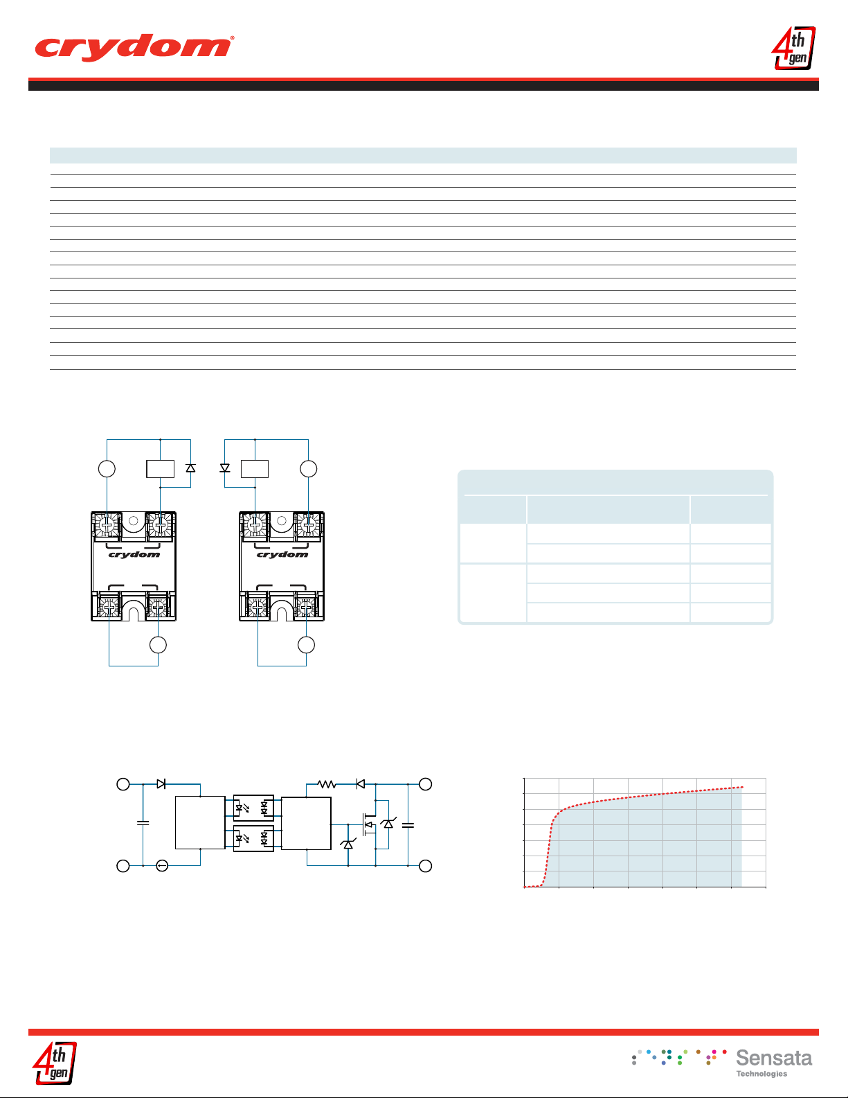
WIRING DIAGRAM
* Inductive loads must be diode suppresed.
+
V
-
Load
+
* *
Load
+
V
+
Terminals
OUTPUT
1
SOLI D ST AT E R ELA Y
4
INPUT
+2
+3
+
V
-
1
SOLI D ST AT E R ELA Y
4
OUTPUT
INPUT
+2
+3
+
V
-
Input
Output
109 Ohms
21,395,130 hours (2,441 years)
11,545,504 hours (1,317 years)
Recommended Wire Sizes
(Solid / Stranded)
24 AWG (0.2 mm
2 x 12 AWG (3.3 mm
20 AWG (0.5 mm
2 x 10 AWG (5.3 mm
2 x 8 AWG (8.4 mm
Wire Size
2
) / 0.2 [minimum]
2
) / 3.3 [maximum]
2
) / 0.518 [minimum]
2
) / 5.3
2
) / 8.4 [maximum]
Wire Pull-Out
Strength (lbs)[N]
10 [44.5]
90 [400]
30 [133]
110 [490]
90 [400]
EQUIVALENT CIRCUIT BLOCK DIAGRAMS
3
3
+
DC
Control
Circuit
4
-DC
4
Copyright © 2016 Crydom Inc. Specifications subject to change without notice.
Trigger
Circuit
Input Current vs Input Voltage
2
2
+DC
1
-DC
1
14
12
10
8
6
4
Input Current (mA)
2
0
0 5 10 15 20 25 30 35
Standard Regulated “DC” Inputs
DC Input Voltage
Page 3
Panel Mount
Datasheet
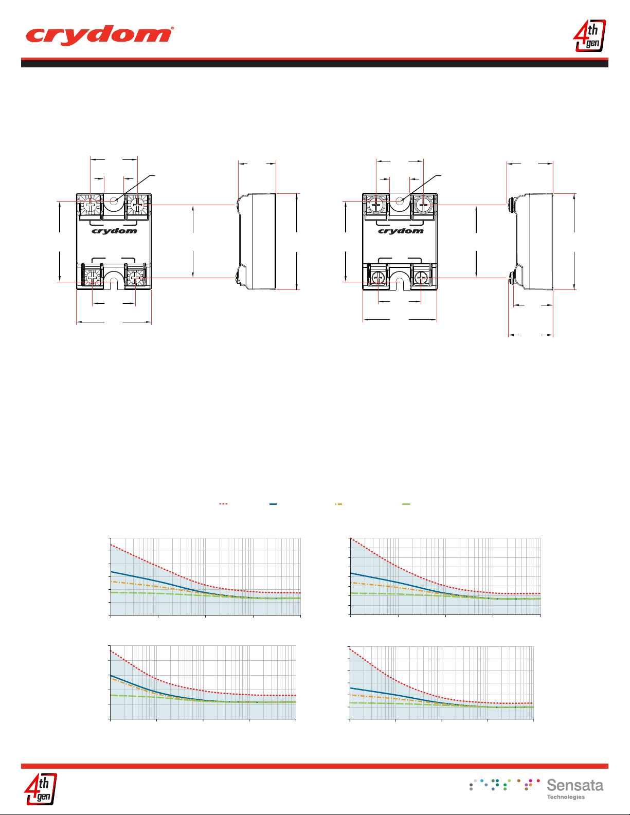
MECHANICAL SPECIFICATIONS
(2)
Tolerances: ±0.02 in / 0.5 mm
All dimensions are in: inches [millimeters]
1.88
[47.6]
1.1
[27.9]
0.49
[12.4]
OUTPUT
1
S OLID ST AT E RELA Y
4
INPUT
1.0
[25.4]
1.75
[44.5]
Screw Termination
Mounting
Hole/Slot
0.19 [4.9]
DIA.
+2
1.7
[43.2]
+3
0.89
[22.6]
2.25
[57.3]
1.88
[47.6]
Hex Standoff Termination (“K” Option)
1.1
[27.9]
0.49
[12.4]
OUTPUT
1
S OLID ST AT E RELA Y
4
INPUT
1.0
[25.4]
1.75
[44.5]
Mounting
Hole/Slot
0.19 [4.9]
DIA.
+2
1.7
[43.2]
+3
GENERAL NOTES
Option “K” is designed and tested for use with printed circuit boards or ring/fork terminals having a thickness between 0.031 and 0.093 inches (0.79 to 2.36 mm).
(1)
(2)
All parameters at Tc=25°C unless otherwise specified.
(3) Heat sinking required, see derating curves.
(4) Low current loads and high ambient temperature can affect turn-on time.
(5) 8VDC Minimum control voltage. Resistive loads only. Consider switching losses; at maximum frequency reduce to 75% output current.
(6) Increase minimum voltage by 1V for operations from -20 to -40°C.
(7) Decrease maximum control voltage 1.35V/°C above 80°C ambient temperature.
(8)
All parameters at 50% power rating and 100% duty cycle (contact Crydom tech support for detailed report).
(1)
1.04
[26.4]
(2 places)
0.93
[23.6]
(4 places)
1.0
[25.4]
(2 places)
2.25
[57.3]
For additional information or specific questions, contact Crydom Technical Support.
SURGE CURRENT INFORMATION
60
50
40
30
20
Surge Current (Amp)
10
0
0.1 1 10 100 1000
100
80
60
40
20
Surge Current (Amp)
0
0.1 1 10 100 1000
D1D07L
Surge Duration (msec)
D1D20L
Surge Duration (msec)
Single Pulse (i)
Duty Factor (10%) (ii)
Duty Factor (20%) (ii)
80
70
60
50
40
30
20
Surge Current (Amp)
10
0
0.1 1 10 100 1000
300
250
200
150
100
50
Surge Current (Amp)
0
0.1 1 10 100 1000
Duty Factor (50%) (ii)
D1D12L
Surge Duration (msec)
D1D40L
Surge Duration (msec)
Copyright © 2016 Crydom Inc. Specifications subject to change without notice.
Page 4
Panel Mount
Datasheet
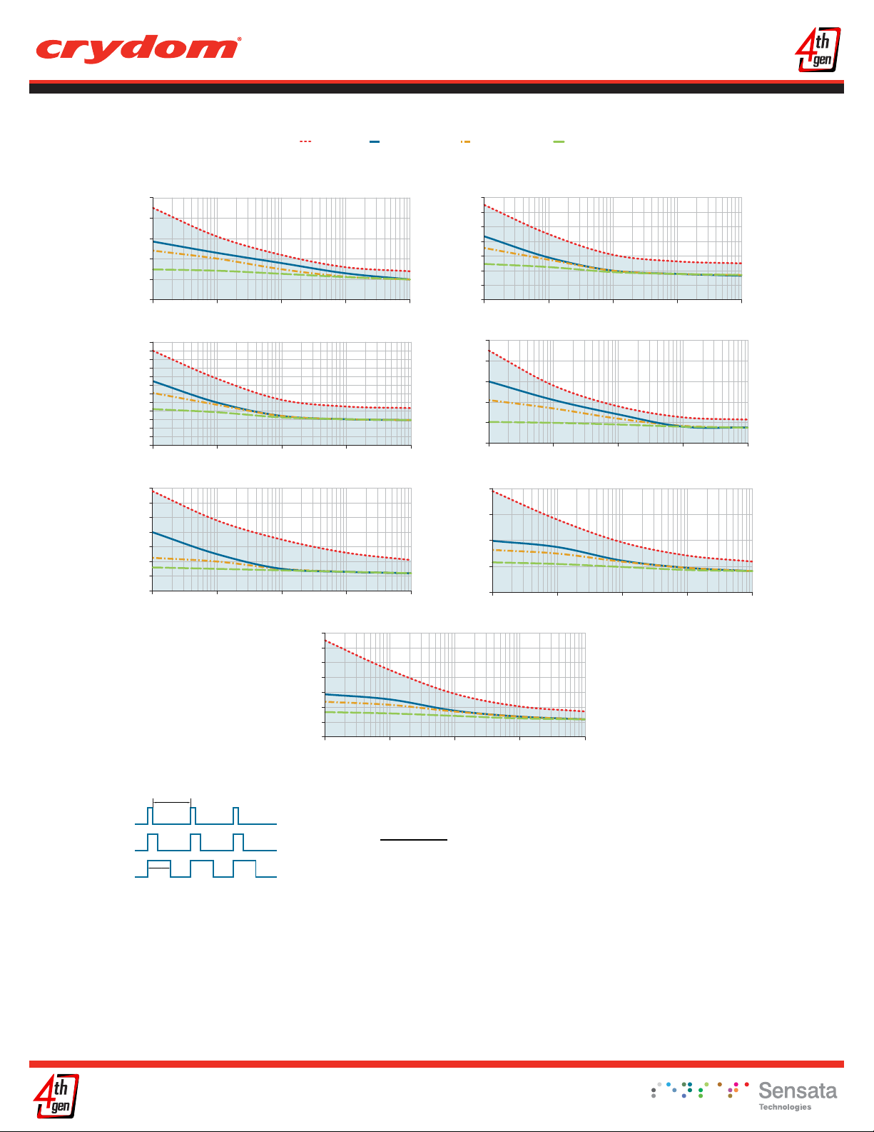
SURGE CURRENT INFORMATION
50
40
30
20
10
Surge Current (Amp)
0
0.1 1 10 100 1000
240
220
200
180
160
140
120
100
80
60
Surge Current (Amp)
40
20
0
0.1 1 10 100 1000
70
60
50
40
30
20
Surge Current (Amp)
10
0
0.1 1 10 100 1000
D2D07L
Surge Duration (msec)
D2D40L
Surge Duration (msec)
D4D12L
Surge Duration (msec)
Single Pulse (i)
70
60
50
40
30
20
Surge Current (Amp)
10
0
0.1 1 10 100 1000
Duty Factor (10%) (ii)
D5D10L
Surge Duration (msec)
Duty Factor (20%) (ii)
70
60
50
40
30
20
Surge Current (Amp)
10
0
0.1 1 10 100 1000
50
40
30
20
10
Surge Current (Amp)
0
0.1 1 10 100 1000
40
30
20
10
Surge Current (Amp)
0
0.1 1 10 100 1000
Duty Factor (50%) (ii)
D2D12L
Surge Duration (msec)
D4D07L
Surge Duration (msec)
D5D07L
Surge Duration (msec)
Duty Factor 10%
Duty Factor 20%
Duty Factor 50%
Pulse
Wide
Period
For Pulse Wide Modulation applications select
the curve according duty factor and pulse duration as following.
Duty Factor =
(i) for Single Surge Pulse Tc=40°C ;Tj 175°C
(ii) for Repetitive Surge Pulse Tc=40°C ;Tj 130°C
Pulse Wide
Period
Copyright © 2016 Crydom Inc. Specifications subject to change without notice.
x100 (%)
Page 5

THERMAL DERATE INFORMATION
(iii) SSR metal base plate acting as heat sink, it must be exposed to free ambient air.
Panel Mount
Datasheet
D1D07L
5°C/W
7
6
5
4
3
2
1
Load Current (Amps)
0
20 30 40 50 60 70 80 90 100
Ambient Temperature (ºC)
No Heat Sink(iii)
D1D40L
1°C/W
40
30
20
10
Load Current (Amps)
0
20 30 40 50 60 70 80 90 100
Ambient Temperature (ºC)
3°C/W
5°C/W
D2D40L
0.7°C/W
40
30
20
10
Load Current (Amps)
0
20 30 40 50 60 70 80 90 100
Ambient Temperature (ºC)
1.5°C/W
5°C/W
D1D12L
3°C/W
12
8
4
Load Current (Amps)
0
20 30 40 50 60 70 80 90 100
5°C/W
Ambient Temperature (ºC)
No Heat Sink
D2D07L
3°C/W
7
6
5
4
3
2
Load Current (Amps)
1
0
20 30 40 50 60 70 80 90 100
5°C/W
Ambient Temperature (ºC)
No Heat Sink
D4D07L
2°C/W
7
6
5
4
3
2
Load Current (Amps)
1
0
20 30 40 50 60 70 80 90 100
3°C/W
Ambient Temperature (ºC)
No Heat Sink
D1D20L
(iii)
20
15
10
Load Current (Amps)
2°C/W
5
0
20 30 40 50 60 70 80 90 100
3°C/W
Ambient Temperature (ºC)
No Heat Sink
(iii)
D2D12L
(iii)
Load Current (Amps)
3°C/W
12
10
8
6
4
2
0
20 30 40 50 60 70 80 90 100
5°C/W
Ambient Temperature (ºC)
No Heat Sink
(iii)
D4D12L
(iii)
12
10
8
6
4
2
Load Current (Amps)
0
20 30 40 50 60 70 80 90 100
1°C/W
2°C/W
Ambient Temperature (ºC)
5ºC/W
D5D07L
1°C/W
7
6
5
4
3
2
Load Current (Amps)
1
0
20 30 40 50 60 70 80 90 100
Ambient Temperature (ºC)
3°C/W
5ºC/W
Copyright © 2016 Crydom Inc. Specifications subject to change without notice.
D5D10L
0.7°C/W
10
8
6
4
2
Load Current (Amps)
0
20 30 40 50 60 70 80 90 100
Ambient Temperature (ºC)
2°C/W
5°C/W
Page 6

AGENCY APPROVALS
Agency Approvals
EN60950-1: Meets the requirements of sections1.5: 1,7: 2.9: 2.10.5.3: 4.2: 4.5: 4.7:
IEC 61000-4-2 Electrostatic Discharge Level 3
IEC 61000-4-4 Electrically Fast Transients Level 3
IEC 61000-4-5 Electrical Surges Level 3
E116950
ACCESORIES
Panel Mount
Datasheet
New Accessories!
Protective Cover & Hardware Kits
Protective Cover
Part number: KS101
Clear plastic cover compatible with all new
S1 designs. Safety covers provide added
protection from electric shock when
installing or checking equipment.
Hardware Kit
Part number: HK4
Bag with 2 square brass accessories and 2
screw 8-32 x 5/8 for output. Used to mount
TMR1 lug terminals.
Cover Hardware
Kit
KS101 HK1
HK4
Recommended Accessories
Heat Sink
Part No.
HS501DR
HS301 / HS301DR
HS251
HS201 / HS201DR
HS202 / HS202DR
HS172
HS151 / HS151DR
HS122 / HS122DR
HS103 / HS103DR
HS101
HS073
HS072
HS053
HS033
HS023
Thermal Resistance
[ºC/W]
5.0
3.0
2.5
2.0
2.0
1.7
1.5
1.2
1.0
1.0
0.7
0.7
0.5
0.36
0.25
Lug Terminal Thermal Pad
TRM1
TRM6
HSP-1
HSP-2
Copyright © 2016 Crydom Inc. Specifications subject to change without notice.
Rev. 031516
Page 7

Panel Mount
Datasheet
DANGER / PELIGRO / DANGER /GEFAHR / PERICOLO / 危险
HAZARD OF
ELECTRIC
SHOCK,
EXPLOSION,
OR ARC FLASH.
• Disconnect all
power before
installing or
working with
this equipment.
• Verify all
connections
and replace all
covers before
turning on
power.
Failure to follow
these
instructions will
result in death
or serious injury.
RIESGO DE
DESCARGA
ELECTRICA O
EXPLOSION.
• Desconectar
todos los
suministros de
energia a este
equipo antes
de trabajar
con este equipo.
• Verificar todas
las
conexiones
y colocar todas
las
tapas antes
de energizer
el equipo.
El
incumplimiento
de estas
instrucciones
puede provocar
la muerte o
lesiones serias.
RISQUE DE
DESCHARGE
ELECTRIQUE
OU EXPLOSION
• Eteindre
toutes les
sources
d'énergie de
cet appareil
avant de
travailler
dessus de cet
appareil
• Vérifier tous
connections, et
remettre tous
couverts en
olace avant de
mettre sous
De non-suivi de
ces instructions
provoquera la
mort ou des
lésions sérieuses
sérieuses.
GEFAHR EINES
ELEKTRISCHE
N SCHLAGES
ODER EINER
EXPLOSION.
• Stellen Sie
jeglichen
St
rom ab, der
dieses Gerät
versorgt, bevor
Sie an dem
Gerät Arbeiten
durchführen
• Vor dem
Drehen auf
Energie alle
Anschlüsse
überprüfen
und alle
Abdeckungen
ersetzen.
Unterlassung
dieser
Anweisungen
können zum
Tode oder zu
schweren
Verletzungen
führen.
RISCHIO DI
SCOSSA
ELETTRICA O
DELL’ESPLOSIONE.
• Spenga tutta
l'alimentazione
che fornisce
questa
apparecchiatura
prima di lavorare
a questa
apparecchiatura
• Verificare tutti
i collegamenti
e sostituire
utte le coperture
t
prima
dell’accensione
L'omissione di
queste istruzioni
provocherà la
morte o
lesioni serie
存在电击、
爆炸或电弧
闪烁危险
•
在操作此设
备之前请先
关闭电源。
若不遵守这些说明,
可能会导致严重的
人身伤害甚至死亡。
WARNING / AVERTISSEMENT / WARNUNG /ADVERTENCIA / AVVERTENZA / 警告
RISK OF MATERIAL DAMAGE AND HOT
ENCLOSURE
• The product's side panels may be hot, allow
the product to cool before touching.
• Follow proper mounting instructions including
torque values.
• Do not allow liquids or foreign objects to enter
this product.
Failure to follow these instructions can result in
serious injury, or equipment damage.
RIESGO DE DAÑOS MATERIALES Y DE
SOBRECALENTAMIENTO DE LA UNIDAD
• Los paneles laterales del producto pueden
estar calientes. Esperar que el producto se
enfríe antes de tocarlo.
• Respetar las instrucciones de montaje, y en
particular los pares de apretado.
• No dejar que penetren líquidos o cuerpos
extraños en el producto.
Si no se respetan estas precauciones pueden
producirse graves lesiones, daños materiales.
RISQUE DE DOMMAGE MATERIEL ET DE
SURCHAUFFE DU BOITIER
• Les panneaux latéraux du produit peuvent être
chauds. Laisser le produit refroidir avant de le
toucher.
• Respecter les consignes de montage, et
notamment les couples de serrage.
• Ne pas laisser pénétrer de liquide ni de corps
étrangers à l'intérieur du produit.
Le non-respect de cette directive peut entraîner,
des lésions corporelles graves ou des
dommages matériels.
RISCHIO DI DANNI MATERIALI E D'INVOLUCRO
CALDO
• I pannelli laterali dell'apparecchio possono
scottare; lasciar quindi raffreddare il prodotto
prima di toccarlo.
• Seguire le istruzioni di montaggio corrette.
• Non far entrare liquidi o oggetti estranei in questo
apparecchio.
La mancata osservanza di questa precauzione può
causare gravi rischi per l'incolumità personale o
danni alle apparecchiature.
GEFAHR VON MATERIALSCHÄDEN UND
GEHÄUSEERHITZUNG
• Die Seitenwände können heiß sein. Lassen Sie
das Produkt abkühlen, bevor Sie es berühren.
• Beachten Sie die Montageanweisungen,
• Führen Sie keine Flüssigkeiten oder
Fremdkörper in das Produkt ein.
Die Nichtbeachtung dieser Anweisung kann
Körperverletzung oder Materialschäden
zur Folge haben.
材料损坏和高温外壳的危险性
• 产品的一侧面板可能很热,在其冷却前请
不要触碰。
• 遵照正确的安装说明,包括扭矩值。
• 请勿让液体及其他异物进入本产品。
如不能正确执行这些操作说明,
极有可能造成严重人体伤害或者设备的损坏。
Copyright © 2016 Crydom Inc. Specifications subject to change without notice.
Page 8
Panel Mount
Datasheet
ANNEX - ENVIROMENTAL INFORMATION
The environmental information disclosed in this annex including the EIP Pollution logo are in compliance with People’s Republic of China
Electronic Industry Standard SJ/T11364 – 2006, Marking for Control of Pollution Caused by Electronic Information Products.
Part
Name
Semiconductor die
Solder
Toxic or hazardous Substance and Elements
Lead Mercury Cadmium Hexavalent Polybrominated Polybrominated
(Pb) (Hg) (Cd)
Chromium
(Cr (VI))
biphenyls
(PBB)
diphenyl ethers
(PBDE)
50
Copyright © 2016 Crydom Inc. Specifications subject to change without notice.
 Loading...