


CruzPro
MaxDS110
Multifunction Depth/Speed
Instrument
Page 1

2008 CruzPro Ltd. MaxDS110 Manual Ver. AD
http://www.cruzpro.com Made in New Zealand
Page 2

Table of Contents
Introduction . . . . . . . . . . . . . . . . . . . . . . . . . . . . 5
Installation and Wiring . . . . . . . . . . . . . . . . . . . 7
Operation of the MaxDS110 . . . . . . . . . . 9
Key Functions . . . . . . . . . . . . . . . . . . . . . . . . . . . 9
Turning Power ON/OFF . . . . . . . . . . . . . . . . . . 9
Changing and Controlling Backlight Intensity . . . . . . . 9
Selecting a Display Configuration . . . . . . . . . 9
Summary of Display Configurations 1-16 . . . . . . . . . 10
Turning Alarms ON/OFF . . . . . . . . . . . . . . . . . 16
Setting High and Low Alarm Values . . . . . . . . . . . . . . 16
Setting/Starting Clock/Time-Of-Day Alarms/Race Timers . . 17
Calibrating a Data Source . . . . . . . . . . . . . . . . . 19
Setting Display Damping . . . . . . . . . . . . . . . . 20
Setting Units of Measure . . . . . . . . . . . . . . . . 21
Setting Keel Offset . . . . . . . . . . . . . . . . 22
Clear Trip Distance and Trip Time . . . . . . . . . 22
Appendix A -
Appendix B -
Appendix C -
Appendix D -
Appendix E -
Appendix F - Critical Background Alarm Functions
Appendix G - Key Function Summary . . . . . . . . . 31
Appendix H - NMEA 0183 Sentences . . . . . . . . . 34
Appendix I - Display Firmware Version and Serial No. . . 35
Appendix J - Error Codes . . . . . . . . . . . . . . . 36
Index - . . . . . . . . . . . . . . . . . . . . . . . . 37
Other CruzPro Products . . . . . . . . . . . . . . . . . . . . 40
Specifications . . . . . . . . . . . . . . .
Packing List . . . . . . . . . . . . . . .
Optional Items . . . . . . . . . . . . . . .
Typical Setup . . . . . . . . . . . . . . .
Important Notes and Warnings . . . . . . .
. . . . .
Page 3
23
24
25
26
28
30

CruzPro is a trademark of CruzPro Ltd.
Page 4

Introduction
The MaxDS110 multifunction depth/speed instrument will
simultaneously display three sets of data on three digital displays.
Depth, boat speed, sea water temperature, trip and total logs, race
timers, time-of-day, elapsed trip time and battery voltage can be
displayed in a variety of different formats. High and Low alarms can
be set for Depth (Deep and Shallow), boat speed, water temperature
and battery voltage. Eight (8) different Time-Of-Day alarms can be
set to remind you of important radio schedules, weather FAXes, etc.
The two race timers can be independently set to any value from 1 to
60 minutes.
A keel offset can be programmed to provide the depth of the water
under the keel. Variable display damping (filtering) can be selected
for both depth and boat speed. You can switch between sixteen
different predefined display configurations with the front panel
keys. Changes are automatically saved to a nonvolatile memory.
You can select from five backlight levels (including OFF) and the
backlights can be externally activated. The MaxDS110 works on
both 12 and 24 VDC and outputs NMEA 0183 data sentences for
depth, boat speed, sea water temperature and battery voltage.
A variety of different optional depth and speed/temperature
transducers are available in plastic and bronze that mount on the
transom or through the hull.
Page 5

Page 6

Installation and Wiring
Before starting the installation, please read this entire section first.
Finger tighten the screws that mount the instrument bracket - It is
not necessary or recommended to use tools.
Drill a 2-1/8" (55mm) mounting hole where you desire to mount
the instrument (Figure 1).
Remove the adhesive backing protection from the bulkhead
gasket and carefully align the waterproof bulkhead gasket on the back
of the instrument.
Connect the various wires as shown in Figure 2.
Carefully check all your wiring then mount the instrument in
the hole. Use only finger tension to tighten the bracket hold-down
nuts
Figure 1 - Mounting the Instrument
Page 7
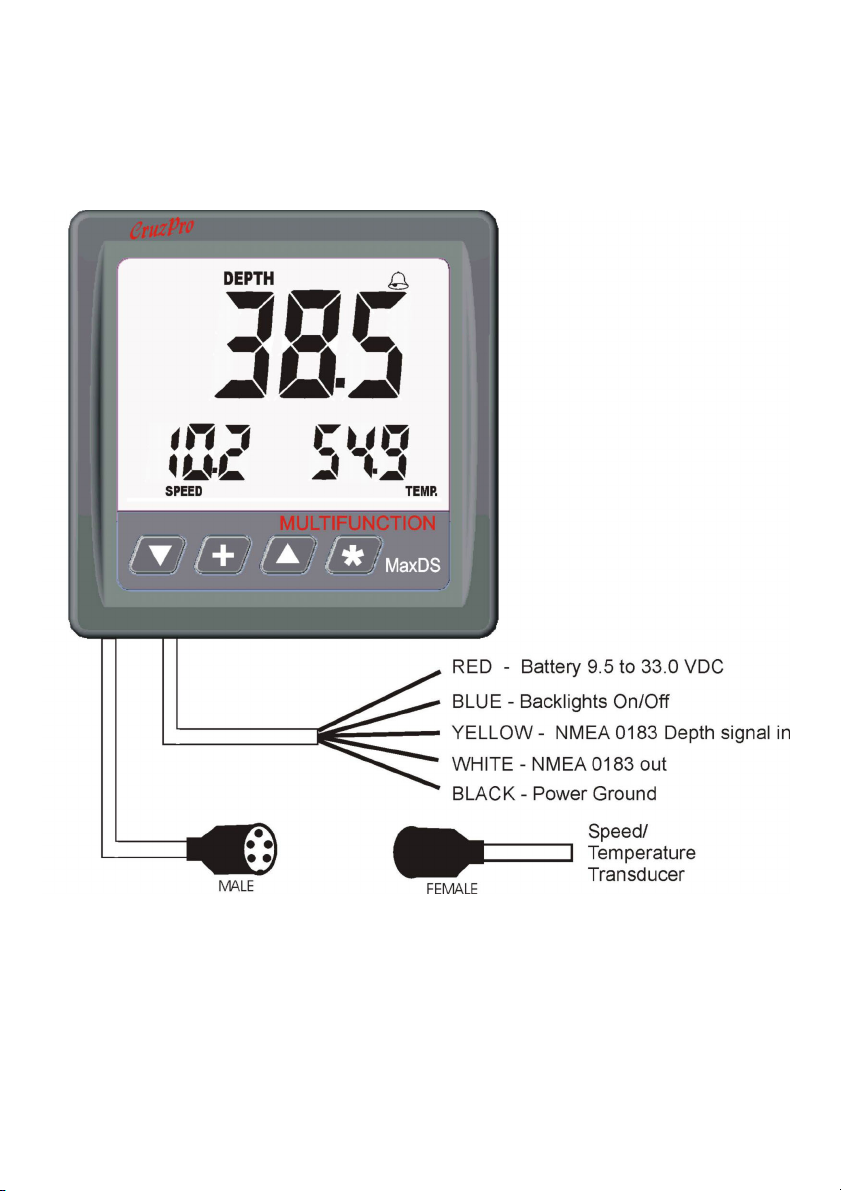
Figure 2 - MaxDS110 Wiring Diagram
Page 8

Operation of the MaxDS110
Key Functions
The t, :, s and
select display configurations, view/set alarm values and calibrate
the instrument. Changes are automatically saved to a nonvolatile
memory. A complete summary of all the possible key functions are
shown in Appendix C.
Turning Power ON/OFF
Press and hold the
display OFF - the clock will keep running. Press and hold the
for three seconds to re-enable the display. If you remove power from
the MaxDS110 the Time-Of-Day clock will have to be set again.
Changing and Controlling Backlight Intensity
Press the : key for 1/2 second to adjust the backlight level for
night viewing. Each time you press the : key for 1/2 second, the
level will get brighter 1, 2, 3, 4, OFF, 1, 2, ... etc. The backlight
ON/OFF wire provides external backlight control and this wire
must be switched to +12/24V for the backlights to work.
keys are used to select and set backlight levels,
key for five seconds to turn the MaxDS110
key
Selecting a Display Configuration
Simultaneously press both the s
and
keys to cycle between the sixteen preconfigured display
configurations. All sixteen display configurations are programmed
at time of manufacture with the sixteen configurations shown in
Figures 4 to 19.
and
keys or press both the
t
Page 9

Summary of Display Configurations 1-16
Each time you select a new display configuration the Current Display
Configuration number (in this case #1) is displayed for one second
as shown in Figure 3. After one second the display shows the data
for display configuration #1 as shown in figure 4. All 16 of the factory
default display configurations are shown in figures 4-19.
Figure 3 - Current Display
Configuration (#1)
Display #1
Display #2
Page 10
Figure 4
Display configuration 1
Depth (Display #1)
Boat Speed (Display #2)
Sea Water Temperature (Display #3)
Display #3

Figure 5
Display configuration 2
Depth
Boat Speed
Time of Day
Figure 6
Display configuration 3
Depth
Boat Speed
Battery Volts
Figure 7
Display configuration 4
Depth
Battery Volts
Sea Water Temperature
Page 11

Figure 8
Display configuration 5
Depth
Battery Volts
Time of Day
Figure 9
Display configuration 6
Boat Speed
Depth
Sea Water Temperature
Page 12
Figure 10
Display configuration 7
Boat Speed
Depth
Time of Day

Figure 11
Display configuration 8
Boat Speed
Depth
Race Timer #1 (5 minute factory default)
Figure 12
Display configuration 9
Boat Speed
Depth
Race Timer #2 (10 minute factory default)
Figure 13
Display configuration 10
Boat Speed
Depth
Elapsed Trip Time
Page 13

Figure 14
Display configuration 11
Boat Speed
Trip Log
Depth
Figure 15
Display configuration 12
Boat Speed
Trip Log
Sea Water Temperature
Page 14
Figure 16
Display configuration 13
Boat Speed
Trip Log
Time of Day

Figure 17
Display configuration 14
Boat Speed
Trip Log
Total Log
Figure 18
Display configuration 15
Sea Water Temperature
Boat Speed
Depth
Figure 19
Display configuration 16
Sea Water Temperature
Battery Volts
Depth
Page 15

Turning Alarms ON/OFF
To “arm” the alarms, press and hold the key 1/2 second. The Bell symbol
will be displayed when the alarms are “armed”. To disable the alarms press and
hold the key for 1/2 second. Any press between 1/2 and 2 seconds will
work. A press of less than 1/2 second or longer than 2 seconds will be ignored.
Setting High and Low Alarm Values
To View and/or Set the High Alarm value for any of the three current displays,
press and hold the key for ten seconds (until you hear a long beep). To
View and/or Set the Low Alarm value for any of the displays, press and hold the
key for ten seconds. The alarm value, display identifier (1, 2 or 3) and the
word “HiAL” or “LoAL” will be displayed as shown in Figure 20. Quick press
the key to select the desired display (1, 2, or 3). Press and hold the or
keys to change the alarm value. Press the key for 1 second (until the long
beep) to accept the new alarm value, save it to memory and exit the Alarm
Editor mode.
Figure 20 - Alarm Editor
Editing the Hi alarm
for display #3
To prevent confusion, the High and Low alarm values are unique for each Data
Source (Depth, Speed or Temperature, etc.). For example, if you change the
high alarm value for Depth in one display configuration, then the high alarm value
for Depth will automatically change for each display configuration where Depth
is displayed.
Page 16

Be sure to read the warnings about alarms in the Important Notes and
Warnings section about which Data Sources and conditions will sound an
audible alarm.
Setting/Starting Clock/Time-Of-Day Alarms/Race Timers
Press and hold both the and keys for ten seconds (until you hear a long
beep) to view and/or set the clock, time-of-day alarms and Race Timer1/Race
Timer2. You will see the display shown in Figure 21. The Hours will blink
showing which is being changed. Press the
key to switch between changing
the Hours or Minutes. Press (or hold )
the and keys to change the value.
Press the key to cycle through the
eight Time of Day alarms and Race Timers. Press the + key for 1 seconds
when you are done to save the results
to memory.
Figure 21 - Clock/Alarm Editor
Setting Time-Of-Day Clock
Figure 22 shows what you will see when
setting the Time-Of-Day alarms. These
are set the same way as the clock.
Press the + key for 1 seconds when
you are done to save the results to
memory.
Figure 22 - Clock/Alarm Editor
Setting the eight Time-Of-Day
Alarms
Page 17

Figure 23 shows what you will see when setting Race Timer 2. The race timers
are set the same way as the clock. Only the minutes can be set for the race
timers. Press the + key for 1 second when you are done to save the results to
memory.
To start Race Timer 1 quick press both the and keys. To start Race Timer
2 quick press both the and keys. You do not have to be viewing the race
timers for them to start/run/stop - they will work in the background. The race
timers will start counting down from their assigned values and beep as each
minute is counted down. When the race timers reach 10 seconds each second
will be sounded off with a short beep. When the race timers reach zero you will
hear a long beep.
In order to prevent confusion, only one race timer can be running. Starting Race
Timer 2 will stop Race Timer1 and vice-versa. Once a race timer has been
started it can also be stopped the same way. Restarting the race timers will
cause them to reset and start from their original values; not from where they were
stopped.
Page 18
Figure 23 - Setting Race Timer 2

Calibrating a Data Source
Calibrating the displayed data is possible for boat speed, sea water temperature,
battery voltage and the clock. Press and hold the and
keys for ten sec-
onds to enter the Calibration Editor (until you hear a long beep). The data
source value, display identifier (1, 2 or 3) and the word “CAL” will be displayed
as shown in Figure 24. Quick press the key to select the desired display (1,
2 or 3). Press and hold the or keys to change the calibration. Press the
key for 1 second (until the long beep) to accept the new value, save it to
memory and leave the Calibration Editor mode.
Figure 24 - Calibration Editor
Editing the calibration for the Data
Source shown on digital display #2
When calibrating the Time-Of-Day clock a calibration value between 0 and 100
(nominal value is 50 ) will be shown on Display #1 and the time of day shown on
Display #3. Increase the Clock Calibration value to speed up the clock, decrease the Clock Calibration value to slow down the clock. Increasing the
Clock Calibration value by one will increase the clock speed by 1 second per
day. Decreasing the Clock Calibration value by one will decrease the clock
speed by 1 second per day.
Page 19

If the selected data source cannot be calibrated (such as Elapsed Trip Time)
then “---” will be displayed for the Data Source value as shown here.
Figure 25 - Calibration Editor
Sample display when attempting to
calibrate a Data Source that cannot
be calibrated.
Setting Display Damping
It is possible to slow down how fast the numbers on the display change by
adding “Display Damping” to
the Boat Speed and/or Depth displays.
Filter values between 0 (No damping) and 250 (Extremely slow
response) are allowed.
Press and hold both the and
keys for ten seconds to enter the Display
Damping Editor (until you hear a long beep). The filter value, display identifier
(1, 2, 3) and the word “Filt” will be displayed as shown in Figure 26. Quick
press the key to select the desired display identifier (1, 2, 3). Press and hold
the and keys to change the calibration value. Press the key for 1
second (until the long beep) to accept the new value, save it to memory and exit
the Display Damping Editor mode.
If the selected data source cannot be filtered (such as Elapsed Trip Time) then
“---” will be displayed for the Filter value.
Page 20

Figure 26 - Display Damping Editor
Setting the Damping Value to “7” for the
Data Source shown on digital display #3
Setting Units of Measure
Units of Measure are factory set to Feet, Knots and Degrees F. The clock is set
to display in 12 hour format. Press and hold both the and
keys for ten
seconds (until you hear a long beep) to change units to Meters/Fathoms, Miles
Per Hour (MPH), Km/Hr, Degrees C and/or to use 24 hour format for the
clock. After the long beep the display shown in Figure 27 will be shown. Press
the
key to select between Depth, Speed, Degrees or Clock. Press the
or keys to change the units. Press
the key for 1 second (until the long
beep) to accept the new value, save
it to memory and exit the Setting
Units of Measure mode.
Figure 27 - Setting Units of
Measure
Setting the Depth units to “Feet”
Page 21

Setting Keel Offset
You can enter a Keel Offset value between -50.0 and +50.0 Feet/Meters or
Fathoms to modify the depth display. Entering a negative number enables you
to display the depth below the keel instead of the depth below the transducer.
Entering a positive number enables you to display the actual water depth below
the surface instead of the depth below the transducer.
The factory default Keel Offset is 0.0. Press and hold both the
and keys
for ten seconds (until you hear a long beep) to view/set the Keel Offset value.
After the long beep the display shown in Figure 28 will be shown. Press and
hold the and keys to change the value. Press the key for 1 second
(until the long beep) to accept the new value, save it to memory and exit the
Keel Offset Editor Editor mode. If you change untis of measure between Feet,
Meters and Fathoms, you will need to reset the Keel Offset (if non-zero) so set
the Unit of Measure for depth first, before entering a Keel Offset.
Figure 28 - Keel Offset Editor
Sample display when changing the
Keel Offset
Clearing Trip Distance and Trip Time
Press and hold the key for 10 seconds (until you hear a long beep) to clear
Trip Distance and Elapsed Trip Time to zero.
Page 22

Appendix A - Specifications
Power supply: 12/24 VDC (9.5 to 33.0), 0.10 A nominal
Operating temperature: 32 to 122 F ( 0 to 50 C)
Size:
Display: LCD, 3 digital, 16 different configurations
Backlighting: 5 levels (including OFF), plus external backlight
Alarms: Individual high and low alarms for each of the 3 dis-
Data Sources/Inputs:
Outputs: NMEA 0183 depth, speed, sea water temperature and
4.3" x 4.3” x 3.5” deep (110 x 110 x 89 mm).
On/Off control.
plays and 8 Time of Day alarms (Fax & radio schedules,
etc.).
Battery Voltage (To 0.01 VDC)
Boat speed (To 0.01 MPH, Knots)
Clock (12/24 hour format)
Sea water temperature
Depth (from NMEA 0183 $SDDBT sentence)
Race Timers (2)
Time of Day Alarms (8)
Trip Log
Total Log
Elapsed Trip Time
battery voltage data.
Memory: Nonvolatile memory for alarms, current display
configuration, calibrations, backlight levels, etc.
Data retention for ten years without power.
Page 23

Appendix B - Packing List
The MaxDS110 package is supplied with the following items:
1) MaxDS110 instrument.
2) Dust/rain cover.
3) Closed cell foam waterproof bulkhead gasket (adhesive one side).
4) Printed user manual.
5) Warranty card.
Page 24

Appendix C - Optional Items
A number of different transducer options are available for the MaxDS110:
Depth Transducer Options:
1) ATB120A - 450 ft bronze thru-hull ACTIVE NMEA 0183 transducer.
2) ATB120B - 1000 foot bronze thru-hull ACTIVE depth NMEA 0183
transducer.
3) ATT120A - 450 foot transom mount ACTIVE depth NMEA 0183
transducer.
4) ATT120B - 1000 foot transom mount ACTIVE depth NMEA 0183
transducer.
5) ATU120A 450 foot plastic thru-hull mount ACTIVE depth NMEA 0183
transducer.
6) ATU120B 1000 foot plastic thru-hull mount ACTIVE depth NMEA 0183
transducer.
Speed/Temperature Transducer Options:
1) THST-2 Retractable Plastic Thru-Hull Speed/Temp Transducer with 30'
cable and 5 pin Fuji connector.
2) THST-3 Retractable Bronze Thru-Hull Speed/Temp Transducer with
30' cable & plug with 5 pin Fuji connector.
3) TMST-2 Transom Mount Speed/Temp Transducer with 25' cable with 5 pin
Fuji connector.
Page 25

Appendix D - Typical Setup
Page 26

Page 27

Appendix E - Important Notes and Warnings
1) The front of the MaxDS110 is splash proof. The back is not sealed and
must be protected from water.
2) The nonvolatile memory in the MaxDS110 will retain data for a minimum of
10 years without power.
3) The lines connecting to the +12/24V Battery should be protected from
shorts by placing a 5 amp fuse near the battery side of the connection.
4) If you want an alarm to sound for a particular Data Source:
a) The alarms must be “armed” (i.e. the Bell symbol must be lit).
b) The Data Source value must fall outside the Low or High Alarm limits.
c) Only the following Data Sources will activate the alarm:
1) Data Sources being viewed on the display (fast alarm beep)
2) Critical background alarm functions (See list in Appendix E).
5) The displayed value will show “----” or “---” if that Data Source cannot be
displayed or modified. For example - while you can “Calibrate” Boat Speed
you cannot “Calibrate” the total log or “Calibrate” a Elapsed Trip Time. While
you can change “Display Damping” on Boat Speed or “Depth” fluctuations, you
cannot change “Display Damping” on the total log. “---” or “----” will be also
be shown if the displayed number is larger than will fit on the display (e.g. the four
digit number 1734 will not fit on 3 digit display).
6) The default Units of Measure are Feet, Knots, Nautical Miles and degrees
Fahrenheit. Once a unit of measure is selected/changed it will be used for all
Data Sources using that unit (i.e. deg F for all temperature displays).
7) When Units of Measure are changed, the alarm values are not modified.
You must set the Units of Measure first, then set the alarm values or change
alarms values manually if you change the Units of Measure.
8) Turning Power ON/OFF. The MaxDS110 draws very little power and is
intended to have power ON at all times. Press and hold the key to turn the
MaxDS110 display OFF. The clock will keep running. Press and hold the
Page 28

key again to enable the display. The Time-Of-Day clock will have to be set
again if you remove power to the MaxDS110 but all other data is saved to a
nonvolatile memory and not lost.
9) After settings are changed it can take up to 30 seconds to save the data to
the nonvolatile memory. If power is removed from the MaxDS110 during this
time the changes may not be saved to memory and the older settings will be used
when power is reapplied.
10) Both High and Low alarms for Depth data can only be set in full units (i.e. full
Feet or full Meters, not tenths).
11) When using the t and s keys to change a value, holding them down will
cause the value to scroll fast after three seconds and very fast after ten seconds.
Page 29

Appendix F - Critical Background Alarm Functions
In addition to sounding the alarms for the functions currently being displayed, the
MaxDS110 always monitors the following “Critical” functions in the background
regardless of what is being displayed on the screen. The alarm will sound only
if the alarms are armed, however.
Priority Alarm Code Function
1 27 Depth
2 18 Battery Volts
3 9 Boat Speed
4 15 Time-Of-Day alarms (Up to 8 different)
If one of these critical functions go outside the alarm limits a slow alarm signal will
sound and the alarm bell icon will blink. Quick press the
and view the alarm code for which alarm has been breached. The display will vary
depending on the function as shown in the following examples. Quick press the
key again to view the previous display configuration. The alarm bell icon will
continue to blink until you disarm the alarms. If multiple critical alarms are
breached the one with the highest priority will be displayed. The critical alarm
function and value stay in memory until cleared.
key to silence the alarm
You can continue to toggle between viewing the critical alarm function display and
the current display configuration. Once the alarms have been disabled the critical
alarm function memory is cleared and viewing is disabled.
Sample Critical Alarm Screen
Sample display when Depth alarm
has been breached in the background
Page 30

Appendix G - Key Function Summary
In normal display mode
Keys Secs Function
0.1 Scroll DOWN display configurations
0.1 Scroll UP display configurations
0.1 Toggle between view Critical Alarms screen and
view current display configuration .
0.1 Start/Stop Race Timer #1
0.1 Start/Stop Race Timer #2
0.1 Display Version and Serial Number for 5 seconds
0.5 Disable Alarms (Turns off BELL symbol)
0.5 Scroll UP through 5 backlight levels
0.5 Enable alarms (Turns on BELL symbol)
5 Turn Power OFF/ON (Disable/Enable Display)
Keys Secs Function
10 Enter “Set Low Alarm Values” Mode
10 Clear Trip Distance and Elapsed Trip Time
10 Enter “Set High Alarm Values” Mode
10 Enter “Set Display Damping” Mode
10 Enter “Calibrate Display” Mode
10 Enter “Set Units of Measure” Mode
10 Enter “Set Keel Offset” Mode
10 Enter “Set Time-Of-Day/Alarms/Race Timer” Mode
Page 31

In “Set Low/High Alarm Values” Mode
Keys Secs Function
0.1 Scroll through Display Number (1, 2, 3)
0.1 Decrease displayed reading (hold to go faster)
0.1 Increase displayed reading (hold to go faster)
1.0 Save new calibration value(s) to memory
In “Set Display Damping” Mode
Keys Sec. Function
0.1 Scroll through Display Number (1, 2, 3)
0.1 Decrease selected display damping (hold to go
faster)
0.1 Increase selected display damping (hold to go
faster)
1.0 Save new value(s) to nonvolatile memory
In “Calibrate Displays” Mode
Keys Secs Function
0.1 Scroll through Display Number (1, 2, 3)
0.1 Decrease displayed reading (hold to go faster)
0.1 Increase displayed reading (hold to go faster)
1.0 Save new calibration value(s) to memory
Page 32

In “Set Units of Measure” Mode
Keys Secs Function
0.1 Select Depth, Speed, Temperature or 12/24 Hr
0.1 Scroll through the possible units
0.1 Scroll through the possible units
1.0 Save new units of measure to memory
In “Set Keel Offset” Mode
Keys Secs Function
0.1 Decrease the Offset value (hold to go faster)
0.1 Increase the Offset value (hold to go faster)
1.0 Save new units of measure to memory
In “Set Time-Of-Day/Alarms/Race Timer ” Mode
Keys Secs Function
0.1 Select Time-Of-Day, Alarm1, Alarm2, etc.
0.1 Switch between setting Hours and Minutes
0.1 Decrease value (hold to go faster)
0.1 Increase value (hold to go faster)
1.0 Save new value(s) to memory
Page 33

Appendix H - NMEA 0183 Sentences
The MaxDS110 outputs NMEA 0183 serial data for use with remote data repeaters or data logging hardware. The data consists of the $IIXDR sentence
and contains data for Depth, Boat Speed, Sea Water Temperature and Battery
Voltage in that order.
A sample of the $IIXDR sentence is shown here:
$IIXDR,G,038.5,,G,10.22,,G,054.9,,G,13.83,,G,,,MaxDS110*69
Where the depth is 38.5, the boat speed is 10.22, the water temperature is 54.9
in the selected units of measure and the battery voltage is 13.83 VDC.
Page 34

Appendix I - Display Firmware Ver. and Serial Number
Quick press both the and keys to display the current Firmware Version
and the product Serial Number for five seconds.
Page 35

Appendix J - Error Codes
The internal software that runs the MaxDS110 instrument can detect and display
some software and hardware errors. A listing of those error codes and their
meaning as shown below.
0 Contents of internal nonvolatile memory are corrupted and factory defaults
are being used. Please check and set/reset all alarm values, etc.
1 Unable to communicate with micro U101 - contact dealer
2 Unable to communicate with micro U201 - contact dealer
3 Unable to communicate with micro U301 - contact dealer
4 Unable to communicate with micro U401 - contact dealer
5 Contents of nonvolatile memory corrupted and factory defaults are being
used. Please check and set/reset Total Log.
6 Supply voltage below the minimum 11.2 VDC required to update data to
the nonvolatile memory. Check power.
7 Unable to program or read nonvolatile memory - contact dealer.
8 Error reading Current Configuration Data from nonvolatile memory.
Contact dealer if unable to reprogram.
9 Not used
10 Not used
11 Not used
12 Error reading logs from nonvolatile memory - contact dealer.
13. Activation code error - contact dealer.
Page 36

Index
A
Alarm 3, 16, 23
alarm 9, 28
Alarm Code 30
Alarms 16, 31
armed 28
B
background alarm 28
Backlight 9
backlight 9
C
Calibrate 3, 18, 19, 23
calibrate 9, 20, 23
Calibrating the Time-Of-Day clock 19
Clearing Trip Distance and Trip Time Logs 22
Clock Calibration 19
critical functions 30
Critical Background Alarm 30
D
Damping 3, 20, 21, 31, 32
damping 5
Data Source 3, 19, 20, 21, 28
data source 20
Data Sources 23, 28
Display Configuration 3, 9, 10
display configuration 9, 10
E
Error Codes 36
errors 36
F
fast alarm 28
Firmware Version and Serial Number 35
Page 37

fuse 28
H
Hours and Minutes 33
K
Key Functions 3, 9
key functions 9
N
NMEA 3, 5, 34, 40
nonvolatile memory 28
nonvolatile 32
Notes and Warnings 28
O
ON/OFF 9
P
Power ON/OFF 9
S
scroll fast 29
Serial Number 35
Specifications 23
start Race Timer 18
T
Time-Of-Day 33
Turn Power OFF/ON 31
Turning Power ON/OFF 9, 28
U
Units of Measure 3, 21, 28
W
Warnings 28
Page 38

User Notes
Page 39

Other CruzPro Products
l Depthsounders/w Keel Offset, Deep/Shallow/Anchor Drag Alarms
l PC Based DSP Fishfinder for Windows98, NT, SE,XP, 2000
l Speed/Temperature/Logs
l 34 Function Multi-Function Gauge
l Digital DC Volts Gauge/w Alarms
l Digital DC Volts Gauge/w Alarms for 3 Battery Banks
l Digital Amps Gauge
l DC Volts/Amps/Amp-Hour Monitors
l AC Volts/Amps/Freq/kW Monitors
l LPG/Petrol Gas Detectors/Alarms
l Bilge Water Alarms/w Stainless Steel Water Sensor
l Intelligent Bilge Pump Controllers/w Stainless Steel Water Sensors
l Intelligent Windlass Controller/Chain Counters
l Digital Fuel Gauges & Fuel Consumption Calculator
l Digital Tank Level Gauges for 1 or 3 Tanks /w Separate Alarms
l Smart 4 step Alternator Regulator
l Marine Security System/w Reliable Intrusion Sensors
l RPM/Engine Hours/Elapsed Time Gauges/w Alarm
l Digital Engine Temperature Gauge/w Alarms
l Digital Oil Pressure Gauge/w Alarms
l Digital Temperature Gauges for 1 or 3 Areas /w Alarms
l Digital Clock/Watch/Race Timers/w 8 Alarms
l 8 and 16 Amp Light Dimmers / Motor Speed Controller
l Solar Panel Charge Controllers 6/8/9 & 20 Amps
l 4 & 8 Channel NMEA Combiners/RS-232 Convertors
l Engine/Exhaust Temp. Monitor & Digital Pyrometer
l NMEA 0183 Remote Data Repeaters/w 4 and 8 Input Channels
l High Pressure Digital Hydraulic Pressure Gauge
l Engine Hours/Elapsed Trip Time/Engine Maintenance Alarm Gauge
email: info@cruzpro.com
website: www.cruzpro.com
Page 40
 Loading...