

Page 1

Cruzbike Sofrider v2 Assembly Instructions - 3/1/2011
Cruzbike Sofrider v2 Assembly page 1 of 11
Assembly Instructions for the
Cruzbike Sofrider
These are assembly instructions only.
Please read the Cruzbike Owner’s Manual for important safety
information and riding instructions.
A Cruzbike Owners support forum is located at:
http://www.cruzbike.com/forums/
Page 2
Cruzbike Sofrider v2 Assembly Instructions - 3/1/2011
Cruzbike Sofrider v2 Assembly page 2 of 11
Read these instructions completely
before beginning assembly. There are
several safety-critical steps that we
instruct you to have performed by a
professional bike mechanic. Do not
attempt these steps yourself if you are
not appropriately skilled or experienced,
or are in any way unsure about these
steps.
Start with a clean work area and tools including
a rubber hammer, metric Allen wrenches,
Phillips screwdriver, snippe rs, utility knife, and
pliers. A light lubricant is also useful.
fig 1.
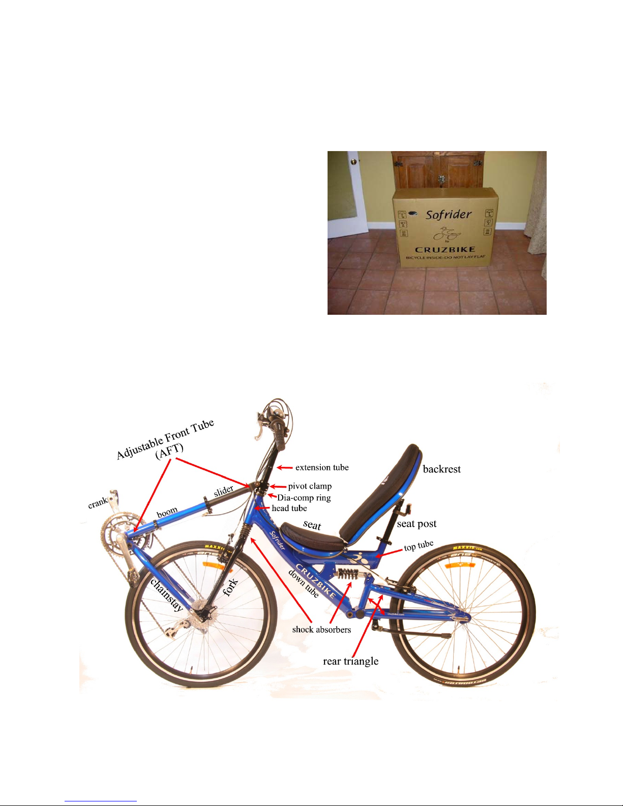
It’s a good idea to see what the finished product should look like. Below (fig. 2) is a properly
assembled Cruzbike Sofrider V2. Note the names of the basic parts of the bicycle.
fig. 2
Page 3
Cruzbike Sofrider v2 Assembly Instructions - 3/1/2011
Cruzbike Sofrider v2 Assembly page 3 of 11
Step 1:
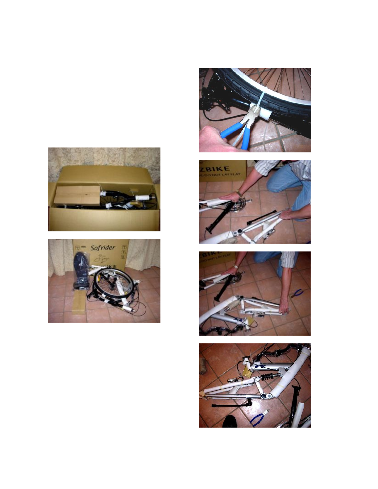
Open the box (fig. 3-4) and remove contents:
1) small box of parts,
2) seat/cushion,
3) backrest/cushion, and
4) the bicycle frame, wheels, etc., all tied
together.
(fig. 5) Snip all plastic zip ties and set the
wheels aside.
fig. 3
fig. 4
Step 2:
(fig. 6-8) Attach the rear shock absorber to the
rear triangle. Rotate the rear triangle around
and use two 5mm Allen wrenches to secure
tightly. If you don’t have a second 5 mm Allen
wrench, a 3/16” Allen wrench will work, too.
See photos below.
fig. 5
fig. 6
fig.7
fig. 8 Done.
Page 4
Cruzbike Sofrider v2 Assembly Instructions - 3/1/2011
Cruzbike Sofrider v2 Assembly page 4 of 11
Step 3:
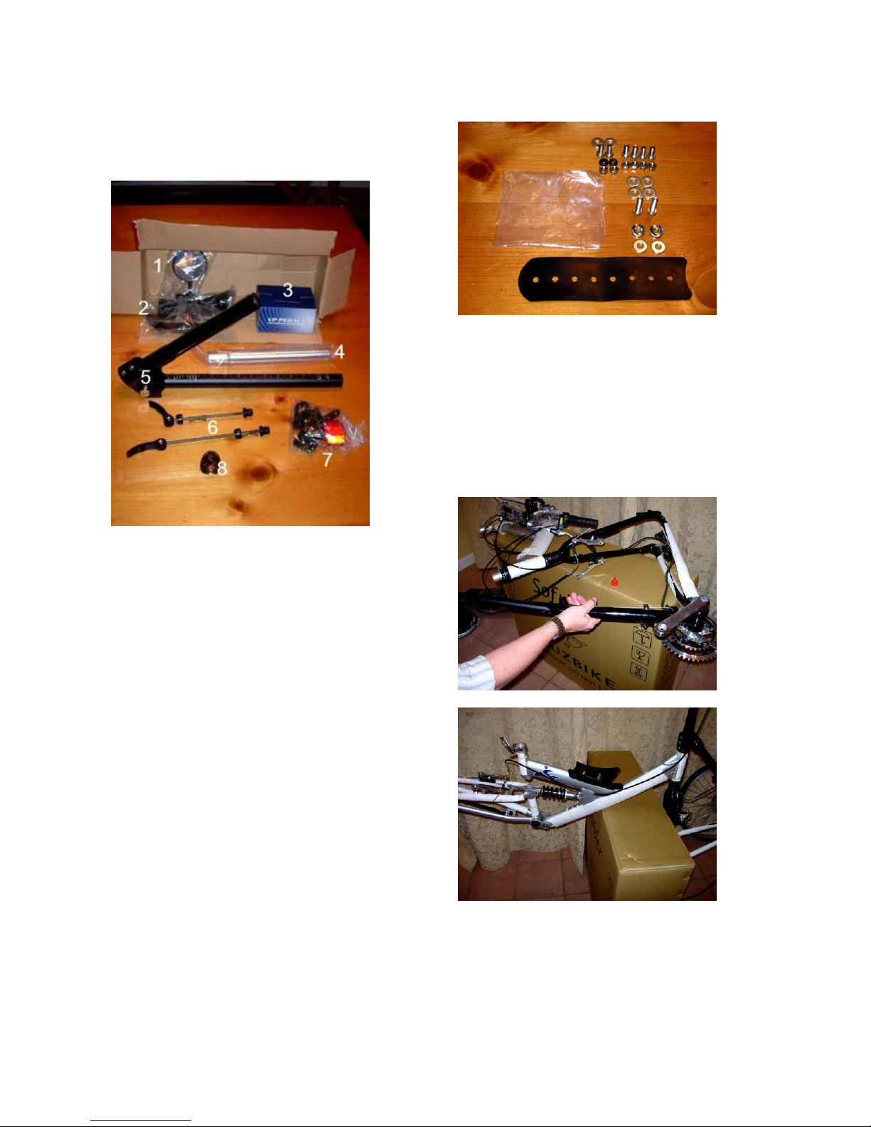
Unpack the small parts box (f ig. 9).
fig. 9
The parts box contains:
1) “bar end” rear view mirror
2) seat mount bracket and bag of bolts,
nuts, etc.
3) pedals
4) seat post
5) pivot clamp (with extension tube and
slider tube of AFT attached)
6) QR (Quick-Release) skewers for front
(long) and rear (short) wheels
7) Reflectors, etc.
8) Cruzbike Head tube badge
In the small bag (fig. 10), there are two long
bolts and two curved surface washers for
attaching the seat mount bracket to the top tube
of the frame. The rubber sheet goes between
the frame’s top tube and the bracket. Four short
bolts connect the seat to the seat mount bracket,
and two short bolts (with rubber washers)
connect the seat and backrest. More on these
later.
fig. 10
Note
These two pictures (fig. 11-12) are just to show
you different ways you can use t he b o x t o
support the bike as you assemble it. Use either,
both, or neither method as you see fit.
fig. 11
fig. 12
Page 5
Cruzbike Sofrider v2 Assembly Instructions - 3/1/2011
Cruzbike Sofrider v2 Assembly page 5 of 11
Step 4:
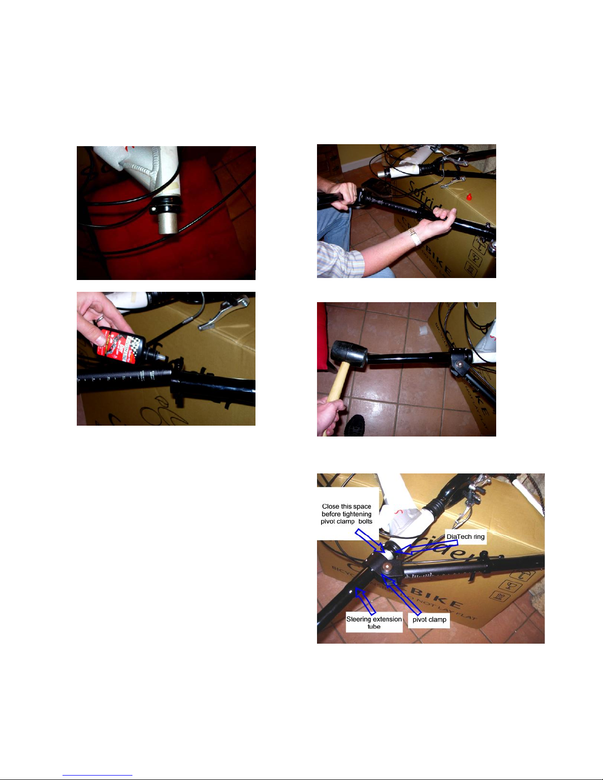
Connect the AFT and install the pivot clamp
over the fork steerer tube (f ig. 13, silver
cylinder). Attach the handlebar.
fig. 13
fig. 14
Make sure the DiaTech ring is installed on the
fork steerer tube as shown in fig. 13. Insert the
inner (slider) tube of the AFT (telescopic front
tube) into the outer tube of the AFT. You may
want to apply some light Teflon lubricant here
(fig. 14). The inner tube of the AFT has
measurement markings, w hich should face up
when the bike is upright.
Make sure the two pinch bolts of th e pivot
clamp are loose (5 mm Allen wrenc h) a n d w o rk
the pivot clamp over the end of the steerer (fig.
13). Tap the top of the Extension tube with a
rubber hammer to seat it around the steerer (see
figs. 15-17). Tighten the two pivot clamp bolts
when the pivot clamp is flush with the DiaTech
ring clamp, which is the black ring at the top of
the steerer.
Use a 5mm Allen wrench and attach handlebar
stem to top of steering extension tube, brake
levers toward the front... will fine-adjust cables
and grips later.
fig. 15
fig. 16
fig. 17
Page 6
Cruzbike Sofrider v2 Assembly Instructions - 3/1/2011
Cruzbike Sofrider v2 Assembly page 6 of 11
Step 5:
Install the seat mount bracket, seat, and
backrest.
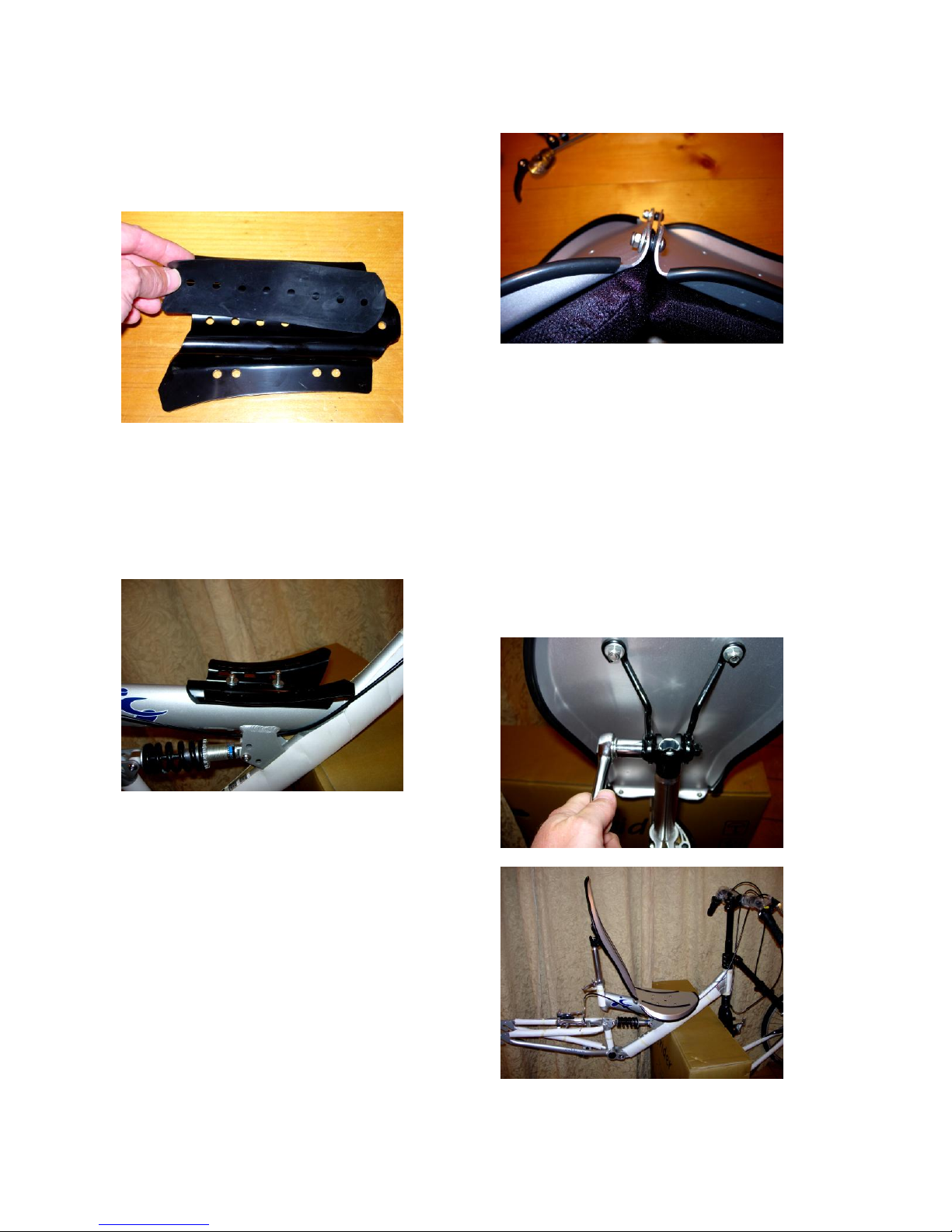
fig. 18 Seat mount bracket and rubber sheet.
The rubber sheet goes between the frame (top
tube) and bracket.
The tall end of the bracket goes toward the
front of the bike.
fig. 19
Use the two long bolts and the curved washers
to attach to frame with a 4mm Allen wrench.
The rubber sheet and bracket have 8 holes. Use
the 3
rd
and 6th holes for the bolts. Keep in mind
that, later, if you decide to mo ve the seat fore or
aft, you can move this bracket by us ing holes 2
& 5, for example, or holes 4 & 7.
Next, we need to connect the seat to the
backrest with two short bol ts with rubber
washers in- between.
fig. 20
Place the standard washer next to the nut.
Tighten with 10mm socket wrench and 4mm
Allen wrench. Remove cushions. Attach seat
to seat bracket with 4 short bolts (nuts and
washers on the bottom). The two forward-most
holes in the bracket should align with the two
forward-most holes in the seat. The seat can
also be adjusted fore or aft by aligning the holes
in the seat pan with a different set of holes in
the bracket.
Attach backrest to seat post with rubber
hammer and a 14mm socket wrench:
fig. 21 and 22 (below)
Page 7
Cruzbike Sofrider v2 Assembly Instructions - 3/1/2011
Cruzbike Sofrider v2 Assembly page 7 of 11
Adjust the angle of the backrest b y raisin g or
lowering the seat post or by sliding the back
rest clamp up or down (14mm socket wrench).
Step 6:
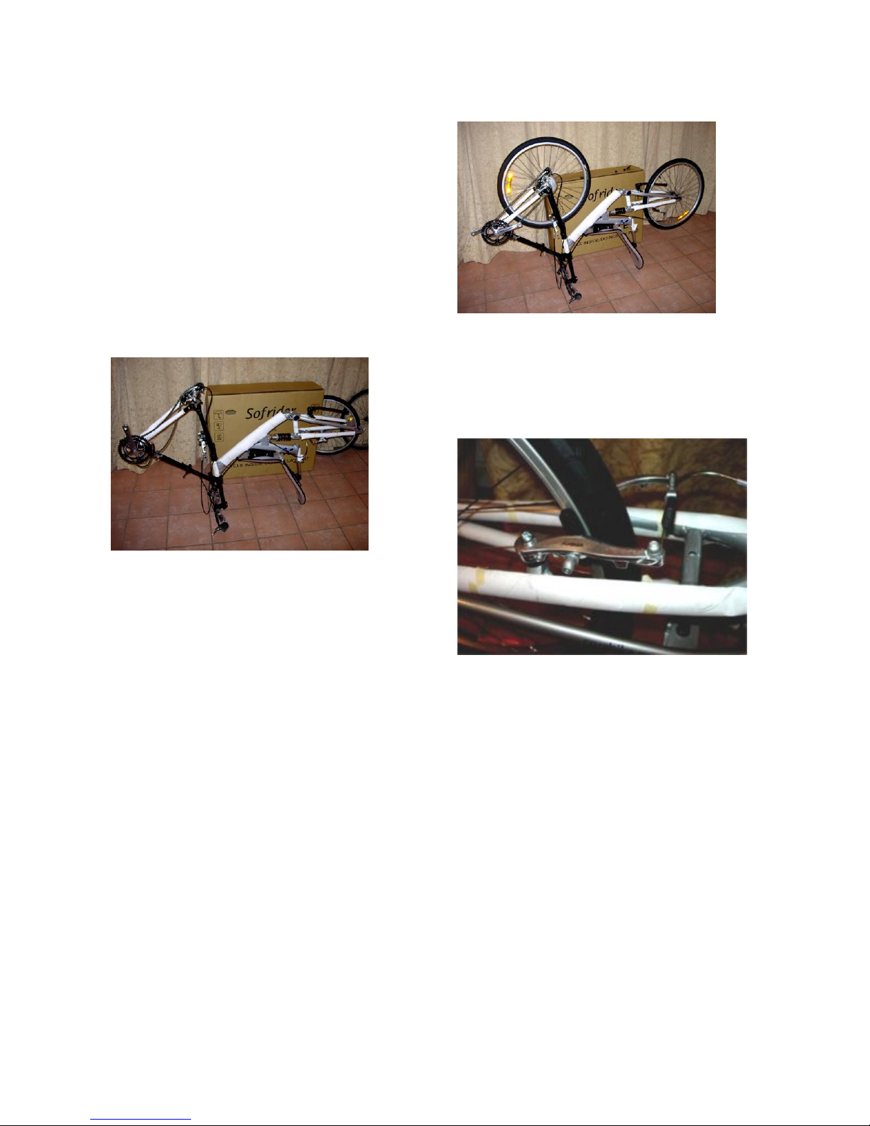
Install wheels and brakes.
Flip bike over (fig. 23). You might as well
learn now that it’s easier to flip the bike around
if you have one hand on the AFT. This keeps
the front triangle (actually a tetrahedron) from
folding back on you.
fig. 23
First, release the brakes by pulling back on the
cylindrical rubber cover and release the metal
nipple from the bracket. Insert the rear wheel,
making sure the arrow on the tire is pointing in
the direction of rotation. Place the short skewer
through the axle and lock in place (one spring
on each side of the skewer, pointy end pointing
toward the center of the hub). The front wheel
goes on with the cassette (the stack of
sprockets) on the side with the chainrings and
derailleurs. The inside loop of the cha in s h o uld
engage the cassette before dropping in the fork
slots. Once the wheel is in place lock in the
long skewer as you did the sho r t one.
fig. 24
Now you can flip the bike right-side-u p a n d
lean it against a wall to adjust the brakes.
Now you can flip the bike right-side-u p a n d
lean it against a wall to adjust the brakes.
fig. 25
First, make sure the wheel is centered in the
swing-arm – the center of the tire should line up
with the hole in the crossbar. Center the wheel
by loosening the quick release and adjusting the
axle position in the dropouts. Tighten the wheel
with the quick release, and then, adjust Vbrakes with a 5mm and 2.5mm Allen wrench.
The brakes pads should be squarely aligned on
the rims (fig 25). Clearance should be adjusted
by adjusting the cable. The 2.5mm Allen
wrench is for making the pad-t o-rim distance
for the right and left pad equal. This is a
critical step and should be done by a
professional mechanic.
Page 8
Cruzbike Sofrider v2 Assembly Instructions - 3/1/2011
Cruzbike Sofrider v2 Assembly page 8 of 11
Step 7: (optional)
Re-routing cables through the pivot clamp
tunnel. This step is optional. Some prefer to
simply use a plastic zip tie through the pivot
clamp tunnel and around the cable to secure
them neatly and out of the way of your legs.
This is a good idea, especially if you are tall.
The tunnel gets narrower as the AFT elongates.
Therefore, if you are tall (or have a long Xseam), the tunnel can get too narrow and can
pinch or cut the cable housing.
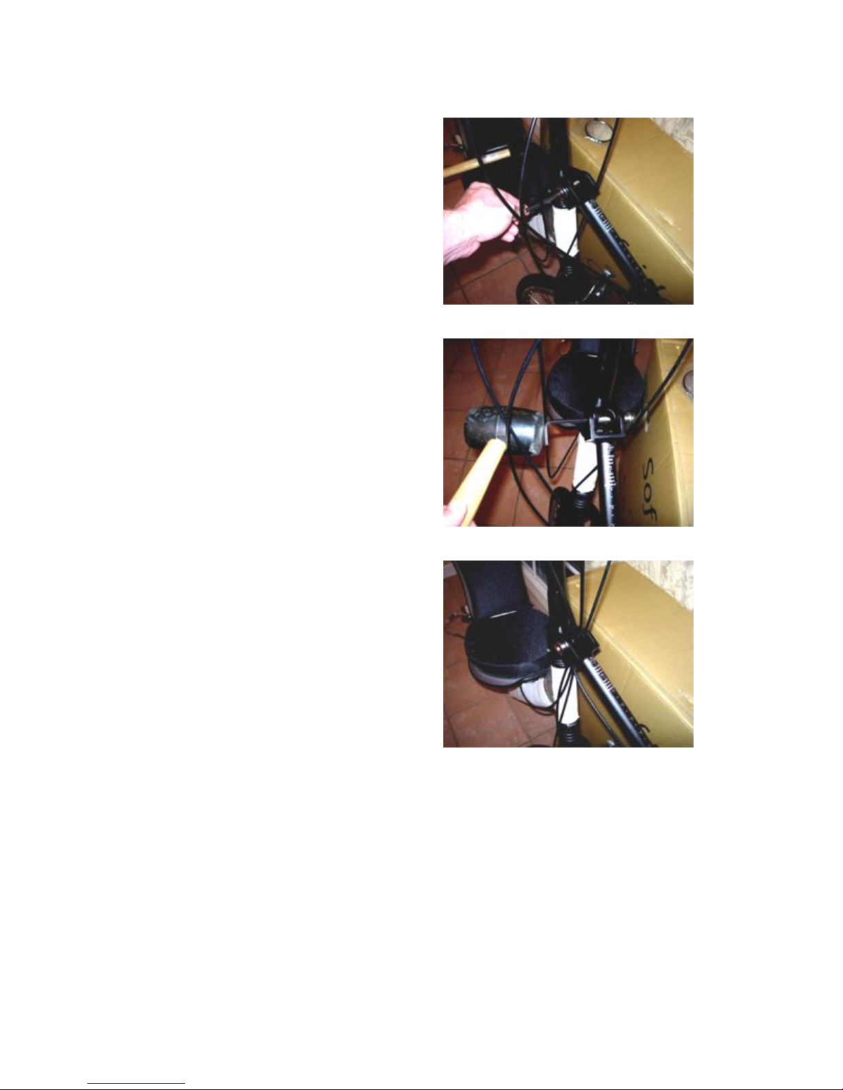
If you choose to re-route the cables through the
pivot clamp tunnel, use a 6mm Allen wrench
and remove the large steel bolt. You may need
to tap out half the bolt with a rubber hammer as
shown in the photo. Don’t disturb the brass
bushings that are recessed in the pivot clamp.
Move the now-disconnected AFT out of the
way, grab the cables and stic k them in the
tunnel, and then reattach the AFT to the pivot
clamp. See figs. 27-29.
fig. 27
fig. 28
fig. 29
Page 9
Cruzbike Sofrider v2 Assembly Instructions - 3/1/2011
Cruzbike Sofrider v2 Assembly page 9 of 11
Step 8:
Install front and rear reflectors, mirror, pedals,
and head tube badge
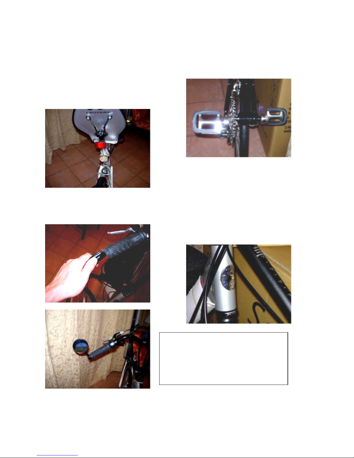
The red reflector mounts on the seatpost (fig.
30). The white one mounts on the handlebar:
fig. 30
Install mirror: use a utility knife and cut out the
end of the rubber grip on the left (or the right if
you prefer). (fig. 31-32):
fig. 31
fig. 32
The pedals are marked ‘L’ and ‘R”. The left
pedal is reverse threaded, so turn it counterclockwise to tighten:
fig. 33
Be sure to proudly “peel & stick” your
CRUZBIKE badge on the front and center of
your head tube!
fig. 34
Å Mirror: (fig 32) a good mirror is an
important accessory on ANY recumbent. We
recommend you use the Mountain Mirrycle
mirror or other high quality mirror.
Page 10
Cruzbike Sofrider v2 Assembly Instructions - 3/1/2011
Cruzbike Sofrider v2 Assembly page 10 of 11
Step 9:
Handlebar adjustments.
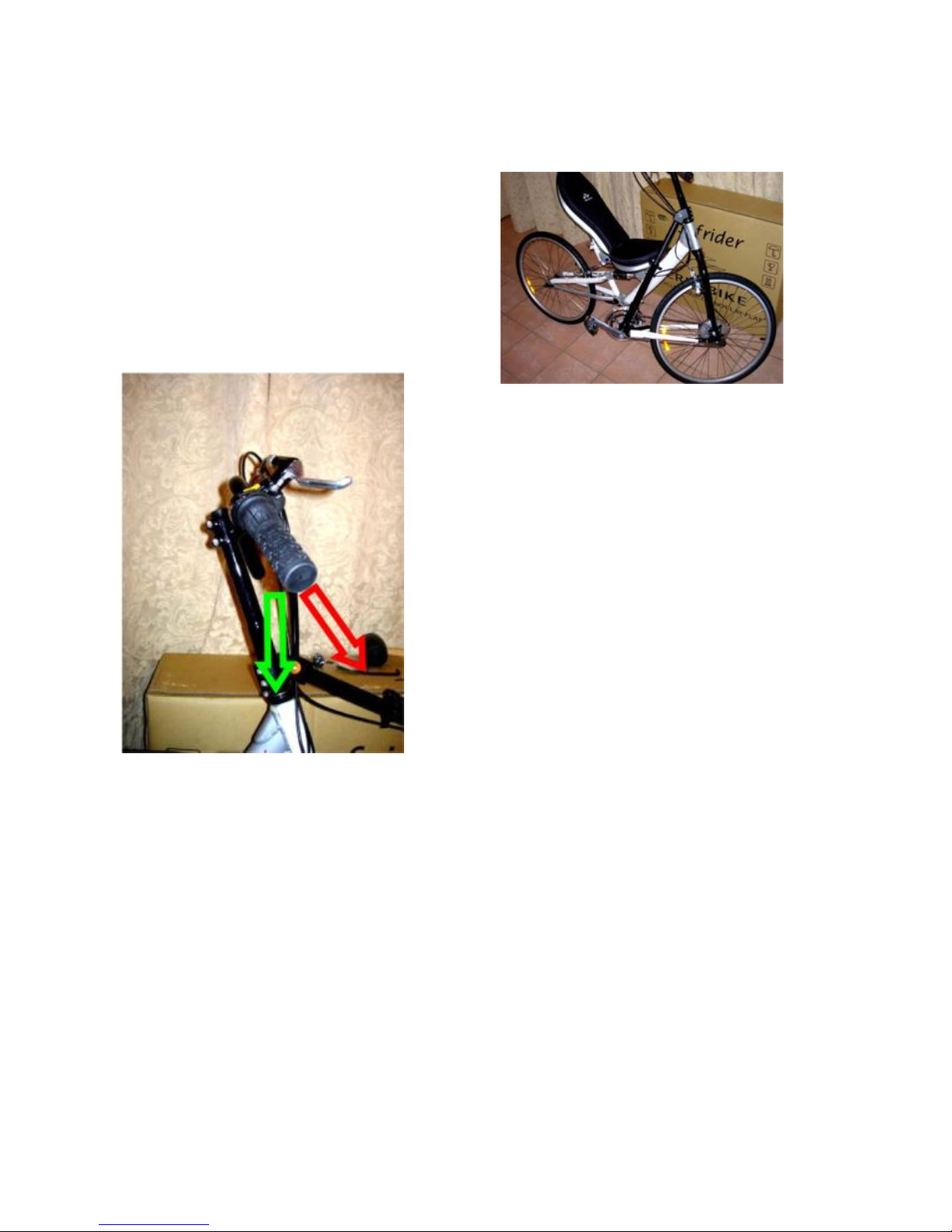
The handlebar grip may come from the factory
rotated so they sweep back (see the red arrow in
fig. 35). This position will cause strain on your
wrists. Loosen the four bolts (5 mm Allen
wrench) that secure the bar to the handlebar
extension, and rotate the grips STRAIGHT
DOWN (like the green arrow).
fig. 35 …you’ll thank us later.
You may also take this opportunity to fine tune
the position of your grip shifters or brake
levers. They should be comfortab le for you.
You may want to ride awhile before you do
this. You can also adjust the handlebar up or
down, but start with the handlebar extension
flush with the top of the steering extension
tube.
This is the proper parking position:
fig. 36
Note that parking the bike in “crank forward”
position is for photo ops only. Turn the wheel
to the right for stable parking with the kickstand
engaged.
Page 11

Cruzbike Sofrider v2 Assembly Instructions - 3/1/2011
Cruzbike Sofrider v2 Assembly page 11 of 11
Step 10:
Time to check the headset bearings. Hold the
front brake on tight and rock the bi k e
backwards and forwards. If there is any click or
movement in the headset, then continue below
to fine-adjust the bearings.
The Diatech ring is an expandi ng ring that
creates the needed pressure on the headset
bearings as you tighten its pinch b o lt.
The procedure for adjusting the headset
pressure is as follows
1) Loosen the two bolts of the Pivot clamp a nd
the pinch bolt on the DiaTech ring c lamp just
above the head tube (5 mm Allen wrench).
2) Tap (with a rubber hammer) the steering
extension tube to make sure it is snugly down
around the steering tube, AND then tap the
pivot clamp down snugly onto the top of the
DiaTech ring. Now secure the pivot clamp
bolts.
3) Now tighten the DiaTech pinch bolt, to a p ply
pressure to the bearing stack until the unwanted
motion in the headset is gone.
This should be done by your local bicycle
mechanic if any of the above is unclear in any
way.
Step 11:
Inflate tires up to the maximum pre ssure as
indicated on the tire.
Remove protective wrapping material.
Make sure all cables are fully seated in their
cable stops, brakes adjusted, and the AFT QR
clamp secured tightly.
Do a complete safety check and have a
professional bicycle mechanic check the
bicycle before riding. Read and review the
Owner’s manual and obey all safety warnings
before attempting to ride. Failure to do so may
result in serious injury or death.
Adjusting the AFT to suit your x-seam: The
QR clamp on the AFT is designed to be able to
rotate around the lip of the outer tube. Position
it where it is comfortable for you to adjust and
does not impede the FD (front derailleur) cable.
If you are not confident in your knowledge of
how to secure the AFT clamp, ask you local
mechanic. Sometimes the AFT seems difficult
to lengthen, especially for tall people. To make
it easier, pull some extra FD cable through the
pivot clamp tunnel so there is some slack
BEFORE trying to adjust it.
If you experience rou gh s hifting or gear chatter,
have your Front and rear derailleur settings
checked. They are properly set at the factory,
but can get knocked out of place during
shipping.
If your knees hit the handlebar (and the
handlebar is already in its highest position), try
moving the seat forward rela tive to the bracket.
If that doesn’t work, try moving it back. If that
doesn’t work, trying moving the s eat m ount
bracket forward (or backward). There is a
combination of positions for the seat and seat
bracket that will work for 95% of the adult
population.
Check headset tension (Step 10) after your first
ride.
If you have any questions, contact us at
or post your questions on
our user forum at
http://www.cruzbike.com/forums
.
 Loading...