

Page 1
MERCEDES BENZ
2015 - 2016 A-class (W176)
2015 - 2016 B-class (W24)
2015 - 2017 C-class (W205)
2015 - 2016 E-class (W212)
2015 - 2016 CLA (C117)
2015 - 2016 CLS (W218)
2015 - 2016 GLA (X156)
2015 - 2016 GLC (X205)
Rear-view camera input with Dynamic Guide Lines
Control by factory infotainment
On-screen display and setup
2 trigger outputs (+12V max. 1A), separately adjustable switching events (CAN, ACC, rear-view camera,
reverse gear)
Front camera input
Front camera input can also be used as an Auxiliary Video Input (Crux part# AUX-MB2, OBD2 Audio Aux
coding, may be required to create an Auxiliary Audio Input) (Sold separately).
Automatic switching to rear-view camera input on engagement of reverse gear from all operation modes
Forced rear-view camera option
Manual return from rear-view and front camera (cancellation of automatic switching)
Compatible with all factory video accessories (e.g. rear-view camera, DVD-changer, etc.)
Plug & Play installation
COMAND Online NTG5/5.1, Audio20 NTG5/5.1 with 4pin HSD LVDS connector on the monitor
1 / 12
Rev.051916
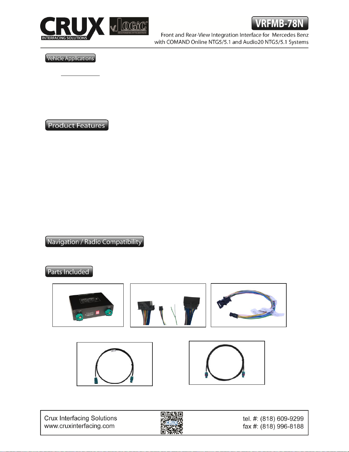
Interface Box
MB-78N Harness
Power/CAN Harness
LVDS1 OUT (Female to Female)
LVDS IN (Male to Female)
Page 2
Setting the DIP switches of the Interface Box.
DIP 1 on the back of the interface box is used to set the monitor type. DIP 2 and 3 must be set to OFF.
Device
DIP 1
COMAND Online NTG5/5.1
ON
7 inch Display
Audio20 NTG5/5.1
OFF
6 inch Display
After each change of the DIP switch settings you have to execute a power reset of the interface box!
2 / 12
Rev.051916
Page 3
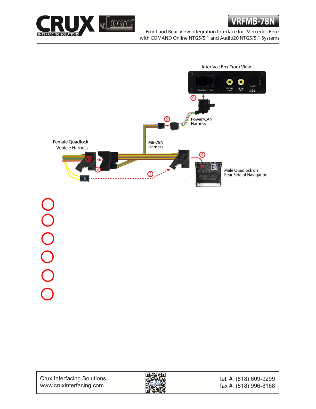
Connecting Interface box and harnesses
Remove the female Quadlock connector of the vehicle harness from the rear of the headunit.
Remove optical leads from the female Quadlock connector of the vehicle harness and insert them into
the female Quadlock connector of MB-78N harness at the same position.
Connect the female Quadlock connector of vehicle harness to the male Quadlock connector of
MB-78N harness.
Connect the female Quadlock connector of MB-78N harness to the male Quadlock connector of the
navigation computer.
Connect the female 8 pin molex connector of the MB-78N harness to the male 8 pin molex connector of
the Power/CAN harness.
Connect the female 12pin AMP connector of the Power/CAN harness to the front side of the VRFMB78N interface box.
1 2 3 4 5
6
3 / 12
Rev.051916
Page 4
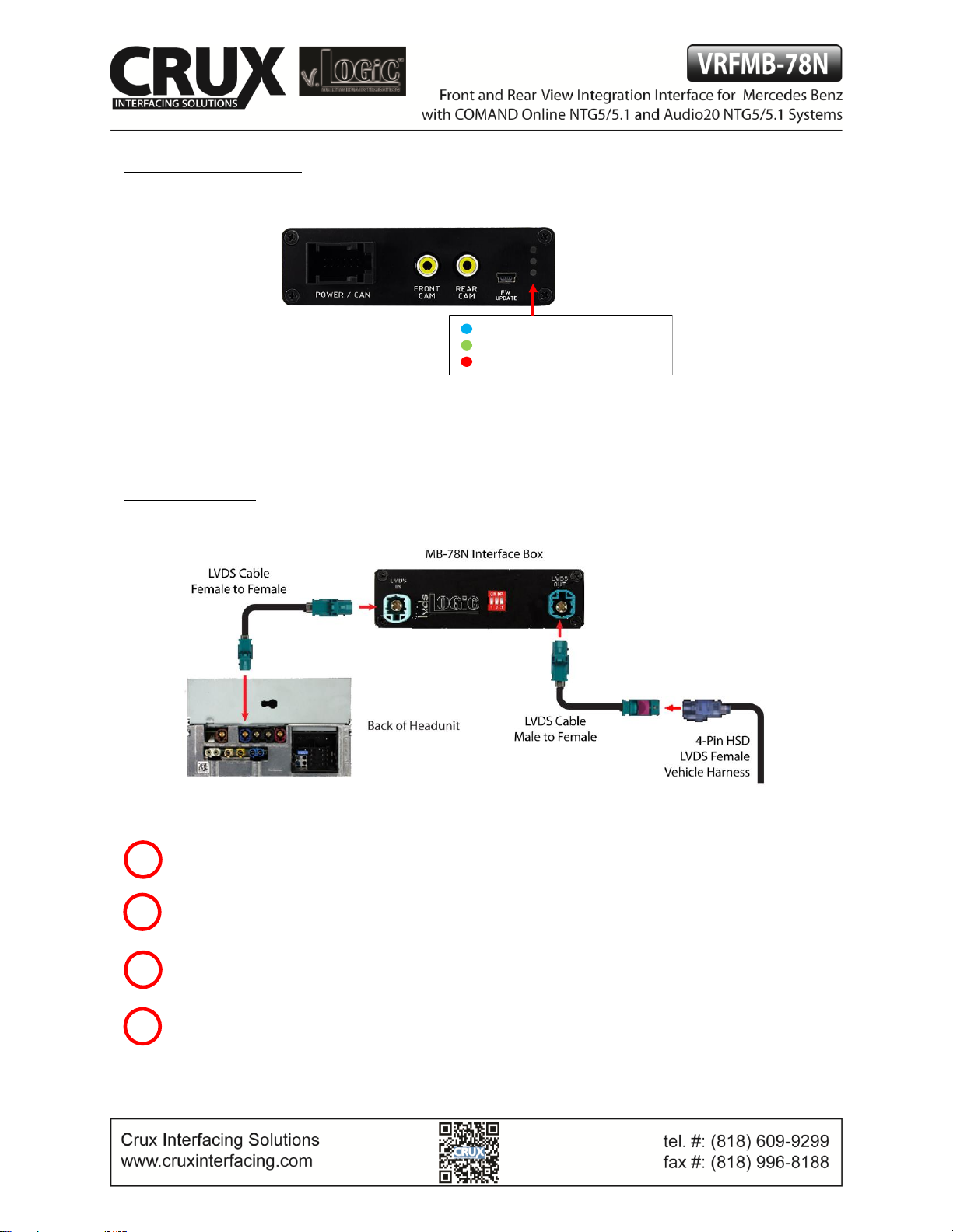
LEDs of the Interface box
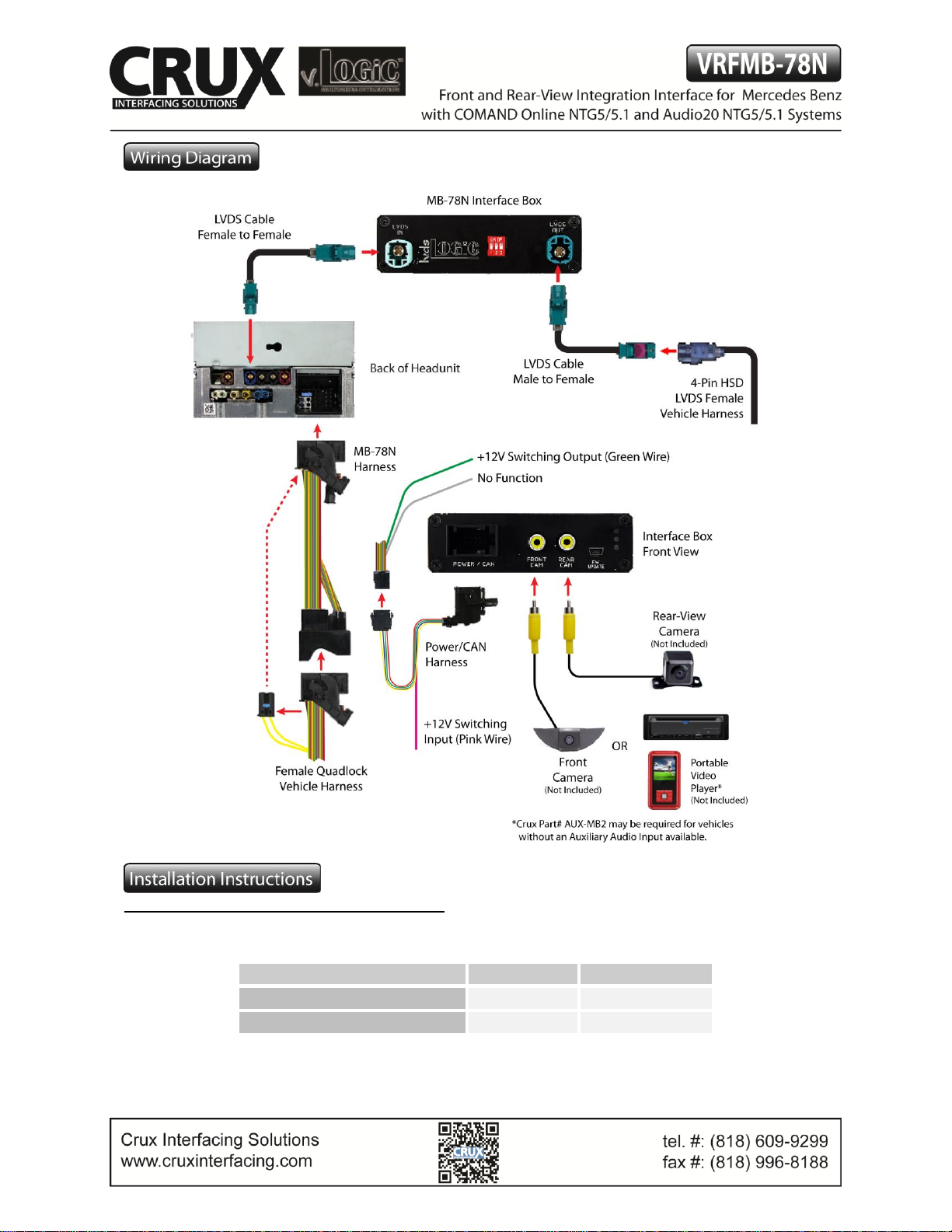
LVDS Connection
Connect the female 4pin HSD LVDS connector of the LVDS cable to the male 4pin HSD LVDS connector
(LVDS-IN) on the rear of the VRFMB-78N interface box.
Remove the Blue female 4pin HSD LVDS connector of the vehicle harness at the back of the head unit
and connect it to the male 4pin HSD LVDS of the LVDS cable.
Connect the female 4pin HSD LVDS connector of the LVDS cable to the male 4pin HSD LVDS connector
(LVDS-OUT) on the rear of the VRFMB-78N interface box.
Connect the female 4pin HSD LVDS connector of the LVDS cable to the Pink male 4pin HSD LVDS
connector on the rear of the head unit.
1 2 3
4
Valid input source
CAN ok
Power
4 / 12
Rev.051916
Page 5

Connection to the aftermarket front camera
Connect the video RCA of the after-market front camera
to the female RCA connector “FRONT CAM” of the
interface box.
The Pink wire of the Power/CAN harness can be used for
+12V electric power supply (max. 1A) of the aftermarket
front camera. Configure in the OSD-menu “MISC”, Menu
item “POWER OUT 1” the designated electric power
supply (see chapter “Configurable switching outputs”).
Settings for connecting an aftermarket front camera
You have to configure some settings in the OSD-menu’s INPUTS and MISC if you want to connect an
aftermarket front camera (Operation of the OSD: see chapter “OSD-Operation”).
1
2
5 / 12
Rev.051916
Page 6

OSD Menu
Menu item
Setting
Description
INPUT
FVC
OFF
No front camera connected
ON
Switches to front camera if parking process is enabled
and reverse gear is released
OPTION
PARK LOGIC
RGearOnly
Enabled while parking process
RGearSpeed
Enabled while parking process and up to 18 mph
RGearTime
Enabled while parking process and up to 20 seconds
Note: You can deactivate the enabled parking process by pressing the “Hands-free Mode OFF” or “Right
Arrow” button on the steering wheel controls. After deactivation you cannot enable the parking process
again until the vehicle is driving faster than 18 mph or the ignition is switched off.
Connection to the aftermarket rear view camera
Connect the video RCA of the after-market rear
view camera to the female RCA connector “REAR
CAM” of the interface box.
The Green wire of harness Power/CAN harness can
be used for +12V power supply (max. 1A) of the
after-market rear view camera. Configure in the
OSD-menu “MISC”, menu item “POWER OUT 2” the
designated power supply (see chapter
“Configurable switching outputs”).
1
2
6 / 12
Rev.051916
Page 7

Settings for connecting an aftermarket rear view camera
You have to configure some settings in the OSD-menus INPUTS and MISC if you want to connect an aftermarket
rear view camera (Operation of the OSD: see chapter “OSD-Operation”).
OSD Menu
Menu item
Setting
Explication
INPUT
RVC
OFF
No rear-view camera connected
ON
Switches to rear view camera if reverse gear is
engaged and/or PDC display is displayed
OEM
If a factory rear view camera is present.
The interface turns off, if reverse gear is enabled
and it displays factory rear view camera
OPTION
PARK LOGIC
RGearOnly
Enabled while parking process
RGearSpeed
Enabled while parking process and up to
18 mph
RGearTime
Enabled while parking process and up to
20 seconds
RVC LINES
OFF
Dynamic guide lines deactivated
ON
Dynamic guide lines activated
Note: You can deactivate the enabled parking process by pressing the “Hands-free mode OFF” or “Right
Arrow” button on the steering wheel. After deactivation you cannot enable the parking process again
until the vehicle is driving faster than 18 mph or the ignition is switched off.
7 / 12
Rev.051916
Page 8

Configurable Trigger Outputs
You can configure both +12V trigger outputs
separately. The Pink wire is POWER OUT 1 and
the Green wire is POWER OUT 2.
Note: You can configure the both trigger outputs in the
OSD-Menu MISC separately (Operation of the OSD: see
chapter “OSD-Operation”).
OSD
Menu
Menu item
Setting
Description
OPTION
POWER OUT1
(Pink)
POWER OUT2
(Green)
CAN
+12V when the interface is on (Red LED on)
ACC
+12V when ignition is on
CAM
+12V when the rear-view camera input is
activated
RGEAR
+12V when reverse gear is engaged
AVS
+12V when interface video-source is active
OFF
Trigger output deactivated
1
Rev.051916
MB-78N
Harness
8 / 12
Rev.051916
Page 9

Dynamic Guide Lines
You have to configure some settings in the OSD menu
OPTION if you want to activate the Dynamic Guidelines
(Operation of the OSD: see chapter “OSD-Operation”).
OSD Menu
Menu item
Setting
Description
OPTION
RVC LINES
OFF
Dynamic Guide Lines deactivated
ON
Dynamic Guide Lines activated
CAR TYPE
A/B/C/CLA/CLS/
E/GLA/GLC
Vehicle type selection
Picture settings
You can change the picture settings in the OSD Menu IMAGE (activation only from interface AV level possible).
◦ Brightness
◦ Contrast
◦ Saturation
◦ Hue
◦ Sharpness
Note: The picture settings will be retained for each AV-source separately.
9 / 12
Rev.051916
Page 10

Operation
OSD – On-Screen Display
You can change the basic configurations of the interface in
the OSD (on screen display).
OSD – Operation
You can control the OSD by steering wheel buttons.
Set the instrument cluster screen to “NAVI” before
you start the OSD control.
Mercedes Steering Wheel Controls version 1
Options
Options
Enter
Longpress=enter OSD
10 / 12
Rev.051916
Page 11

Mercedes Steering Wheel Controls version 2
OSD – Additional setting options
The following settings in the OSD menus OPTION and OSD can be configured over and above the
described settings in this manual (Operation of the OSD: see chapter “OSD-Operation”):
OSD Menu
Menu item
Setting
Description
OSD
POS. X
0-xxx
Horizontal position of the OSD
POS. Y
0-xxx
Vertical position of the OSD
SIZE
SMALL
Small OSD menu windows
LARGE
Large OSD menu windows
OSD TIMEOUT
2-20
Time setting for automatic OSD shutoff
INFO
VERSION
X.XX.XX
Displays the current SW version
OPTION
FACTORY RESET
Resetting to factory settings
Options
Options
Enter
Longpress=enter OSD
11 / 12
Rev.051916
Page 12

Video-In-Motion function
It is possible to activate and deactivate the video-in-motion in the OSD menu “OPTION”
(Operation of the OSD: see chapter “OSD-Operation”).
OSD Menu
Menu item
Setting
Description
OPTION
VIM
ON
Video-in-motion activated
OFF
Video-in-motion deactivated
The Video-In-Motion function is permanently active without disturbing the navigation
performance.
Selecting the interface as current video source
A Long press of the “Hands-free Mode OFF” OR a Long press “Right Arrow” button will choose
the interface as current video source.
A Short press of the “Hang-Up” button will switch the video sources (cameras). Each short press
will switch to the next enabled input. If all inputs are enabled the order is:
FRONT CAM REAR CAM …
Inputs which are not enabled are skipped.
Longpress=enter /leave interface level Shortpress=switch video sources
12 / 12
Rev.051916
 Loading...