

Page 1
BMW
1 SERIES
2007 - 2011 1 Series 3-door hatchback
2007 - 2013 1 Series 2-door coupe (1M)
2004 - 2012 1 Series (5-door)
2008 - Up 1 Series Convertible
3 SERIES
2005 - 2011 3 Series Sedan
2005 - 2011 3 Series Wagon
2006 - 2013 3 Series Coupe
2007 - UP 3 Series Convertible
5 SERIES
2004 - 2010 5 Series Sedan
2004 – 2007 5 Series Wagon
6 SERIES
2004 - 2010 6 Series Coupe
2004 - 2010 6 Series Convertible
X SERIES
2007 - 2013 X5 Sports Activity Vehicle
2008-2011 X6 Sports Activity Coupe
Plug and Play Installation
Media Controller with controls by factory infotainment (iDrive)
Rear-view camera input
Front camera input
Front camera input can also be used as an Auxiliary Video Input
Manual switching to rear-view camera (only for vehicles with PDC button)
Manual return from rear-view and front camera (cancellation of automatic switching)
2 trigger outputs (+12V max. 1A), separately adjustable switching events (CAN, ACC, camera,
reverse gear)
Picture-in-picture mode combining aftermarket rear-view and front camera picture(s) with factory
parking sensor graphics
Compatible with all factory video accessories (e.g. rear-view camera, Top-View Camera System)
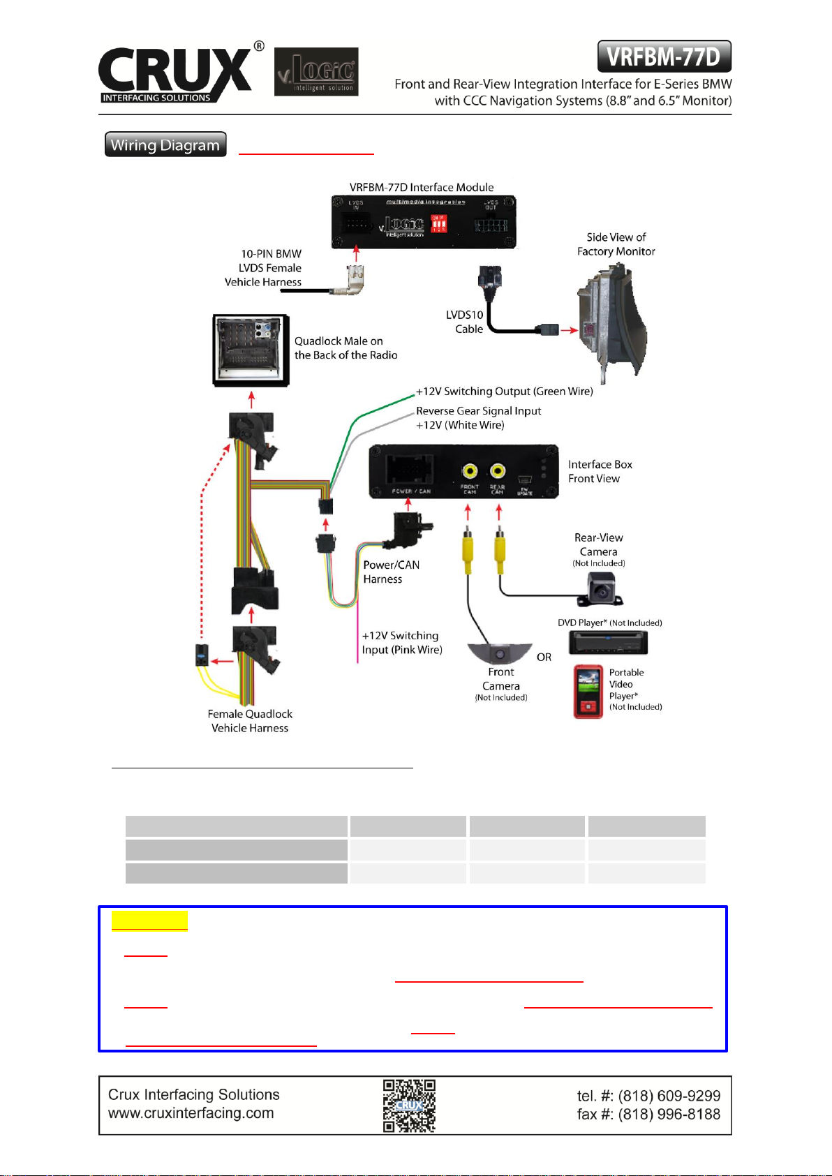
E-series with Navigation System or radio with 6.5“ or 8.8“ monitor and 10-PIN LVDS Connector
1 / 10
Rev.040816
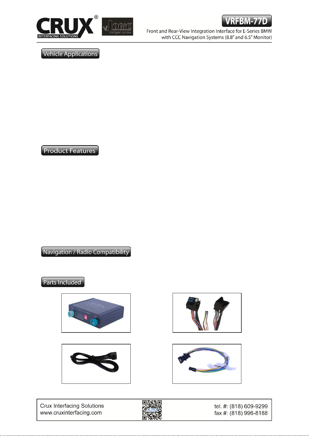
Interface Box
BM-77D Harness
Power/CAN Harness
LVDS10 Cable
Page 2
See Warning below
Setting the DIP Switches of the VRFBM-77D
DIPs 1 and 2 on the back of the interface box are used to set the monitor type. The default setting is:
Vehicle / Navigation
Dip 1
Dip 2
Dip 3
M-ASK
OFF
No function
No function
CCC
ON
No function
No function
After each change of the DIP Switch settings you have to execute a power reset of the interface!
WARNING:
1. DO NOT connect the Quadlock Connector to Factory Radio CD Headunit UNLESS the 10 Pin LVDS Cable has
been properly and completely connected to factory display and all the other 10 Pin LVDS cable connections have
been made according to the wiring diagram above or the factory display will be damaged;
2. DO NOT connect the 10 Pin LVDS Cable when the Radio is Powering ON or the factory display will be damaged;
3. When the Radio CD Headunit is active (powered ON ), DO NOT disconnect any of the 10 pin LVDS Connections
or the factory display will be damaged.
2 / 10
Rev.040816
Page 3
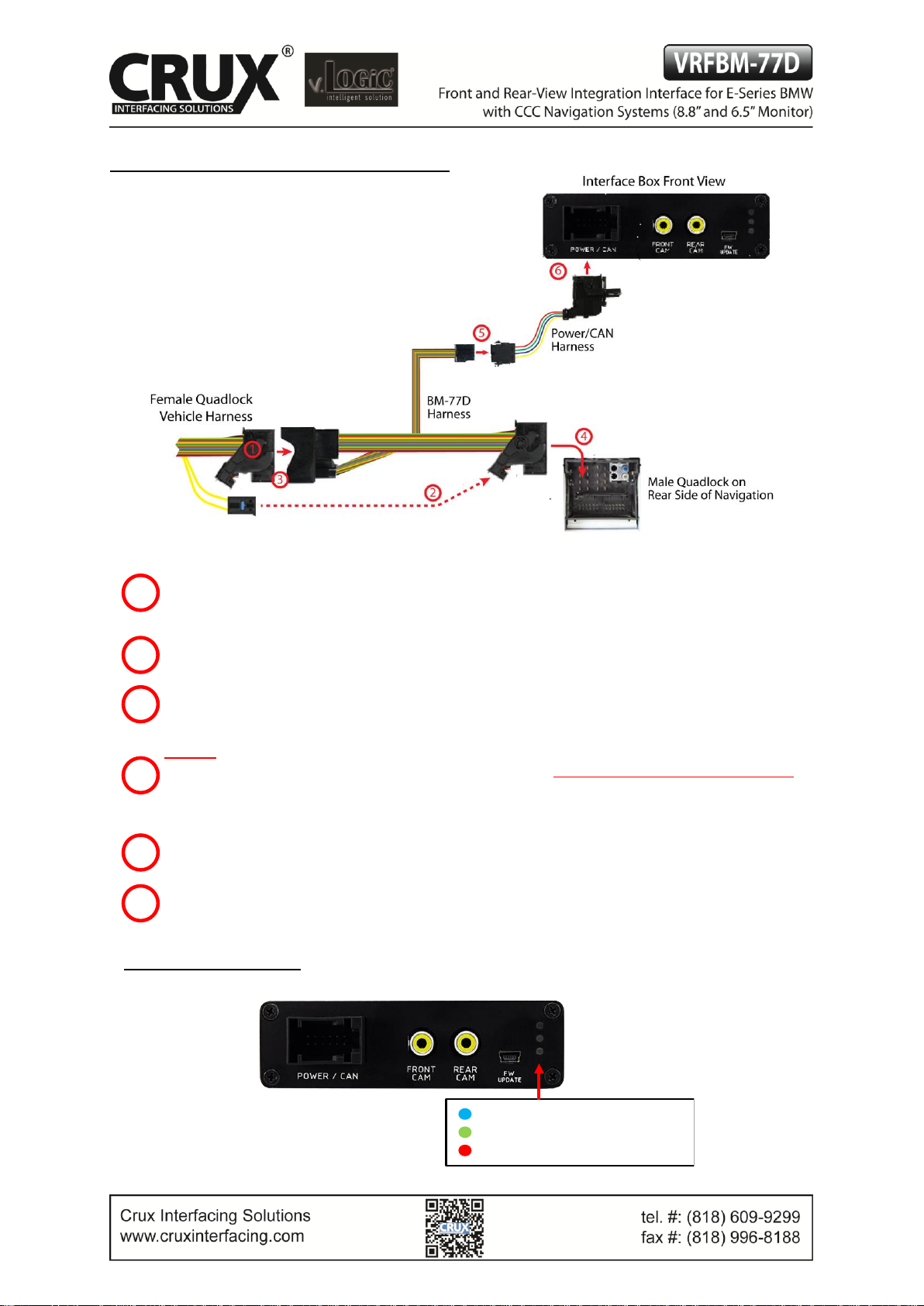
Connecting the Interface Box and Harnesses
Remove the female Quadlock connector of the vehicle harness from the rear of the navigation
computer.
Remove optical leads from the female Quadlock connector of the vehicle harness and insert them into
the female Quadlock connector of BM-77D harness at the same position.
Connect female Quadlock connector of vehicle harness to the male Quadlock connector of BM-77D
harness.
DO NOT connect the female Quadlock connector of BM-77D to the male Quadlock connector of the
navigation radio UNTIL the 10-pin LVDS cables are connected or the factory display will be damaged.
See next page for 10-Pin LVDS connection before plugging in the female Quadlock connector to the
radio.
Connect female 8 pin molex connector of the BM-77D harness to the male 8 pin molex connector of
the Power/CAN harness.
Connect the female 12pin Power/CAN harness to the front side of the VRFBM-77D interface box.
LEDs of the Interface Box
4
1 2 3
5
6
Valid input source
CAN ok
Power
3 / 10
Rev.040816
Page 4

LVDS Connection
Connect the female 10 Pin Micro-Fit connector of the LVDS10 cable the male 10 Pin Micro-Fit
connector (LVDS-OUT) on the rear of the VRFBM-77D interface box.
Remove the female 10 Pin BMW LVDS connector of the vehicle harness at the side of
the factory monitor and connect it to the male 10pin BMW LVDS connector (LVDS-IN)
on the front of the VRFBM-77D interface box.
Connect the female 10 Pin BMW LVDS connector of the LVDS10 cable to the male 10pin BMW
LVDS connector of the factory monitor. You can now connect the female Quadlock connector to
the back of the radio.
Connection to the Aftermarket Front Camera
Connect the video RCA of the aftermarket front camera to
the female RCA connector “FRONT CAM” of the
VRFBM-77D interface box.
The pink wire of the Power/CAN2 harness can be used for
+12V power supply (max. 1A) of the aftermarket front
camera. Configure in the OSD-menu “MISC”, menu item
“POWER OUT 2” the designated power supply (see chapter
“Configurable Switching Outputs”).
1
2 3 2
4 / 10
1
Rev.040816
Page 5

Settings for Connecting an Aftermarket Front Camera
You have to configure some settings in the OSD-menu’s INPUTS
and MISC if you want to connect an aftermarket front camera
(Operation of the OSD: see chapter “OSD-Operation”).
OSD-Menu
Menu Item
Setting
Description
INPUTS
FRONT CAM
OFF
No front camera connected
ON
Switches to front camera if parking process is
enabled and reverse gear is released
Reverse Logic
Intelligent
For vehicles with PDC button. Enabled while
parking process and up to 12 mph or together
with PDC if existing
Gear only
For vehicles without PDC button. Enabled while
parking process and up to 12 mph.
MISC
OEM PDC CAR
Horizontal
PDC-display of the vehicle is horizontal
Vertical
PDC-display of the vehicle is vertical
Note: You can deactivate the enabled parking process by pressing the iDrive or by enabling other modes (e.g.
radio). After deactivation you cannot enable the parking process again until the vehicle is driving faster than
12 mph and the ignition is switched off and on, or the PDC be disabled and enabled again.
Connection to the Aftermarket Rear-View Camera
You have to configure some settings in the OSD-menus INPUTS and MISC if you want to connect an aftermarket rear-view camera (Operation of the OSD: see chapter “OSD-Operation”).
5 / 10
Rev.040816
Page 6

OSD-Menu
Menu Item
Setting
Description
INPUTS
REAR CAM
OFF
No rear-view camera connected
ON
Switches to rear-view camera if reverse gear is engaged
and/or PDC-display is displayed
OEM
If a factory rear-view camera is connected.
Interface turns off, if PDC or reverse gear is enabled
and it displays factory rear-view camera and/or PDCdisplay
Reverse Logic
Intelligent
For vehicles with PDC button. Enabled while parking
process and up to 12 mph or together with PDC if
available
Gear only
For vehicles without PDC button. Enabled while parking
process and up to 12 mph.
MISC
OEM PDC CAR
Horizontal
PDC-display of the vehicle is horizontal
Vertical
PDC-display of the vehicle is vertical
Note: You can deactivate the enabled parking process by pressing the iDrive or by enabling other modes (e.g.
radio). After deactivation you cannot enable the parking process again until the vehicle is diving faster than 12
mph, the ignition is switched off and on or the PDC is disabled and enabled again.
Configurable Trigger Outputs
You can configure the both +12V trigger outputs separately. The Pink wire is POWER OUT 1 and the
Green wire is POWER OUT 2.
6 / 10
Rev.040816
Page 7

Note: You can configure both trigger outputs in the OSD-menu MISC separately (for Operation of the
OSD: see chapter “OSD-Operation”).
OSDMenu
Menu Item
Setting
Description
MISC
POWER OUT1
(Pink Wire)
POWER OUT2
(Green Wire)
CAN
+12V when the interface is on (Red LED on)
Ignition
+12V when ignition is on
Rear Cam
+12V when the rear-view camera input is activated
Reverse Gear
+12V when reverse gear is engaged
OFF
Trigger output deactivated
Picture Settings
Picture Format
You can change the picture format by a long press of the Menu Button (1) on the
BMW iDrive or on the 2-button (2) iDrive in Mini while in the respective video mode.
The following options are available:
8.8” 24:10 Ultra wide monitor:
◦ FULL = 24:10 interface full screen mode
◦ Zoom = 24:10 interface full screen mode zoom
◦ 16:9 = 16:9 interface picture central
◦ 4:3 = 4:3 interface picture central
◦ AV + LVDS = 16:9 interface picture on left side, factory picture on right side
◦ LVDS + AV = 16:9 factory picture on left side, interface picture on right side
6.5” 16:9 monitor:
◦ FULL = 16:9 interface full screen mode
◦ ZOOM = 16:9 interface full screen mode zoom
◦ 4:3 = 4:3 interface picture central
Note: The picture format will be retained for each video source separately.
Picture Settings
You can change the picture settings in the OSD-menu IMAGE (Operation of the OSD: see chapter “OSDOperation”).
◦ Brightness
◦ Contrast
◦ Saturation
◦ Hue
◦ Sharpness
Note: The picture settings will be retained for each AV-source separately.
7 / 10
Rev.040816
Page 8

Operation
OSD – On-Screen Display
You can change the basic configurations of the interface in the OSD (On Screen Display).
OSD – Operation
You can control the OSD by iDrive.
1- and 2-Button iDrive
Note: If the interface is selected as active video source then the OSD menu is activated via iDrive button "OK"
(press and hold) + "iDrive-right". In this OSD menu only image adjustments can be made.
Back + leaving OSD
Long: enter OSD
Short: OK
OK
Options
Options
Options
8 / 10
Rev.040816
Page 9

2-Button iDrive in Mini
OSD – Additional Setting Options
The following settings in the OSD-menus OSD and MISC can be configured over and above the described
settings in this manual (Operation of the OSD: see chapter “OSD-Operation”):
OSD-Menu
Menu Item
Setting
Description
H POSITION
0-xxx
Horizontal position of the OSD
V POSITION
0-xxx
Vertical position of the OSD
MISC
VERSION
X.XX.XX
Displays the current SW-version
FACTORY RESET
Reset to Factory Settings
Optio
OK
Options
Long press = enter/ leave OSD
Short press = leave OSD + back to the
main
9 / 10
Rev.040816
Page 10

Video-In-Motion Function
It is possible to activate and deactivate the video-in-motion in the OSD menu “MISC” (Operation of the OSD:
see chapter “OSD-Operation”).
OSD-Menu
Menu Item
Setting
Description
MISC
VIM
ON
Video-In-Motion activated
OFF
Video-In-Motion deactivated
NOTE: The Video-In-Motion function is permanently active without disturbing the navigation performance.
Selecting the Interface as Current AV Source
BMW 2-Button iDrive Mini 2-Button iDrive
A Long press of the Menu-button will select the interface as current video source.
A Short press of the CD Button or the MENU Button will switch the video sources (cameras or other video
source). Each short press will switch to the next enabled input. If all inputs are enabled the order is:
FRONT CAM REAR CAM …
Inputs which are not enabled are skipped.
CCC Navigation Screen
10 / 10
Rev.040816
 Loading...