

Page 1
MATCH LOOSE WIRES TO AFTERMARKET RADIO
RADIO REPLACEMENT W/SWC RETENTION FOR FORD, LINCOLN, MERCURY VEHICLES 2005-2012
Rev. 050915
SWRFD-60
FORD
2007 - 2010 Edge
2008 - 2012 Escape
2007 - 2012 Expedition
2006 - 2010 Explorer
2007 - 2010 Explorer Sport Trac
2009 - 2012 F-150
2008 - 2012 F-250
2008 - 2012 F-350
2008 - 2012 F-450
2005 - 2007 Five Hundred
2008 - 2011 Focus
2006 - 2007 Freestyle
2006 - 2012 Fusion
2005 - 2012 Mustang
2008 - 2012 Taurus
LINCOLN
2009 - 2011 MKS
2007 - 2010 MKX
2007 - 2010 MKZ
2007 - 2012 Navigator
2006 - 2006 Zephyr
MERCURY
2007 - 2010 Mariner
2006 - 2010 Milan
2005 - 2010 Montego
2006 - 2010 Mountaineer
2008 - 2009 Sable
work. Following these instructions from “Start” to” Finish” will ensure
9:00 AM – 5:00 PM PDT at 1 (855) 822-1348. We are here to help.
PARTS INCLUDED:
(1) FD-60 Analog SWC Interface Module
(1) FD-60 Digital SWC Interface Module
(1) FD-60 24-Pin Harness
(1) FD-60 Sub Harness
(1) Instruction Sheet
PRECAUTIONS:
- Remove the negative side of the battery to avoid any short circuits
during the installation.
- Do not install the interface near any major components or near the
HVAC system. This may cause damage or overheating to the vehicle.
PRELIMINARY:
Please read the entire manual before installing this interface.
Before installing this interface please review the options before
removing the factory radio. Some options may need to be adjusted
prior to removing the factory radio.
WIRING COLOR CODES
Black = Ground
Red = Accessory (2A Max)
Yellow = Constant
Orange = Illumination (100mA Max)
Blue/White = Antenna Turn-On
White = Left Front (+)
White/Black = Left Front (-)
Gray = Right Front (+)
Gray/Black = Right Front (-)
Green = Left Rear (+)
Green/Black = Left Rear (-)
Purple = Right Rear (+)
Purple/Black = Right Rear (-)
Red/Black = VSS
Red/White = Reverse
Blue/Yellow = SWC for Kenwood
SWC 4-PIN CONNECTORS
The module allows for both type of SWC connections:
Option A is used for the Alpine, Clarion, JVC, and Kenwood units.
(Blue/Yellow wire attached)
Option B is used for the Pioneer, and Sony units. (See Overview)
Select the proper harness type for your aftermarket radio and
connect the 4-pin molex to its proper connection.
DETERMINE IF THE VEHICLE IS ANALOG
For the vehicles that have a BROWN and WHITE connection on the
factory connector side, the SWC signal must come from the analog
swc module.
Set dip switches
accordingly.
BROWNWHITE
Wire View
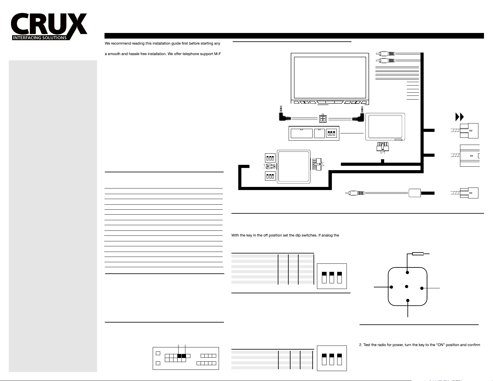
OVERVIEW OF INSTALLATION
AFTERMARKET
RADIO
OPTION A
12-PIN 4-PIN
ON
RADIO
TYPE
(LH SIDE)
1 2 3
4-PIN
SWC
TYPE
(RH SIDE )
SETTING THE RADIO TYPE
This step is done on the module and only needed if the vehicle has
steering wheel controls and you are installing one of the listed radios.
switches are set on the analog module.
RADIO TYPE:
Pioneer/ Sony/ Jensen OFF ON ON
Alpine OFF OFF OFF
Clarion ON ON OFF
Kenwood ON ON ON
JVC ON OFF ON
Blaupunkt ON OFF OFF
ANALOG
SWC
ACE
INTERF
ON
1 2 3
DIP: 1 2 3
4-PIN
GRAY
(female plug )
ON
1 2 3
OPTION B
ON
1 2 3
12-PIN
ANALOG SWC CONNECTION
If your vehicle is analog you will need to set both dip switches on the
Analog module. Both the stereo type and the connection types need to
be set on this module.
Type 1: Vehicles with 4-Button: Vol +/ Vol -/ Memory/ Media
Type 2: Vehicles with 4-Button: Vol +/ Vol -/ Next/ Media
Type 3: Vehicles with 5-Button: Vol +/ Vol -/ Seek +/ Seek -/ Media
Type 4: Vehicles with 6-Button: Vol +/ Vol -/ Seek +/ Seek -/ Media/ Mute
RADIO TYPE:
Ford Type 1 OFF OFF OFF
Ford Type 2 OFF OFF OFF
Ford Type 3 OFF OFF ON
Ford Type 4 OFF OFF ON
DIP: 1 2 3
ON
1 2 3
CAN-RADIO
TYPE
CONNECT THE WIRES,
COLOR FOR COLOR.
auxiliary Input (3.5mm Input)
front left speakers
front right speakers
rear left speakers
rear right speakers
constant
accessory
ground
power antenna
illumination
vss
TO FACTORY
HARNESS
CAN-BUS
BLACK
(female plug)
INTERFACE
12-PIN
16-PIN
(male plug)
24-PIN
(male plug)
ALL GRAY
SUB INPUT
(male plug)
8-PIN
(male plug)
USING A RELAY
The module has been rated for up to 2A max of output.
For applications demanding a continuous output of 3A or more,
we recommend using a standard BOSCH (SPDT) relay.
See your local car audio specialist.
Below is a diagram on how to install the BOSCH relay.
FUSE
CAR 12V CONSTANT
87
CHASSIS
GROUND
86
87a
85
30
NEW ACC 12C (HIGH CURRENT
TO ACC 12V
INSTALLATION TIPS
1. Choose the correct interface for your vehicle (Analog or Digital)
that the new radio is getting power. If no power, please revise your
wiring connections with multi-meter, available at your local dealer
 Loading...