

Page 1
ONSTAR RADIO REPLACEMENT FOR SELECT GM LAN 11-BIT VEHICLES 2004-2011
(FOR VEHICLES WITH OR WITHOUT ON-STAR)
SOOGM-16B
APPLICATIONS
16 AND 14-PIN CONNECTORS
CHEVROLET
2007 - 2010 Cobalt
2007 - 2010 HHR
2008 - 2011 Malibu
PONTIAC
2007 - 2010 G5
2007 - 2010 Solstice
SATURN
2007 - 2010 Aura
2007 - 2007 Ion
2007 - 2009 Sky
24-PIN CONNECTOR
CHEVROLET
2005 - 2006 Cobalt
2004 - 2007 Malibu
PONTIAC
2005 - 2009 G6
We recommend reading this installation guide rst before
starting any work. Following these instructions from “Start”
to” Finish” will ensure a smooth and hassle free installation.
We oer telephone support M-F 9:00 AM – 5:00PM PDT
at 1 (855) 822-1348. We are here to help.
GETTING STARTED
Before removing the factory radio check to see if there any
CD’s in the unit and remove them. Now turn on the radio
and listen to check that the speaker fader control is equally
balanced from front to rear, also check the radio display for
the center fader position setting. The Reason for this is that
the digital ampliers remember the last fader control position before the factory radio was removed. Once you have
installed the new head unit you will no longer have fader
control. Once you have completed these steps you now
may remove the factory radio. Also if the vehicle is equipped
with a rear seat audio system this feature will no longer work
with the new head unit. We always recommend disconnecting the negative terminal on the battery for safety also use
towels or a protective blanket around center console to avoid
scratching dash panels.
TEST FOR HIGH/LOW SYSTEMS:
You will need to perform this simple test rst, to determine
if the audio system is either a “High” or “Low” level output
system. Take the SOOGM-16B module and plug in the
connector harness. Tape o the end of the wires on the harness to avoid any shorting as this could damage the control
module. Now plug in the SOOGM-16B module to the factory
radio harness. On the SOOGM-16B control module set the
rotary switch to “0”. If you disconnected the battery, reconnect it. Turn the ignition key to “on” or “Accessory” position.
Find the OnStar button which will be located either on the
swc, or rear view mirror or steering wheel. Push the OnStar
“Phone” Icon button and listen for the OnStar “Greeting”, if
you hear the greeting move the rotary switch to “9” for High
level input. Now press the OnStar “Phone” icon again to exit
OnStar mode. Now turn o the ignition key and again disconnect the vehicle’s battery. You will NOT need to perform
the “Setting audio level control” as the module has now been
set to the correct audio input level. If however you hear
nothing at all the system is “Low” level and a speaker level
converter will be needed and you will need to perform the
“Setting audio level control” in this guide.
CONNECTING THE WIRE HARNESS:
First check that you have the correct SOOGM-16B harness,
each harness is clearly labeled with all information for its
application and wire location. With the help of the wiring diagram join together the SOOGM-16B harness to the new radio
harness you are installing. Start by making all primary power
connections:
Yellow (+12v Battery): Constant +12 Volts to the new head
unit.
Red (+12V Acc): Switched Accessory from the key. This output supports up to 1 amp continuous. If you need to use this
output for additional accessories, you will need to use a relay
to prevent damage to the SOOGM-16B. See Relay Wiring
Diagram for details.
Black (Ground): To ground wire to new head unit.
Orange/White (Panel Lamp): works in conjunction with the instrument panel dimmer switch, this gives full dimmer control
for the new head unit.
Orange (Illumination): Provides illumination with the head
lamp control switch however doses not dim.
Blue/White (Amp On): Used for amplier turn on.
Blue (Antenna Trigger): Used for power antennas or antenna
amplier turn on.
Yellow/Black (Park): connect to park break on new head unit
Red/White (Rev.): Connect to reverse wire on new head unit
Red/Black (VSS): Connect to Vehicle speed sense wire on
new head unit.
Lt Blue/Yellow (KW Switch): Use on Kenwood remote radio
control (This wire is also used on new JVC units)
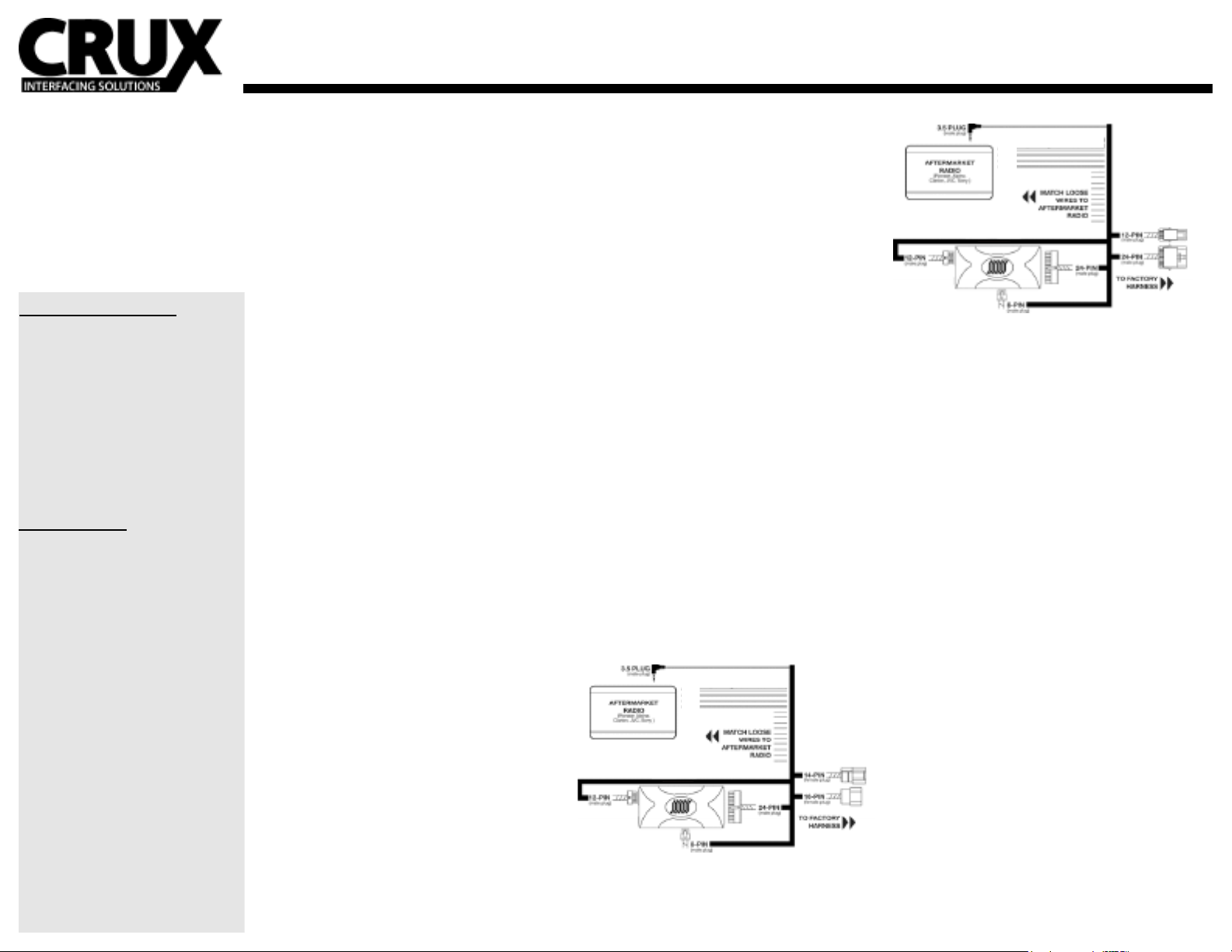
OVERVIEW FOR 14 AND 16-PIN CONNECTOR
OVERVIEW FOR 24-PIN CONNECTOR
FRONT audio inputs:
Gray for right side / White for Left side
REAR audio inputs:
Purple for right side / Green for left side
Wires with a “Black” trace go to Negative (-) side of speaker
and solid colors goes to Positive (+) side of speaker output
from head unit.
USING THE 3.5 STEERING WHEEL CONTROL CABLE
This cable is used on all radios using a 3.5mm remote control
input. Plug this cable in to the port on the back of the radio
labeled for remote. This cable supports Pioneer, Alpine,
Clarion, JVC and Sony radios only no other manufacture is
supported and cable should not be used. This cable is not
needed in vehicles without steering wheel controls.
SETTING THE CONTROLS PRELIMINARY
Once you have made all connections between the SOOGM16B harness and radio harness you are ready to plug in all
the connectors. It is adviseable to put down some towels
around the console area to prevent scratching during this
nal setup. Start by plugging in the SOOGM-16B harness
in to the control module there are 3 connectors and each
will only t its given location. Make sure each connector is
rmly pushed in without forcing, as this can damage the pins
on the connector. Now connect the 2 GM connectors on
the SOOGM-16B harness to the factory radio harness that
you unplugged when you removed the factory radio. Again
these plugs will only t one way, be careful not to force the
connectors. Now set radio down on console and reconnect
the battery on the vehicle not forgetting to tighten down the
terminal.
USING THE SWC WIRE ON NEW JVC UNITS
New JVC units no longer carry the 3.5mm cable and have
added the SWC signal via a Lt. Blue/Yellow wire.
This wire needs to be connected to the SWC wire labeled
“Kenwood” also Lt. Blue/Yellow. Be sure to keep the dial
switch set to number 4 when using JVC units.
(See page 2)
Page 2
ONSTAR RADIO REPLACEMENT FOR SELECT GM LAN 11-BIT VEHICLES 2004-2011
(FOR VEHICLES WITH OR WITHOUT ON-STAR)
SOOGM-16B
APPLICATIONS
16 AND 14-PIN CONNECTORS
CHEVROLET
2007 - 2010 Cobalt
2007 - 2010 HHR
2008 - 2011 Malibu
PONTIAC
2007 - 2010 G5
2007 - 2010 Solstice
SATURN
2007 - 2010 Aura
2007 - 2009 Sky
24-PIN CONNECTOR
CHEVROLET
2005 - 2006 Cobalt
2004 - 2007 Malibu
PONTIAC
2005 - 2009 G6
SETTING AUDIO CONTROL:
At this point you should know what audio output level you
have from the “Test for High / Low level audio systems”. If
your test indicated that you had a “high” Level output and
you were able to hear the OnStar “Greeting” there is no need
to make any changes. Also if the vehicle has steering wheel
controls you may skip down to “Radio Remote Select”, if
not go to OnStar Volume Adjust for vehicles without steering wheel control. However if the test indicated a low level
output you will need to adjust the SOOGM-16B module.
Start by Locate the rotary switch on theSOOGM-16B and set
it to “9”. You must have made all the connection from the
SOOGM-16B to the radio harness. Now plug in your completed assembly to the vehicle factory radio plugs. Turn the
ignition key to the “on” or “accessory” position. You should
now see the radio turn on. Now locate the OnStar button,
this can be found on the swc, or rear view mirror or steering
wheel. Press the OnStar “Phone” icon button to enter OnStar
mode; you should now hear the OnStar “Greeting”, move the
rotary switch to “0”. Now your level is set. If the vehicle has
steering wheel controls you may skip down to “Radio Remote Select”. However if the vehicle has no steering wheel
controls you will need to adjust the volume on the OnStar, go
directly to the next step “OnStar Volume Adjust for vehicles
without steering wheel control”. If no further adjustment is
needed turn ignition key to “O” and go to “Radio Remote
Select”.
Use a small jeweler’s type screw
Driver to make adjustments.
ONSTAR VOLUME CONTROL ADJUSTMENT:
This step is only needed if there are no steering wheel controls and the volume level is either too high or too low. You
may skip this step if the OnStar volume is acceptable. Turn
the ignition key to the “on” or “accessory” position. Start
by pressing the Onstar button and listen to the “Greeting”,
now say “HELP” and listen to the help menu audio as you
adjust the volume. While the “HELP” menu is playing turn
the rotary dial clockwise to increase or counter clockwise
to decrease volume. You will a Soft “Clicking” sound as you
turn the rotary dial through the speakers. Move the dial in 1
second increments until desired volume is achieved. Watch
closely as you turn, DO NOT STOP at the “0” or “ 9” position
this will change your High/Low setting, you may go past
these numbers when adjusting but do not land on them for
more than 2 seconds or your settings will change. Once you
are satised with the volume level press the Onstar “PHONE”
icon to exit OnStar mode. Your level is now set. Turn ignition
key to “O” and go to “Radio Remote Select”. Please ensure
the volume is set at a level that is comfortable for the end
user as there will be no other adjustment once the installation is complete.
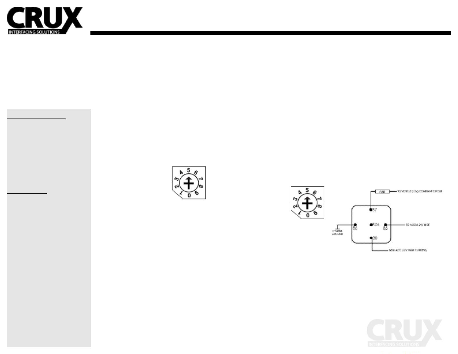
RADIO REMOTE SELECT:
This step is only needed if the vehicle has steering wheel
controls and you are installing one of the listed radios. With
the ignition key in the o position turn the rotary dial on the
SOOGM-16B to the number corresponding to the radio you
are installing. Turn the ignition key to the “on” or “accessory”
position. Now check all steering wheel control functions.
Use a small jeweler’s type screw
Driver to make adjustments.
0. Pioneer
1. Alpine
2. Clarion
3. Kenwood
4. JVC
5. Sony
CHECKING THE INSTALLATION
Now turn on the ignition Key to “on” or “Accessory” and
turn on the radio. Check that all speakers are working and
that balance and fader control are in sink. On vehicles with
digital ampliers there will be NO fader control from the
radio. Check to make sure you have equal front to rear audio
balance, if not you will need to go back to “Getting Started”
to correct the problem. Now check steering wheel controls,
they will function as they did with the factory radio. Also
make sure the OnStar is set at a comfortable audio level.
Remember vehicles without steering wheel controls will not
have any adjustment to the OnStar volume once the radio in
installed.
FINISHING THE INSTALLATION:
Once you have completed your nal check you may now
install the radio into the dash. Make sure to nd a suitable location behind the dash for the SOOGM-16B module keeping
in mind any moving part that could be impeded the operation
of the vehicle. The SOOGM-16B should be mounted so as
not to block the slits in the top of the module. These slits are
for the warning chime speaker and blocking them may cause
the warning chime not to be heard. Take care in tuck all wires
into the dash being careful not to allow pinching or rubbing
of wires once radio is installed. Use tape and wire ties make
a neat wire loom.
RELAY WIRING DIAGRAM
(Relay not included)
For applications demanding more than 1 amps continuous
we recommend the use of a standard BOSCH type SPDT or
STST relay available at your local auto parts supplier.
 Loading...