

Page 1
- Interface includes Audio / Video Input to connect an extra A/V source.
- OEM style Spare Tire mount reverse camera included.
- Camera has moving parking guide lines to show path direction while backing up.
- Activates MYGIG Screen for enabling Video features.
- Supports vehicles with manual transmission. See note below.
- Plug and Play connections for ease of use.
NOTE: Does not supply +12V Reverse Trigger on vehicles with manual transmission.
Camera power must be tapped from the +12V reverse light wire instead.
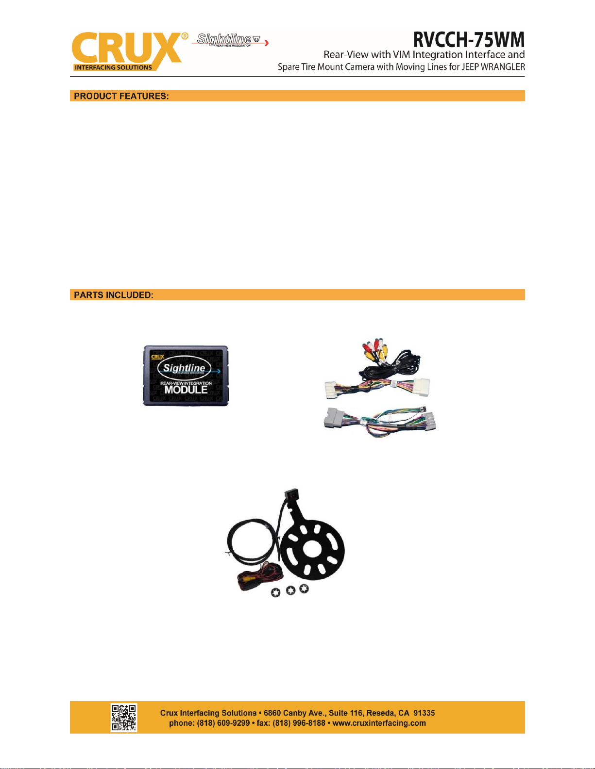
CH-75WM MODULE
CH-75WM HARNESS
CCH-01M SPARE TIRE MOUNT CAMERA with MOVING LINES
Rev.092617
1 / 3
Page 2
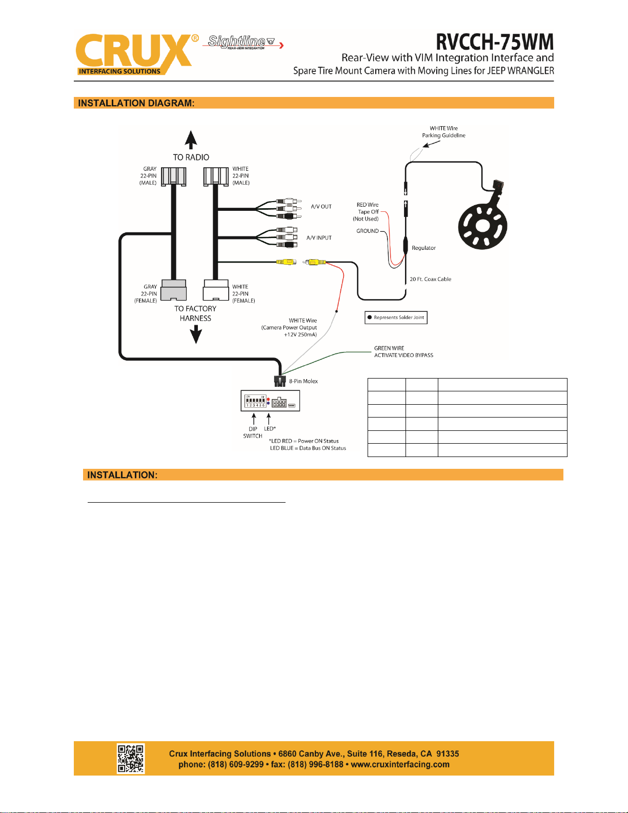
INSTALLING THE CAMERA AND INTERFACE
1. Remove the outside mounted spare tire.
2. Mount the camera’s metal bracket onto the spare tire bolts and secure with the star washers.
3. Route the cable towards the radio and make the power and video connections.
4. Remove the factory radio to gain access to the factory connectors.
5. Plug in the T-harness with WHITE and GRAY connectors. (See Wiring Diagram above)
6. Connect the 8-pin Molex connector from the T-harness with GRAY connectors to the CAN Interface.
7. Use the WHITE 12V Reverse Output wire to power the camera (see Wiring Diagram above). DO NOT
connect the red power wire, near the camera, to the reverse light and insulate this red wire to avoid
from shorting. If the vehicle has a manual transmission, the camera power must be tapped to the
+12V reverse light wire instead. In this case the WHITE 12V Reverse Output wire is not used and
should be insulated to avoid from shorting.
8. Plug in the YELLOW MALE RCA from the camera cable to the YELLOW FEMALE RCA of the T-Harness
with WHITE connectors.
9. Connect GREEN wire to +12V for a non permanent Video in Motion feature.
10. Set the proper DIP Switch settings on the CAN Interface. (See Chart above)
11. Cut the thin white wire on the camera cable to enable the parking guide lines.
12. Test the camera before re-installing the radio.
Rev.092617
2 / 3
Please note that the WHITE 12V
Reverse Output wire does not
supply power on vehicles with
manual transmission and should
be insulated to avoid from
shorting. Connect the camera
power to the OE reverse light
+12V wire instead.
DIP SWITCH SETTING
DIP 1
OFF
VIM Disable
DIP 2
ON
Rear-View Camera Enable
DIP 3
OFF
N/A
DIP 4
OFF
Option for GREEN Wire
DIP 5
OFF
CAN Termination Radio Side
DIP 6
ON
CAN Termination Car Side
Page 3
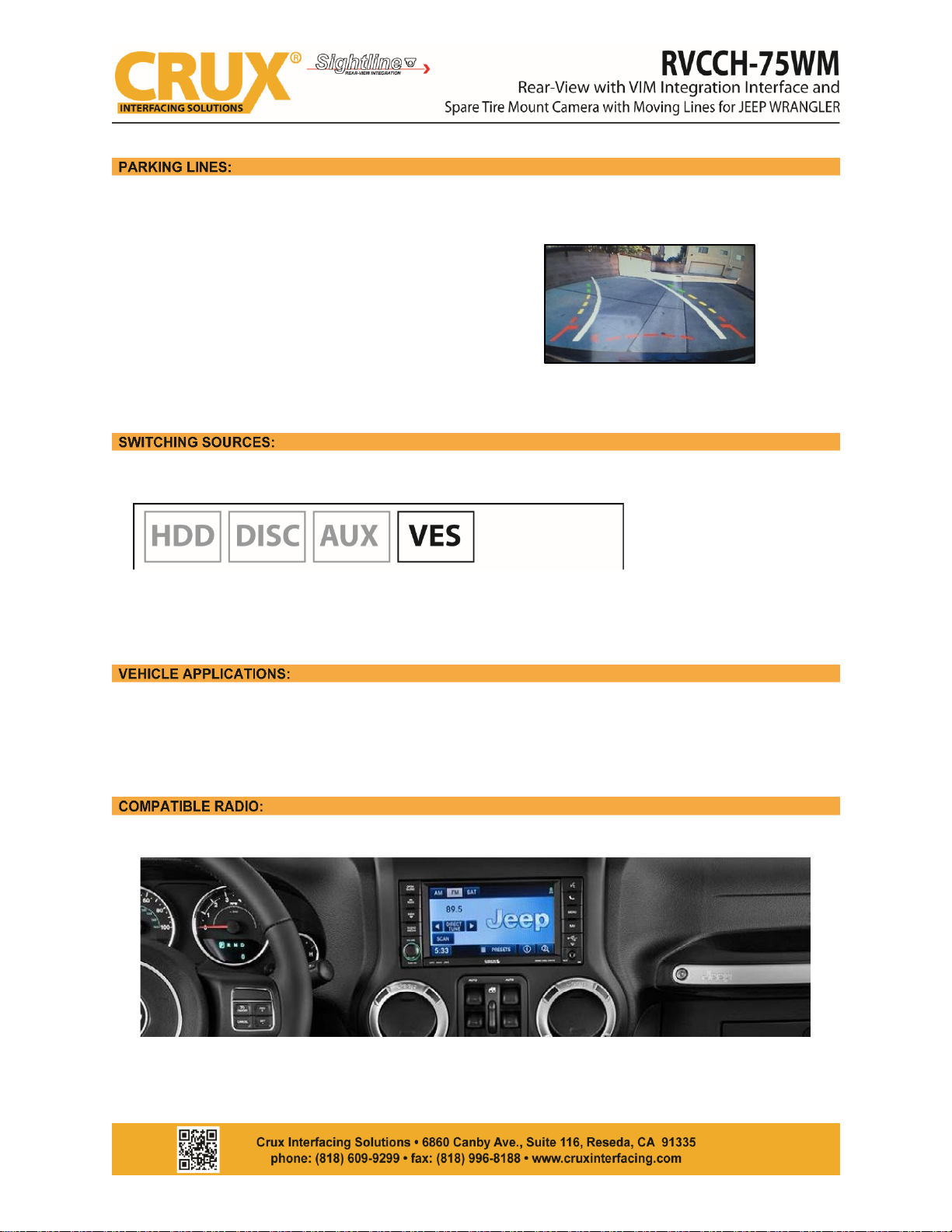
The parking lines are there to assist you while reversing. To activate the parking lines simply cut/disconnect the
WHITE loop wire located near the 4 pin camera connector.
What the Lines mean:
Green Line: CLEAR
Yellow Line: GETTING CLOSE
Red Line: WARNING - VERY CLOSE
White Line: SHOWS THE PATH DIRECTION
VES will be your source for the AV Input.
To access the VES button, press the RADIO/MEDIA button on the left side of the radio. The VES button is only
active after the interface is properly installed.
JEEP
2007 – 2017 WRANGLER
MyGig Radio
Rev.092617
3 / 3
 Loading...