

Crux RVCCH-75B User Manual

INTERFACING SOL UTIONS
DODGE
2014 - 2015 Durango
2014 - 2015 Ram*
JEEP
2014 - 2015 Grand Cherokee
*NOTE: Not compatible with diesel powered RAM trucks
REAR-VIEW & FRONT-VIEW CAMERA
INTEGRATION INTERFACE FOR
DODGE & JEEP VEHICLES 2014-UP
RVCCH-75B
APPLICATION NOTES:
FOR UCONNECT 5” AND 8.4”
DISPLAYS
This interface does not oer the
Force RVC feature.
PARTS INCLUDED
(1) CH-75B RVC Interface Module
(1) CH-75B FVC Interface Module
(1) CH-75B 52-Pin T-Harness (2663)
(1) Instruction Sheet
TECH SERVICES
All our products are manufactured under strict quality control. Each device is being tested before shipment. If nevertheless do occur problems or if
you have technical questions, contact us directly:
Crux Interfacing Solutions Tech Support
1 (855) 822-1348 (Mon - Fri - 9:00 AM - 5:00 PM) Pacic Time
SAFETY PRECAUTIONS
1. Please read through the entire instruction manual before starting any of the installation procedures.
2. We recommend disconnecting the negative side of the battery until ready to code the vehicle.
3. Do not install any of the main modules near any major components or near the HVAC system,
as placing items near the HVAC may cause damage or overheating to the interface.
4. We recommend not disconnecting any of the air bag connections behind the dash panels.
5. This product is under Crux’s 1 year manufacturer’s warranty. Warranty may be voided in the case where
the device shows proof of being opened or improper extreme force.
www.cruxinterfacing.comRev. 051016 1
INTERFACING SOLUT IONS
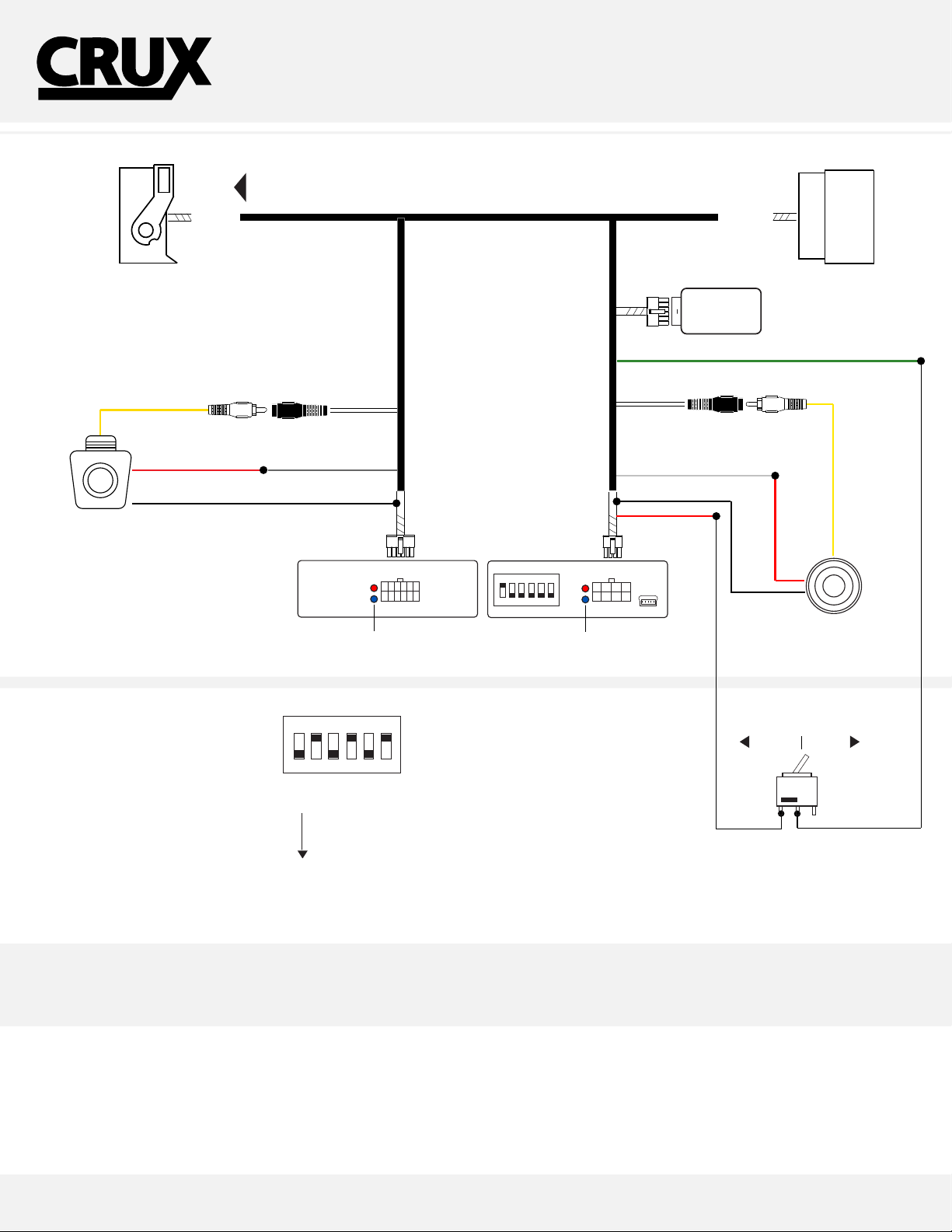
INSTALLATION OVERVIEW
VIDEO
(male plug)
52-PIN
(male plug)
REAR-VIEW & FRONT-VIEW CAMERA
TO FACTORY
RADIO
REAR CAMERA
INPUT
(female plug)
INTEGRATION INTERFACE FOR
DODGE & JEEP VEHICLES 2014-UP
RVCCH-75B
52-PIN
(female plug)
12-PIN
(male plug)
SWITCHER
GREEN/ VIDEO IN-MOTION ACTIVATE
FRONT CAM INPUT
(female plug)
VIDEO
(male plug)
RED/ POWER 12
BLACK/ GROUND - TAP BLACK WIRE ON 8-PIN
REAR CAMERA
(NOT INCLUDED)
DIP SWITCHES OVERVIEW
Make sure to set dip switch number 2
is turned to ON.
Dip 2 = RVC Enable
ACTIVATE
REAR-VIEW
& FRONT VIEW
NOTE: GREEN WIRE AND DIP 1 HAVE
THE SAME FUNCTIONALITY. IF ONE IS
BEING USED THERES NO USE FOR THE
OTHER
GRAY/ REVERSE 12V
12-PIN
(male plug)
8-PIN
MODULE
ON
1 2 3
DIP 1 = OFF
2 = ON
3 = OFF
4 = ON
5 = OFF
DIP 6 = ON
4 5 6
STATUS LED’S
ON
1 2 3
4 5 6
8-PIN
(male plug)
STATUS LED’S
WHITE / 12 OUTPUT (FRONT)
BLACK/
GROUND
RED/
POWER
12V
FRONT CAMERA
(not included)
ENABLEDISABLE
OPTIONAL /
TOGGLE SWITCH
www.cruxinterfacing.comRev. 051016 2
REAR-VIEW & FRONT-VIEW CAMERA
INTEGRATION INTERFACE FOR
INTERFACING S OLUTIONS
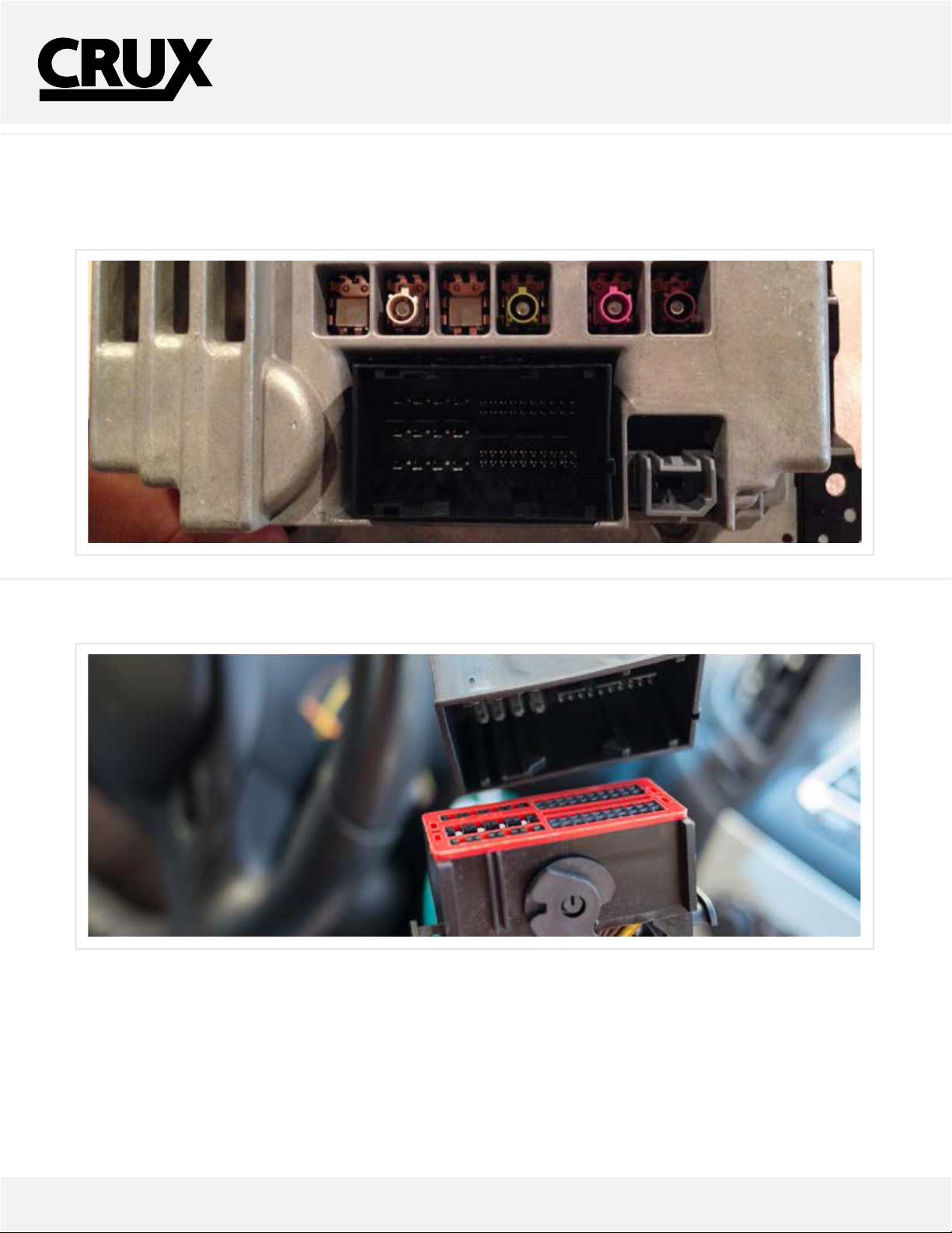
CONNECTING THE INTERFACE
Follow these steps to properly install the CAN module
Step 1 - Remove the factory display to gain access to the factory 52-Pin (RED) connector.
Located behind the display, not the radio. Remove the factory 52-Pin connector.
DODGE & JEEP VEHICLES 2014-UP
RVCCH-75B
Step 2 - Using the provided 52-Pin T-Harness, mate both sides of the harness, to the factory harness and the factory display.
www.cruxinterfacing.comRev. 051016 3
 Loading...