

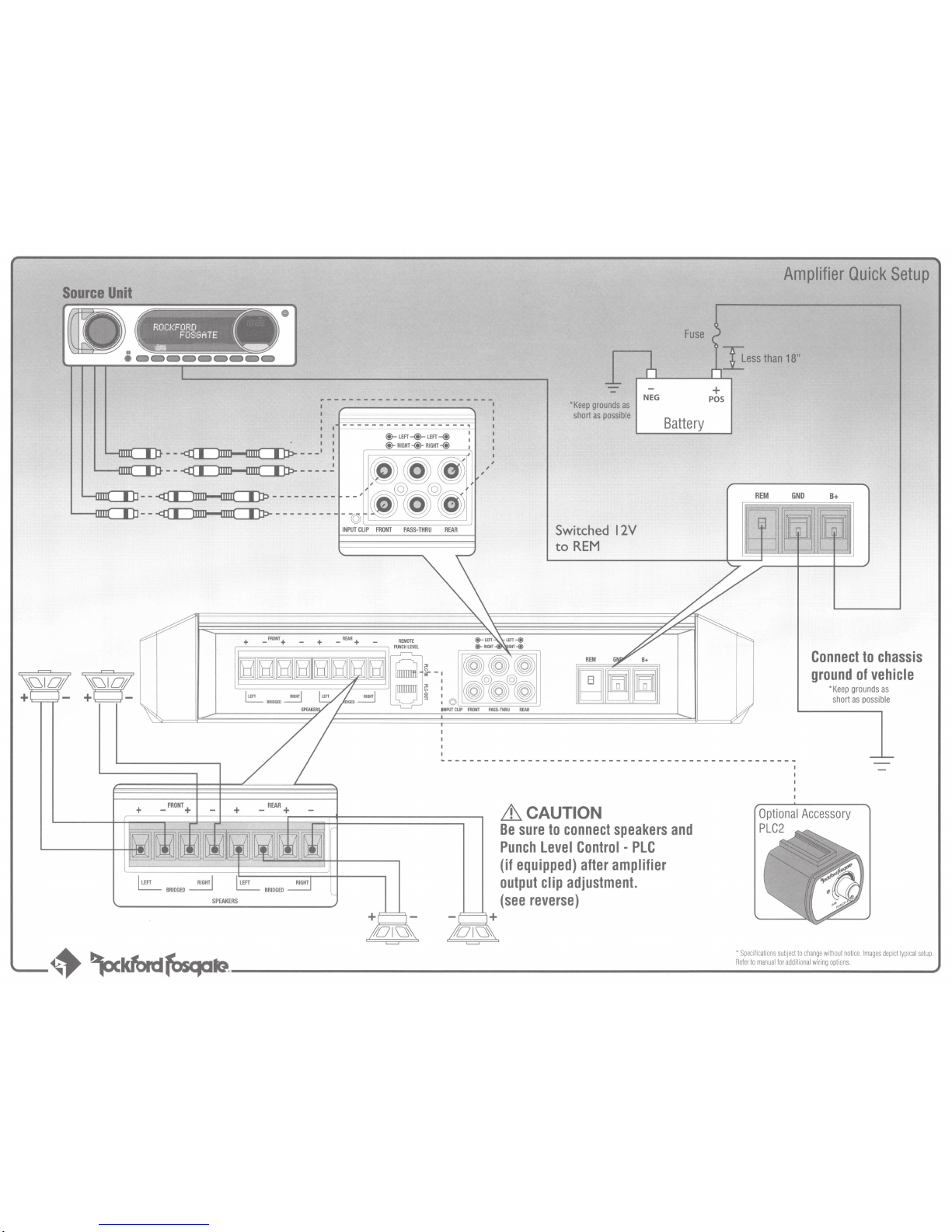
Crutchfield 575PM500X2, Fosgate PM500X2 Quick Setup Manual
Source
Unit
•
~----------------------1
I I
-----------------,
I
@-
LEFT-@-
LEFT-@
1
@-
RIGHT-@-
RIGHT-@
I
-------Jo"
--
~--
-·
l-...fDJIC][)J--
~--
_·_
~
~~--~---------
-------
~----------
-©
INPUT CL':=-
IP
----=F=RoN
=T -PA-
SS--TH-RU
- R-
EAR
___)
,
,
,
*Keep
grounds
as
short
as
possible
Switched
12V
to
REM
REM
NEG
Battery
Amplifier
Quick
Setup
~ess
than
18"
+
POS
REM
GND
B+
Connect
to
chassis
ground
of
vehicle
*
Keep
grounds
as
short
as
possible
~-----------------------------------------------~
+ _FRONT+
+
_REAR+
+
Olu~
i:hCAUTION
Be
sure
to
connect
speakers
and
Punch
level
Control -PlC
(if
equipped)
after
amplifier
output
clip
adjustment.
(see
reverse)
I
-
---~
~~-~~~~~®-------------------------------------------------------------------~
·:sp~ec~ific
:
ati
:
ons
:
su~bje
:
ct:to:cha
:
ng:ew~ith
:
out
:
no~tic
-
e.l
-
ma-ges
-d-
epi
-
ctt
-
ypi
-
cal
-
se-tup
)
.
~...,..
lfAI\I
all
~
~1\ir.
Refer
to
manual
for
additional wiring
options.

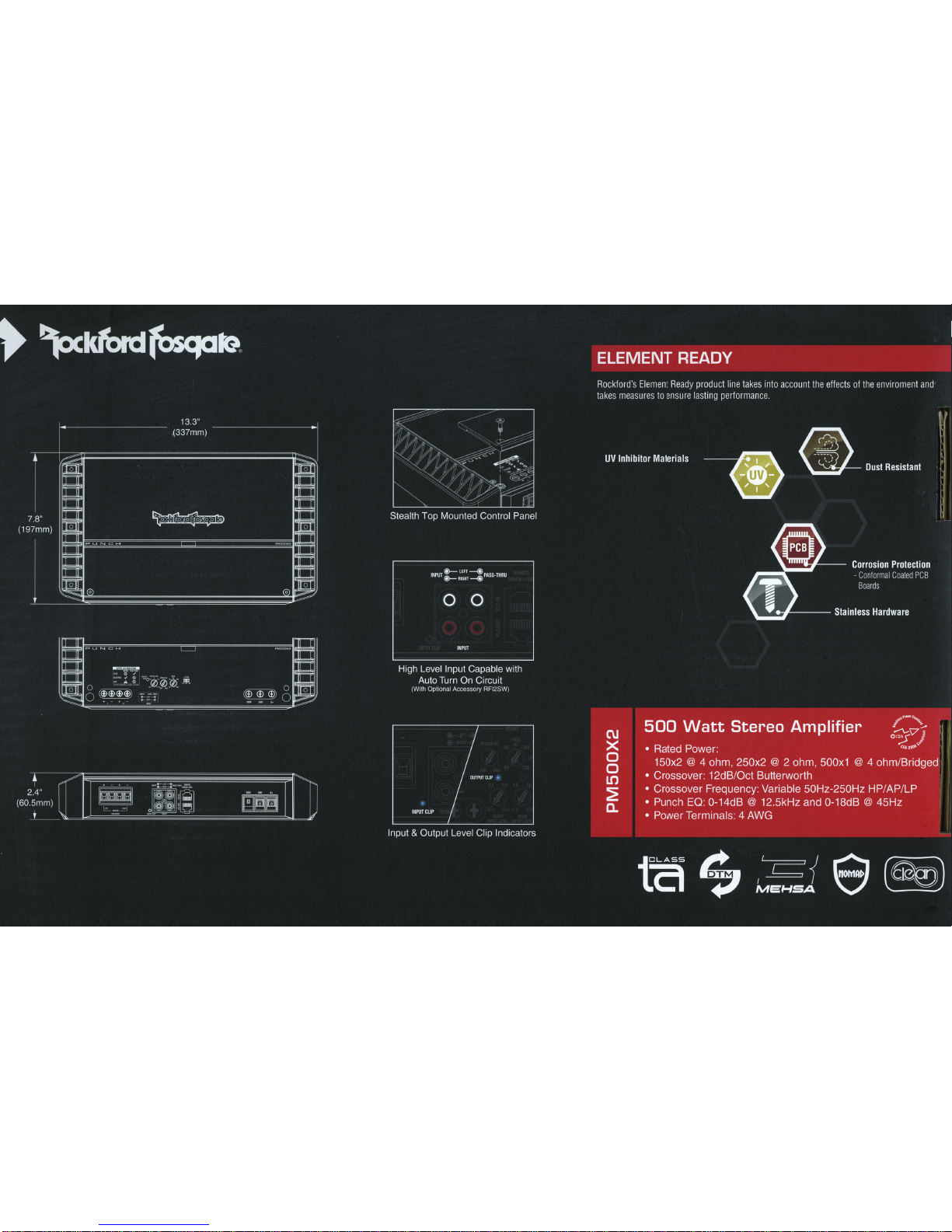
Input
Clip
Indicator
Setup
Be
sure
to
disconnect
all
speakers
from
the
amplifier.
.6CAUTION
Failure
to
comply
may
cause
damage
to
connected
components
and/or
amplifier
.
Increase
the
source
unit
volume
until
the
Input
Clip
Indicator
illuminates
red.
Note:
Input
Clip
can
be
viewed
remotely
with
optional
PLC2.
Decrease
the
source
unit
volume
slightly
until
the
light
turns
completely
off. This
establishes
your
maximum
source
unit
volume
for
adjusting
the
Output
Clip
Indicator
.
Note:
Some
source
units
will
not
clip.
Amplifier
Clip
Indicator
Setup
Insert
test
tone
or
music
CD
to
play
for
setup
.
Adjust
the
Bass & Treble
levels
on
the
source
unit
to
flat.
Be
sure
to
disconnect
Punch
Level
Control -PLC
(if
equipped)
from
the
amplifier.
Note:
Use
the
40Hz@
OdB
tone
(Track
5)
for
mono
amplifier
applications
or
the
1kHz@
OdB
tone
(Track
7)
for
multi-channel
amplifier
applications.
Be
sure
your
x-over
is
switched
to
the
appropriate
filter
setting.
Output
Clip
Indicator
Setup
Turn
the
source
unit
volume
down
.
MUSIC
TESTTONE
'
BLUE
~
./
~r=====
==l
BLUE/REO
./
~
~
.........
;;;;;;;;;;;;;;;
...........................
--!
RED
A
~
~.0..2.0
PLJNC:::H
/i\
(l)
12.0'
·0.
15
INPUTLEVR
v
Adjust
the
Input
Level
knob
until
the
Output
Clip
Indicator
illuminates
to
the
appropriate
color.
Repeat
for
all
channel
levels
of
input.
Reconnect
all
speakers
and
Punch
Level
Control -PLC
(if
F:::::::::::::::~==l
equipped)
to
the
amplifier.
Be
sure
to
maintain
proper
~
speaker
polarity
. V
11111111
--~~~~-------------------------------~
 Loading...