

Crutchfield 000MVGUIDE Installation Manual

2 Replacement Headrest Monitors
3Headrest Mounted Monitors
4Overhead Monitors
5Overhead Monitors with DVD
6Wire Routing
7Wiring Connections
Inside...
Tools Needed: (depending upon vehicle)
000MVGUIDE
Revision 04/29/04
▲
Page
*000MVGuide*
®
Copyright 2004 Crutchfield Corporation
Mobile Video Installation Guide
This installation guide offers examples of mobile video system types and suggested layouts.
The installation of your system will depend upon the make and body style of your vehicle as
well as the equipment purchased.
Flat Blade
Screwdriver
Phillips
Screwdriver
Panel Tool
Pliers
Drill & Bit Set
Utility Knife
Wire Stripper/
Crimp T ool
Torx Driver Set
Socket &
Ratchet Set

MVGUIDE
Replacement Headrest Monitors
2
®
Copyright 2004 Crutchfield Corporation
The components of your mobile video system include a DVD player
(or VCR), a video monitor and a sound component (usually wireless
headphones). The optional Crutchfield wiring kit (available Fall 2004)
has all the parts you’ll need to power these components.
System Layout
A system using replacement headrest monitors is shown with
suggested locations for components and wire routing (Figure 1).
Examine your vehicle to determine the best mounting locations.
Mounting Components
Replacement headrest monitors fit into the same slots in top of the
seat that hold the factory headrests. The wiring is fed through the seat,
to the the floor and routed to the terminal block (Figure 2). Depending
upon the vehicle, the DVD (or VCR) might be mounted under the seat,
under the dash or in the console area. Use the instructions and
hardware supplied with each component to secure them in the desired
locations.
Wire Routing
All system wiring should be concealed for safety and to give your
installation a nice finished look. Wires should be secured so that they
do not interfere with safe vehicle operation. Depending upon the
vehicle, the wiring for your system may need to be run under the dash,
door scuff plate, pillar trimpanel, kickpanel, or headliner. See page 6
for details showing how these trimpanels are typically removed. It will
be necessary to run a power wire to the main fuse panel of the vehicle
(see page 7).
Wiring Connections
The optional Crutchfield wiring kit (available Fall 2004) contains a main
power wire, ground wire, terminal blocks and other accessories for a
making power connections to your vehicle. See a full layout of components on page 7.
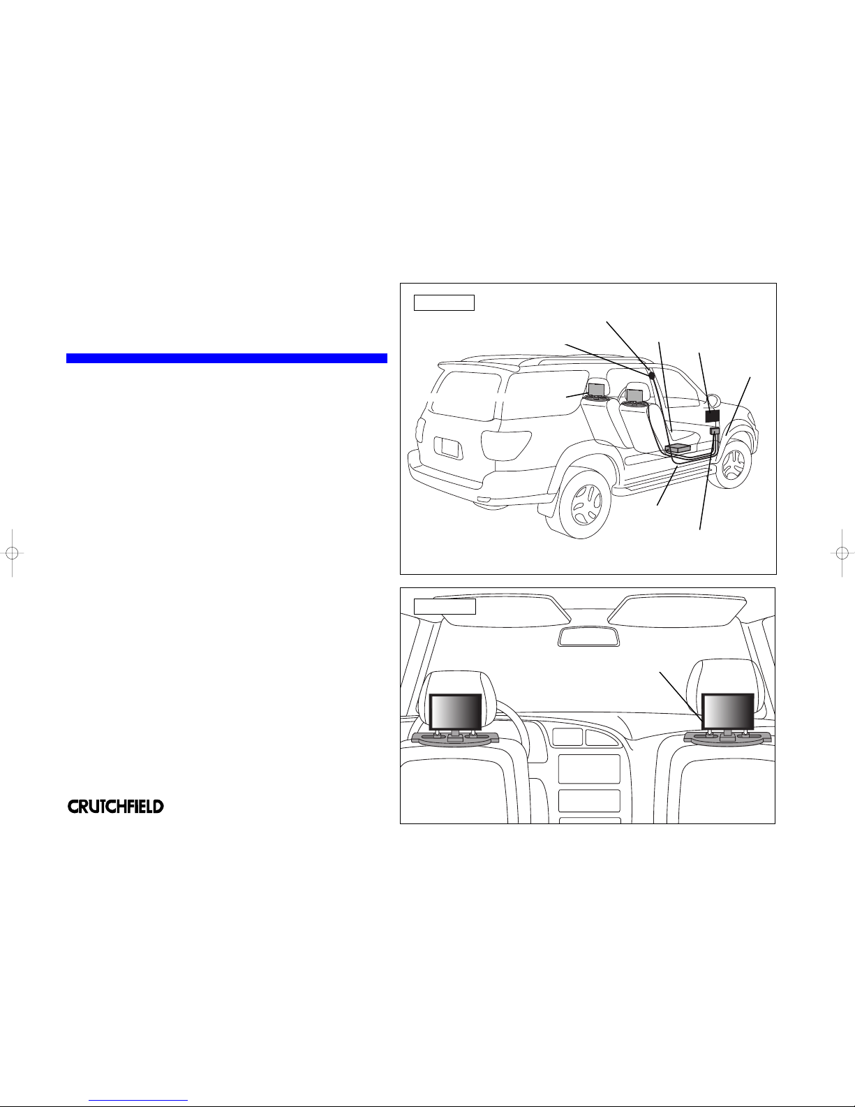
FIGURE 1
Kickpanel
Replacement Headrest Monitors
Scuff Plate
DVD Player
Power Terminal
Wireless Headphone Transmitter
FIGURE 2
The monitor wiring runs
through the seat to the floor.
Fuse Panel
(location depends
upon vehicle)
Pillar Trimpanel
MVGUIDE
Headrest-Mounted Monitors
3
®
Copyright 2004 Crutchfield Corporation
The components of your mobile video system include a DVD player
(or VCR), a video monitor and a sound component (usually wireless
headphones). The optional Crutchfield wiring kit (available Fall 2004)
has all the parts you’ll need to power these components.
System Layout
A system using bracket-mounted headrest monitors is shown with
suggested locations for components and wire routing (Figure 1).
Examine your vehicle to determine the best mounting locations.
Mounting Components
Bracket-mounted headrest monitors secure to most two-post factory
headrests. You simply remove the headrest, side the monitor mounting
bracket through the posts and reinstall the headrest (Figure 2).
Depending upon the vehicle, the DVD (or VCR) might be mounted
under the seat, under the dash or in the console area. Use the
instructions and hardware supplied with each component to secure
them in the desired locations.
Wire Routing
All system wiring should be concealed for safety and to give your
installation a nice finished look. Wires should be secured so that they
do not interfere with safe vehicle operation. Depending upon the
vehicle, the wiring for your system may need to be run under the dash,
door scuff plate, pillar trimpanel, kickpanel, or headliner. See page 6
for details showing how these trimpanels are typically removed. It will
be necessary to run a power wire to the main fuse panel of the vehicle
(see page 7).
Wiring Connections
The optional Crutchfield wiring kit (available Fall 2004) contains a main
power wire, ground wire, terminal blocks and other accessories for a
making power connections to your vehicle. See a full layout of components on page 7.
FIGURE 1
Kickpanel
Bracket Mounted Headrest Monitors
Scuff Plate
DVD Player
Power Terminal
Wireless Headphone Transmitter
FIGURE 2
Pillar Trimpanel
Fuse Panel
(location depends
upon vehicle)
The monitor mounts to the headrest posts
 Loading...