

Crunch PD2100.1, PD3000.1D, PD2000.4, PD4000.4, PD800.2 Quick Start Installation Manual
...Page 1
15 35Hz
SUBSONIC
10 40Hz
SUBSONIC
FULLLPHP
XOVER
MONO STEREO
MODE
SPEAKER OUTPUT
SPEAKER OUTPUT
SPEAKER
LEFT RIGHT
BRIDGED
OUTPUT
SPEAKER
LEFT RIGHT
BRIDGED
OUTPUT
SPEAKER OUTPUT
SPEAKER
LEFT RIGHT
BRIDGED
OUTPUT
SPEAKER OUTPUT
SPEAKER
LEFT RIGHT
BRIDGED
OUTPUT
SPEAKER OUTPUT
SPEAKER OUTPUT
SPEAKER
LEFT RIGHT
BRIDGED
OUTPUT
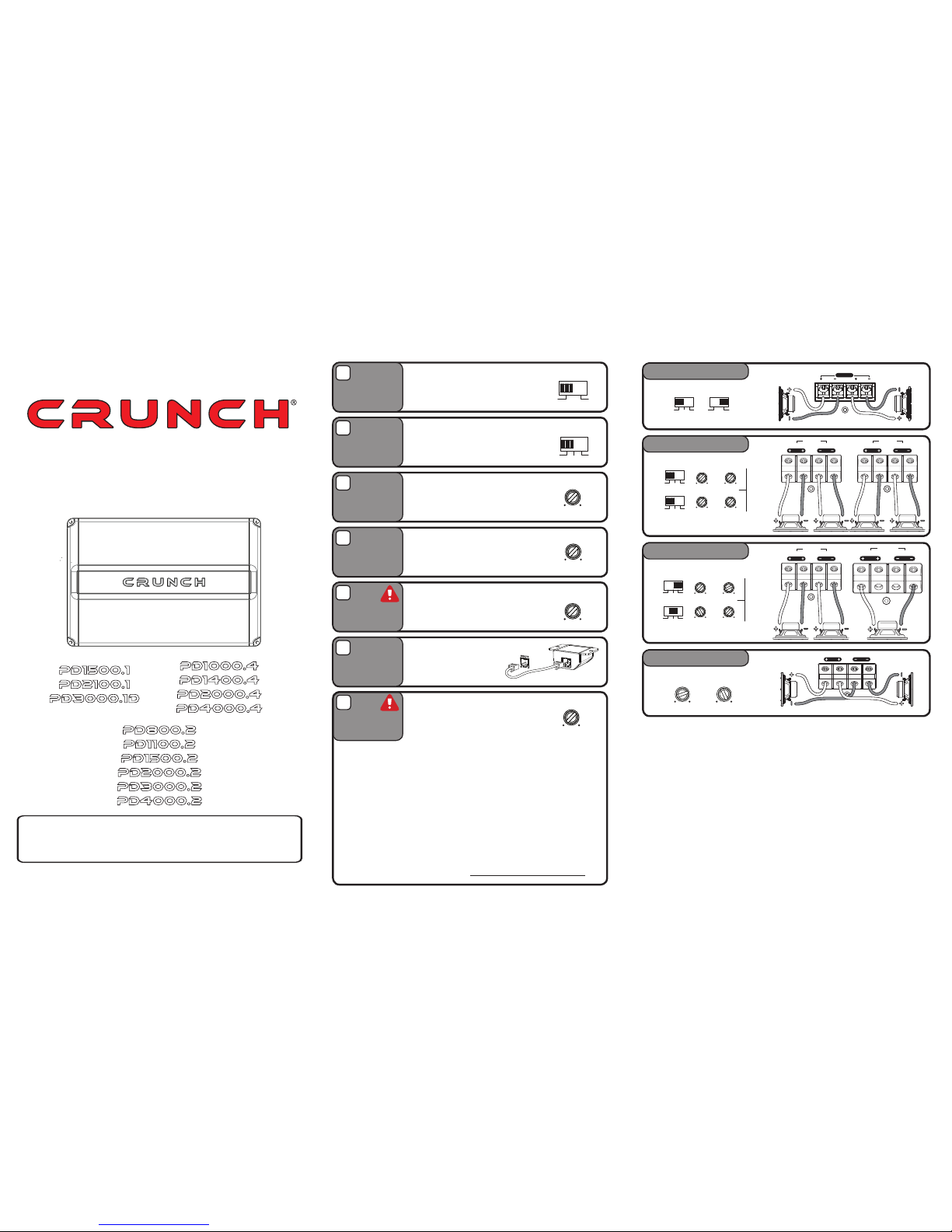
Setup Common System Setup
The input MODE switch will “sum” or
combine the right and left channel signals
in the MONO position to improve bass
performance. Select MONO only when the
amp is being used for subwoofers.
typThe XOVE e switch sets the e R Mod
of crossover that will be active. 4 el chann
models will have two switches, one for each
set of channels.
The HPF(hig ss lter) control will limit the h pa
output below the selected frequency. This
is typically used to protect midrange and hi
frequency speakers from damage and to
allow a smooth transition from a subwoofer.
The LPF(low pass lter) control will limit
output above the selected frequency. This
is used to allow a smooth transition to the
higher frequency speakers.
1. If possible, with the source unit off, conrm that the primary volume control is
is
turned down (counter clockwise).
2. Turn on the source unit (CD, or MP3 player). Re-conrm that the volume
turned down. Make sure the source unit controls; balance, fader, bass and
LED on treble are all set to center or “0” adjustment. Make sure that the green
the end of the amplier is illuminated.
3. Play a clean musical selection of which you are very familiar. CD is preferred.
Do not use radio signals for level setting. Hit play and start turning the volume
of the source unit up.
4. Stop increasing the source unit volume when you reach 3/4 (about 75%) or
until you hear speakers begin to slightly start producing distortion.
5. Increase the amplifier level (clockwise) until distortion is heard, then back
the level down (counter clockwise) until the distortion is eliminated. Small
adjustments may need to be made to balance the levels of multiple amplifiers.
Input Mode
Xover Mode
High pass
Adjustment
Low pass
Adjustment
Bass Boost
Remote Level
Control
2ch - Full Range
ch -4c4 4ch4ch -
Mixedch - c4 4ch4
Mono
A
B
C
D
E
F
The BASS BOOST or BASS EQ control
will increase the output at 45Hz for more
pronounced bass. Exercise caution.
Increase the level in small amounts until
distortion is noticed, then back off a little.
Some models include a bass
remote. Avoid adjusting the bass
remote while operating vehicle.
This is a critical step to insure your amplier
is properly adjusted to match the signal
output level of your source unit.
THIS IS NOT A VOLUME CONTROL!
Level Setting
G
MONO STEREO
MODE
FULL LP PFF H
XOVER
60Hz 1.2KHz
HPF
30Hz 250Hz
LPF
0dB 9dB
BASS
BOOST
6V 0.2V
LEVEL
FULL
LPF HPF
XOVER
MONO STEREO
MODE
FULL
LPF HPF
XOVER
60Hz 1.2KHz
HPF
30Hz 250Hz
LPF
CH 1/2CH 3/4
FULL
LPF HPF
XOVER
0HzHz 6 1.2KHz
HPF
30Hz 250
LPF
FULL
LPF HPF
XOVER
60Hz 1.2KHz
HPF
30Hz 250Hz
LPF
CH 1/2CH 3/4
FULL
LPF HPF
XOVER
60Hz 1.2KHz
HPF
30Hz 250Hz
LPF
SPEAKER
LEFT
RIGHT
BRIDGED
OUTPUT
SPEAKER OUTPUT
15Hz 55Hz
SUB
SONIC
40Hz 150Hz
LOW
PASS
SPEAKER OUTPUT
LEFT RIGHT
BRIDGED
SPEAKER OUTPUT
LEFT RIGHT
BRIDGED
SPEAKER OUTPUT
LEFT RIGHT
BRIDGED
SPEAKER OUTPUT
LEFT RIGHT
BRIDGED
Quick Start
Installation Guide
Congratulations on your choice of a Crunch ampli
er. This
“Quick Start Installation” guide is meant to help you “hook
up” and play music.
Page 2
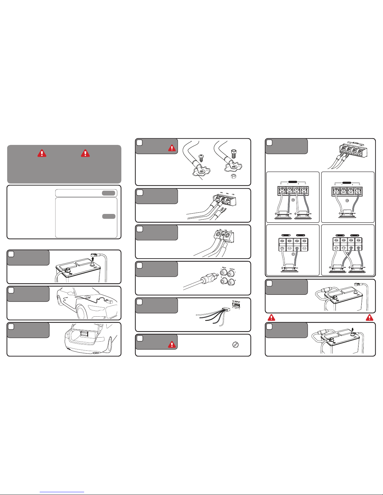
Place terminal in a secure
position so that it won’t
accidentally contact the
negative battery post
Properly route power,
speaker and RCA cables
through the vehicle.
Choose a mounting location
that will provide adequate air
ventilation. Mount the amplier to
a secure surface. Do not mount
the amplier upside down.
Using spade terminals, connect the
+12V to the power cable from the
battery, the REM to the source unit
turn-on wire and the GND to the
chassis ground..
Strip each cable back approx 1/2”,
connect the +12V to the power
cable from the battery, the REM to
the source unit turn-on wire and the
GND to the chassis ground..
Bare metal
Connect the RCA cables to
the INPUT connectors. The
OUTPUT can be used to
provide input for a second
amplier.
cableConnConnectect theect Conn
battery tepositivepositive The
powerpower powerpower cabl
withwithinwitwithin in 18 inches
terminal.
Re-connect the negative
battery terminal making sure it
is securely tightened.
Using spade terminals,connect
the speaker cables the s topeaker c
output connectors. Follow the
best ts your diagram below that
speaker conguration.
The chassis ground connection
is critical to the performance
of the amplier. Choose a
location that is close to the
amplier. Completely scrape
away the paint and use a nut
and bolt if possible.
DO NOT USE AN EXISTING
FACTORY BOLT!
Disconnect
negative battery
terminal
Run Cables
Mount Amplier
Power
Connections
Smaller amps
Signal Input
Low Level RCA
Power
Connections
Larger amps
Signal Input
High Level
Battery Positive
Connection
Re-connect
Negative Battery
Terminal
Speaker
Connections
Chassis Ground
e preparBeB ed Be prepared to disarm s alarm and
o enter your radio / souro ent entertto
Stereo
Power / Ground
cable size
It is critical to use the proper
power and ground cable. Select
the size listed here for your
amplier model. Always use high
quality copper cable.
Cable size recommendations for
multi amp systems are available
on our website.
Installation
Before you start
Monoblock
single woofer Monoblock multiplemultiple
Bridged
CAUTION
Many new and factory radios require a reset code when
disconnected from battery power. This is an anti-theft
feature. Before unplugging power, you must determine if
your radio/source unit requires a reset code. Check the
operation manual for your vehicle or contact the dealer.
1
2
3
5
a
5b
6
7
10
11
9
4
Turn the LEVEL control completely
counter-clockwise to minimum.
The HI INPUT is for use with
source units that do not offer
RCA outputs. Use the supplied
harness to connect to the
source unit’s speaker output.
8
Level Control
6V 0.2V
INPUT
LEVEL
SPEAKER
LEFT
RIGHT
BRIDGED
OUTPUT
SPEAKER OUTPUT
SPEAKER OUTPUT
SPEAKER
LEFT
RIGHT
BRIDGED
OUTPUT
Right + (gray) 4CH REAR
Ch3 Right + (orange)
Ch3 Right - (pink)
Chassis Ground (black)
Ch4 Left + (blue)
Ch4 Left - (yellow)
Connect to factory speater wire directly
Left - (green)
Left + (white)
Right - (brown)
Chassis ground (black)
4ga
8ga
Cable SizeFuse SizeModel
1-30A
1-30A
2-30A
2-30A
2-35A
2-40A
1-30A
2-15A
2-25A
2-40A
2-25A
2-30A
2-40A
PD800.2
PD1100.2
PD1500.2
PD2000.2
PD3000.2
PD4000.2
PD1000.4
PD1400.4
PD2000.4
PD4000.4
PD1500.1
PD2100.1
PD3000.1D
 Loading...