

Page 1

CRUISE CAR, INC.
Cruise Car, Inc. Sarasota Florida 34234 [email protected] Phone: 941-929-1630 Fax: 941-355-6470
OWNER’S MANUAL
M & R SERIES
VECTOR & SUNRAY MODELS
GAS & ELECTRIC
Page 2

Cruise Car, Inc.
5120 Middle Ave. Suite 5 — Sarasota, FL 34234
941-929-1630 or [email protected]
NOTICE
Cruise Car, Inc. is not liable for errors in this manual or for incidental or consequential damages that result from the use of
the material in this manual.
This vehicle conforms to the current American National Standards Institute's Z130 Safety and Performance Requirements for
Golf Cars. This standard, which promotes safety in the design, application, and operation of golf cars, defines a golf car as "a
vehicle used to convey a person or persons and equipment to play the game of golf in an area designated as a golf course."
Throughout this manual, the words "golf car" and "vehicle" are used interchangeably.
The information contained in this document is subject to change without notice.
Cruise Car, Inc. reserves the right to make design changes to vehicles without obligation to make these changes on units
previously sold.
1
Page 3

REGULAR MAINTENANCE ITEMS
PERIODIC MAINTENANCE ITEMS
Engine Oil Filter (286 cc and 351 cc)
Battery (gasoline vehicle)
Engine Air Filter (286 cc and 351 cc)
Spark Plug O.H.V. (286 cc and 351 cc)
Engine Fuel Filter (286 cc and 351 cc)
Spring Tune-Up Kit
Battery Terminal Protector Spray
Battery, 6 x 8-Volt (electric vehicle)
Dry Moly Lube or Equivalent
Battery, 6 x 8-Volt (heavy-duty electric vehicle
Fuse, 10 Amp, Starting Circuit (gasoline vehicle)
Fuse under Seat near Solenoid
Fuse, 15 Amp, Tow/Run Switch (electric vehicle)
Fuse under Seat beneath Electronics Module Cover
Fuse, 10 Amp, Headlight Circuit (if equipped)
Fuse under Seat beneath Electronics Module Cover
Fuse, 0.5 Amp, Brake Light Circuit (if equipped)
Fuse under Floormat beneath Floor Cover Plate
FOREWORD
Thank you for choosing Cruise Car, Inc.. Please protect your investment and ensure that your Cruise Car provides years of
reliable, superior performance by reading and following the maintenance instructions in this manual.
Your comfort and safety are important to us as well, so we urge you to read and follow the step-by-step operating
instructions and safety precautions in this manual. These instructions must be followed in order to avoid the risk of severe
personal injury. If you rent or loan your vehicle to others, we recommend that you ask them to read this manual before they
operate the vehicle.
Cruise Car products are backed by a customer support system designed to offer you fast, courteous service. In the event
that your golf car needs repairs or service, please contact Cruise Car, Inc. we will be able to provide technical advice,
perform warranty work, and sell parts and service manuals. For the name and address of the Cruise Car dealer or distributor
nearest you, call 1-941-929-1630.
We hope you will consider this owner's manual a permanent part of your golf car. If you sell the vehicle, please include the
manual so that the next owner will have the important operating, safety, and maintenance information it contains.
2
Page 4

TABLE OF CONTENTS
Safety Decal and Feature Identification ......................................................................................................................................... 5
Practice Safety ............................................................................................................................................................................... 5
Proposition 65 - State of California ................................................................................................................................................ 5
Safety Details ................................................................................................................................................................................. 6
General Warnings ................................................................................................................................................................ .......... 7
Battery Disconnection .................................................................................................................................................................... 9
General Information ....................................................................................................................................................................... 10
Model Identification ................................................................................................ ........................................................................ 11
Safety Committee .......................................................................................................................................................................... 11
Controls and Indicators - Electric Vehicles ..................................................................................................................................... 12
Controls and Indicators - Gasoline Vehicles .................................................................................................................................. 17
Pre-Operation and Daily Safety Checklist ...................................................................................................................................... 20
Performance Inspection ................................................................................................................................................................. 21
Driving Instructions ........................................................................................................................................................................ 22
Towing ........................................................................................................................................................................................... 25
Transporting on a Trailer ................................................................................................................................................................ 26
Storage - Electric Vehicle ............................................................................................................................................................... 26
Storage - Gasoline Vehicle ................................ ................................................................ ............................................................ 27
Maintenance .................................................................................................................................................................................. 30
Periodic Service Schedules ........................................................................................................................................................... 31
Periodic Lubrication Schedules ...................................................................................................................................................... 35
Vehicle Controller - Electric Vehicles ............................................................................................................................................. 37
Batteries - Electric Vehicles ........................................................................................................................................................... 37
Battery Charger - Electric Vehicles ................................................................................................................................................ 40
Charging Batteries ......................................................................................................................................................................... 41
Single Point Watering System (SPWS).......................................................................................................................................... 43
3
Page 5

Battery - Gasoline Vehicles ............................................................................................................................................................ 45
Engine Oil - Gasoline Vehicles ...................................................................................................................................................... 46
Fueling Instructions - Gasoline Vehicles ........................................................................................................................................ 49
Cleaning the Vehicle ...................................................................................................................................................................... 50
Vehicle Specifications – Electric .................................................................................................................................................... 52
Vehicle Specifications – Gas ......................................................................................................................................................... 53
Corrosion Prevention ..................................................................................................................................................................... 54
Solar Top Maintenance .................................................................................................................................................................. 54
Subsequent Owner Registration .................................................................................................................................................... 54
4
Page 6
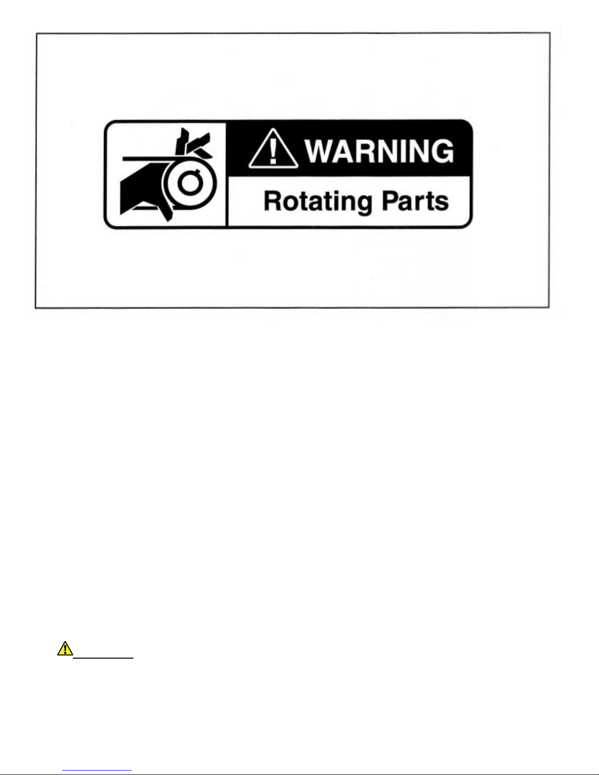
• This product contains or emits chemicals or substances that have been determined by the state of California to
cause cancer and birth defects or other reproductive harm.
PRACTICE SAFETY
Safety signs like you see above may at first seem shocking, but their impact is mild compared with the reality of
severe personal injury.
Your safety and satisfaction are of the utmost importance to us. That is why before operating the vehicle, we
urge you to review the information in this manual. Understand and become familiar with the DANGER,
WARNING, and CAUTION statements and procedures it contains, along with the safety decals that are affixed
to your vehicle.
Take time to understand the language of safety. It is a language that can save your life.
PROPOSITION 65 - STATE OF CALIFORNIA
WARNING
5
Page 7

SAFETY DETAILS
WARNING
• This owner's manual should be read completely before attempting to drive or service the vehicle. Failure to
follow the instructions in this manual could result in property damage, severe personal injury, or death.
It is important to note that some vital statements throughout this manual and on the decals affixed to the vehicle are
preceded by the words DANGER, WARNING, or CAUTION. For your protection, we recommend that you take special notice
of these safety precautions. Safety precautions are essential and must be followed.
Throughout this manual and on the operation and safety decals affixed to the vehicle, the words "golf car" and "vehicle" are
used interchangeably. "Golf car" is defined in the Notice of this manual and no other representation is stated or implied.
If any of the operation or safety decals on the vehicle become damaged, have been removed or cannot be easily read, they
should be replaced immediately to avoid possible property damage, personal injury, or death. Contact your distributor/dealer.
DANGER
• A DANGER indicates an immediate hazard that will result in severe personal injury or death.
WARNING
• A WARNING indicates an immediate hazard that could result in severe personal injury or death.
CAUTION
• A CAUTION with the safety alert symbol indicates a hazard or unsafe practice that could result in minor
personal injury.
CAUTION
• A CAUTION without the safety alert symbol indicates a potentially hazardous situation that could result in
property damage.
6
Page 8

GENERAL WARNINGS
• Battery - Explosive gases! Do not smoke. Keep sparks and flames away from the vehicle and service area.
Ventilate when charging or operating vehicle in an enclosed area. Wear a full face shield and rubber gloves
when working on or near batteries.
The following safety statements must be heeded whenever the vehicle is being operated, repaired, or serviced.
Other specific safety statements appear throughout this manual and on the vehicle.
DANGER
DANGER
• Gasoline - Flammable! Explosive! Do not smoke. Keep sparks and flames away from the vehicle and service
area. Service only in a well-ventilated area.
• Do not operate engine in an enclosed area without proper ventilation. The engine produces carbon monoxide,
which is an odorless, deadly poison.
• The vehicle will not provide protection from lightning, flying objects, or other storm-related hazards. If caught
in a storm while driving a Cruise Car vehicle, exit the vehicle and seek shelter in accordance with applicable
safety guidelines for your location.
WARNING
• Follow the procedures exactly as stated in this manual, and heed all DANGER, WARNING, and CAUTION
statements in this manual as well as those on the vehicle and battery charger.
• Do not leave children unattended on vehicle.
• Prior to leaving the vehicle unattended or servicing the vehicle, set the park brake, place the
Forward/Reverse handle or switch in the NEUTRAL position, turn the key switch to the OFF position, and
remove the key. Chock the wheels when servicing the vehicle.
• Improper use of the vehicle or failure to properly maintain it could result in decreased vehicle performance,
severe personal injury, or death.
• Any modification or change to the vehicle that affects the stability or handling of the vehicle, or increases
maximum vehicle speed beyond factory specifications, could result in severe personal injury or death.
• Check the vehicle for proper location of all vehicle safety and operation decals and make sure they are in
place and are easy to read.
• Only trained technicians should service or repair the vehicle or battery charger. Anyone doing even simple
repairs or service should have knowledge and experience in electrical and mechanical repair. The
appropriate instructions must be used when performing maintenance, service, or accessory installation.
• Wear safety glasses or approved eye protection when servicing the vehicle or battery charger. Wear a full
face shield and rubber gloves when working on or near batteries.
• Do not wear loose clothing or jewelry such as rings, watches, chains, etc., when servicing the vehicle or
battery charger.
• Use insulated tools when working near batteries or electrical connections. Use extreme caution to avoid
shorting of components or wiring.
Electric vehicle only:
7
Page 9

• Place Tow/Run switch in the TOW position before disconnecting or connecting the batteries. Failure to
heed this warning could result in a battery explosion or severe personal injury.
• To avoid unintentionally starting the vehicle, disconnect the batteries as shown. See Battery Disconnection
on page 9.
• After disconnecting the batteries, wait 90 seconds for the controller capacitors to discharge.
Gasoline vehicle only:
• To avoid unintentionally starting the vehicle:
• - Disconnect battery cables, negative (-) cable first (Figures 2,3,4,5).
8
Page 10

WARNING
• Disconnect the spark plug wire from the spark plug.
• Frame ground - Do not allow tools or other metal objects to contact frame when disconnecting battery
cables or other electrical wiring. Do not allow a positive wire to touch the vehicle frame, engine, or any
other metal component.
BATTERY DISCONNECTION
Refer to the following figures for correct battery disconnection information for your vehicle
9
Page 11

GENERAL INFORMATION
Cruise Cars are available with either electric or gasoline power. Throughout this manual, important features unique to each
model are highlighted. We urge the owner/operator to read and understand this manual, and to pay special attention to the
features specific to his/her vehicle(s).
10
Page 12
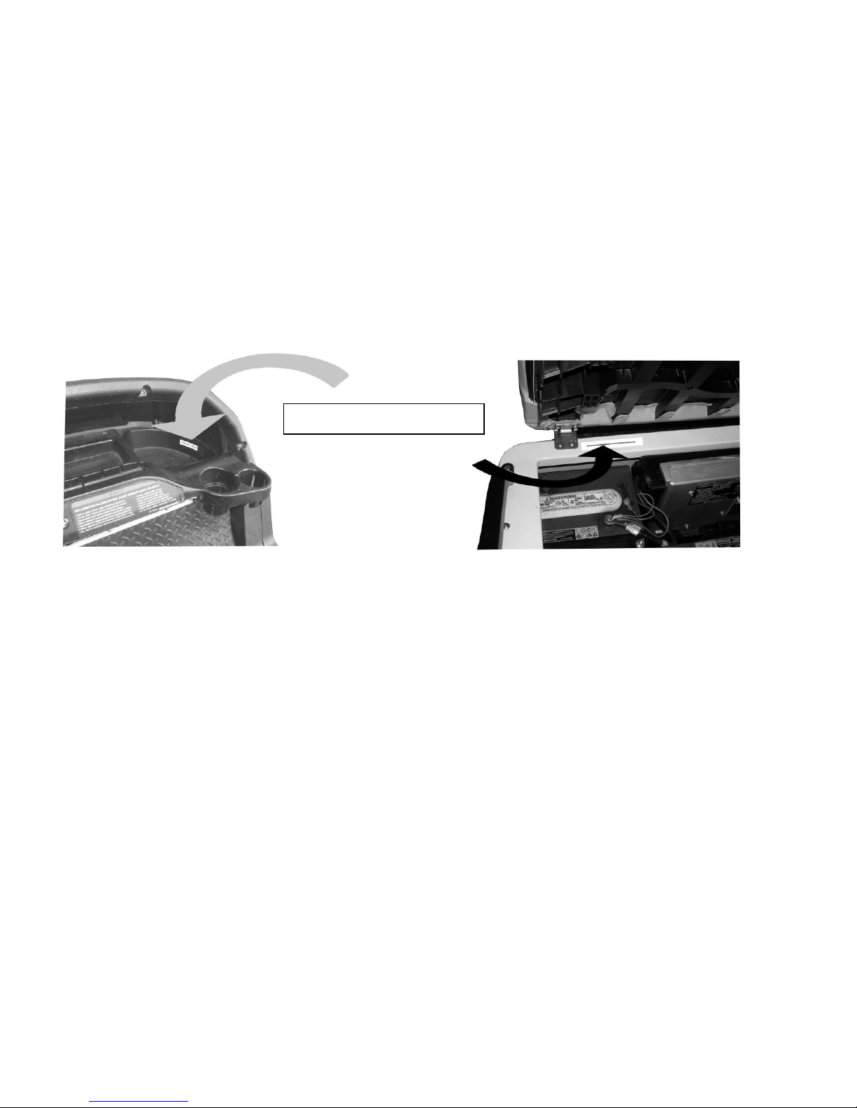
Figure 6.1 – Serial Number Decal
Figure 6.2 – Serial Number Decal
# # # # # # # # # # # # #
MODEL IDENTIFICATION
The serial number of your Cruise Car is printed on a label located in front of the passenger foot well above the dash, or
underneath the driver side seat on the edge of the seat pedestal. (Figure 6.1 and 6.2)
NOTE: Have the vehicle serial number available when ordering parts or making inquiries.
SAFETY COMMITTEE
If the cart is to be rented or is part of a fleet, we strongly recommend that a safety committee be appointed. One of the main
concerns of this committee should be the safe operation of the golf cars.
This should include at a minimum:
• Where golf cars should be driven.
• Ensuring that proper warnings of driving hazards are displayed and visible.
• Who should and who should not drive golf cars.
• Instructing first time drivers.
• Maintaining golf cars in a safe driving condition.
• How various rules are to be enforced.
11
Page 13

CONTROLS AND INDICATORS - ELECTRIC VEHICLES
See General Warnings on page 7.
WARNING
• If renting or loaning the vehicle, make sure the driver is familiar with all controls and operating procedures
before allowing the vehicle to be driven.
• Do not shift the Forward/Reverse switch while the vehicle is moving. To avoid injury to an unsuspecting
passenger or damage to the vehicle, always bring the vehicle to a full stop before shifting the
Forward/Reverse switch.
• Release the accelerator pedal and then press the brake pedal firmly until the vehicle stops. To avoid
unintentionally starting or rolling the vehicle, set the park brake, place the Forward/Reverse switch in the
NEUTRAL position, turn the key switch to the OFF position, and remove the key when leaving the vehicle.
KEY SWITCH
The key switch is mounted on the dash to the right of the steering column (Figure 7). It has two positions, OFF and ON,
which are clearly labeled. See following NOTE.
FORWARD/REVERSE CONTROL
The Forward/Reverse rocker switch is located on the seat support panel, below and to the right of the driver's
right knee (Figure 8). The F (FORWARD) and R (REVERSE) are clearly marked. Push down the FORWARD
side of the switch to operate the vehicle in the forward direction, or push down the REVERSE side of the switch
to operate the vehicle in reverse. When the rocker switch is positioned in the NEUTRAL position, with neither
side down, the vehicle will not operate if the accelerator pedal is pressed. The reverse buzzer will sound as a
warning when the Forward/Reverse switch is in the REVERSE position
12
Page 14

ACCELERATOR PEDAL
• Walk away braking will not limit vehicle speed to 1 mph (1.6 km/h) on very steep grades.
Do not operate vehicle on slopes exceeding 20% grades.
Excel System Vehicles
• Motor Braking:This feature helps to control vehicle downhill speed. When traveling downhill, motor braking engages to
maintain speeds proportional to the accelerator pedal position. For example, when the accelerator is fully pressed, motor
braking holds the vehicle at the programmed top speed. When the accelerator pedal is fully released, motor braking slows the
vehicle to a complete stop or allows the vehicle to coast freely, depending upon the selected controller setting. This feature is
selectable. Contact your dealer/distributor to inquire about this feature.
IQ System Vehicles
• Pedal Up Motor Braking: When vehicle speed is above 11 mph (17.7 km/h), releasing the accelerator pedal will activate
motor braking, which slows the vehicle speed. Once vehicle speed slows to below approximately 11 mph (17.7 km/h), with the
accelerator pedal still released, motor braking will be deactivated and the vehicle will coast freely. This feature is selectable.
Contact your dealer/distributor to inquire about this selectable feature.
• Pedal Down Motor Braking: This feature helps to control vehicle downhill speed. Motor braking is activated when the
vehicle reaches the programmed top speed and holds the vehicle at that speed. Motor braking is automatically disengaged
when vehicle speed slows below the programmed top speed.
The accelerator pedal is the pedal on the right, with the word GO molded into it (Figure 9). The operation of the accelerator
pedal differs from that of an automobile. When the key switch is the ON position, and the Forward/Reverse switch is in either
the FORWARD or REVERSE position, pressing the accelerator pedal will automatically release the park brake and start the
vehicle moving in the direction selected (forward or reverse). As the accelerator pedal is pressed, speed will increase until
full speed is reached. When the accelerator is released, power will be cut off and the motor will stop running.
Electric vehicles use a special electrical system, which employs motor braking in some modes of operation. In those
modes, the vehicle operates as follows:
• Walk Away Braking: This feature prevents the vehicle from rolling away uncontrolled should the driver park on a slope
and leave the vehicle without locking the park brake. The vehicle will roll at about 1 mph (1.6 km/h). If the walk away
braking function remains engaged for two seconds or more, a warning buzzer will sound to alert the driver that motor
braking has been activated. See following WARNING.
WARNING
13
Page 15
BRAKE PEDAL
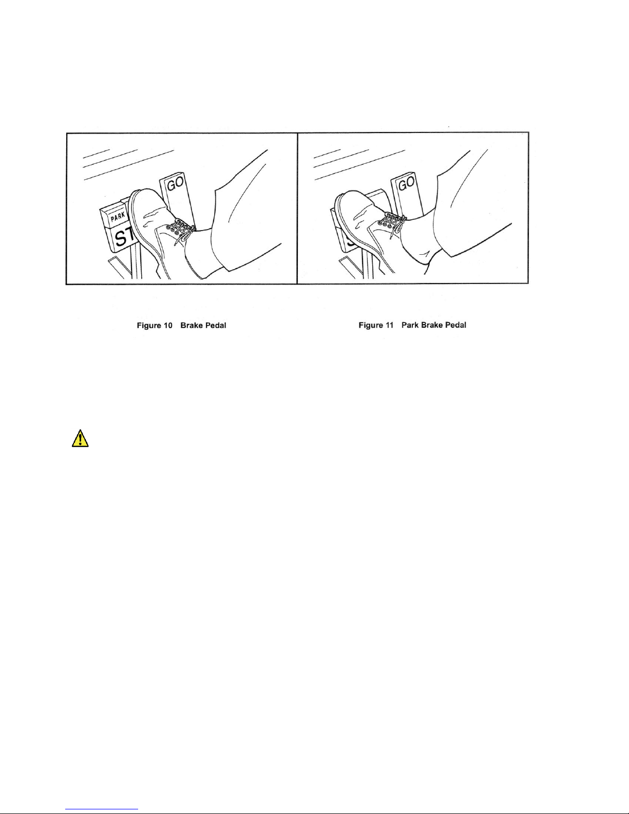
The brake pedal is the large pedal on the left with the word STOP molded into it. To slow or stop the vehicle, press the brake
pedal with your foot (Figure 10).
PARK BRAKE PEDAL
The park brake pedal is the small raised portion in the upper left corner of the brake pedal. It has the word PARK molded
into it. To set the park brake, press the brake pedal firmly and tilt the park brake portion of the pedal forward with your foot
(Figure 11). See following WARNING and NOTE.
WARNING
• The park brake will release automatically when either the accelerator or brake pedal is pressed. The park
brake has multiple locking positions and should be firmly pressed and locked to prevent the vehicle from
rolling.
NOTE: Vehicles equipped with lights: After the park brake is engaged, the brake lights will remain illuminated for up to
four minutes.
14
Page 16
BATTERY WARNING LIGHT
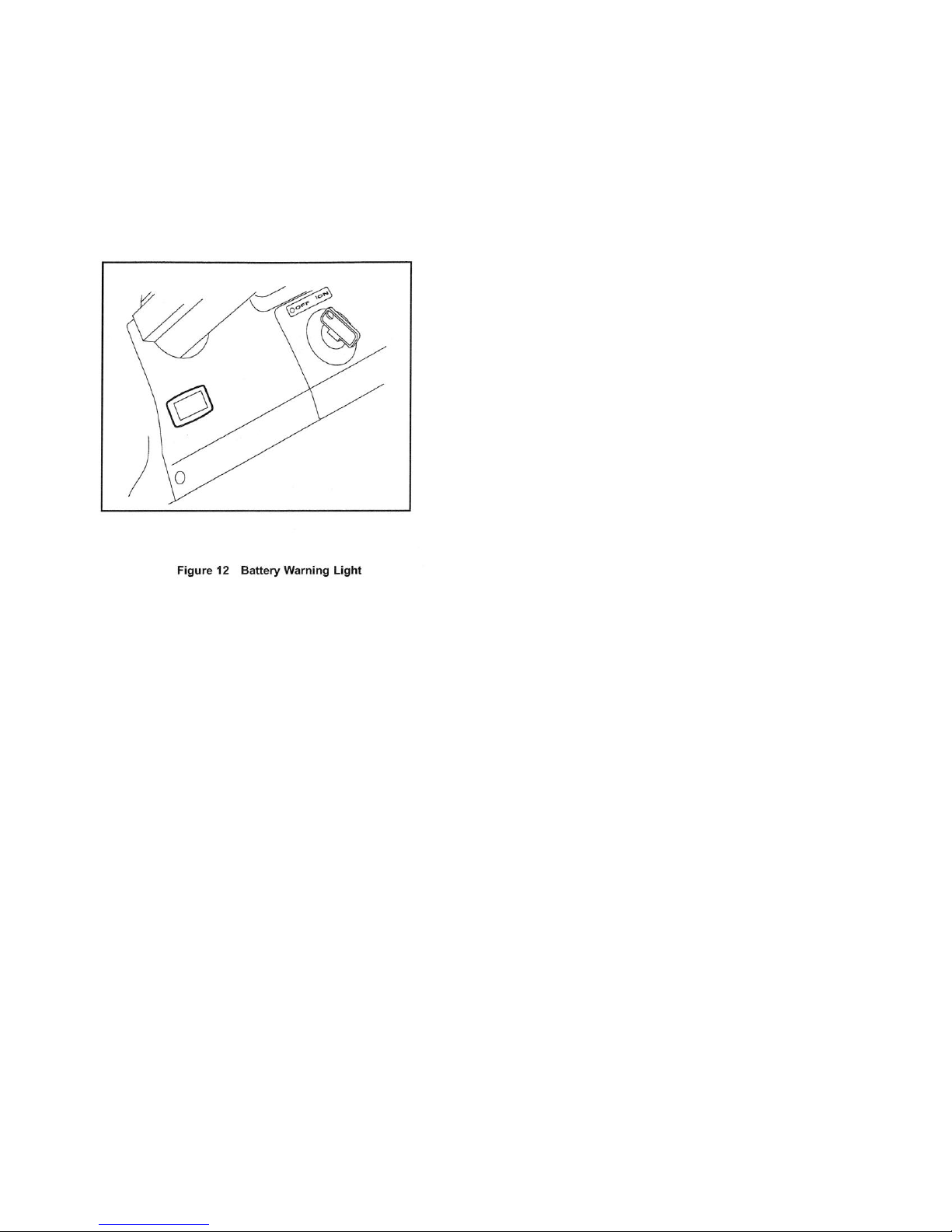
Some electric vehicles are equipped with a dash-mounted warning light (below the steering column) that, when the vehicle is
in operation, indicates low battery voltage or, when the vehicle is being charged, indicate a charging problem (Figure 12).
The battery warning light is controlled by the onboard computer (if so equipped).
When the vehicle is in operation, the warning light is controlled by the onboard computer (if so equipped).
• Batteries' voltage drops below 48 volts when there is no load on the batteries (the vehicle is stopped and there are no
accessories on).
• Batteries have discharged to less than 25% of rated capacity.
If the warning light illuminates when the vehicle is operating, there will be enough power remaining to drive the vehicle for
approximately 30 minutes. However, the vehicle should be charged at the first opportunity. If the warning light illuminates
and the vehicle is unable to operate for 30 minutes, have your cart checked for a possible battery or electrical system
problem.
When the batteries receive an incomplete charge because 1) the DC power cord is disconnected, 2) AC power to the
charger is interrupted, 3) automatic charger shut-off occurs after 16 hours of operation, 4) the charger malfunctions, or 5) the
wrong charger is used, the warning light will indicate as follows:
• The warning light will not illuminate if the charge is 90% or more complete. The onboard computer (if equipped) will retain
in memory the amount of charge needed to fully replenish the batteries and will complete the charge during the next
charge cycle.
• When the charger is unplugged, the warning light will illuminate and remain illuminated for 10 seconds if the charge is less
than 90% complete but the vehicle has enough power for approximately 30 minutes of operation. This will alert the
operator that the vehicle may be used, but that it must be charged to completion as soon as possible.
• The warning light will repeatedly illuminate for 10 seconds, with 4 second intervals if the charger times out at 1.6 hours and
the batteries are not sufficiently charged. This indicates an abnormal charge cycle. The charger and batteries should be
checked.
• The warning light will repeatedly illuminate for 10 seconds, with 4 second intervals during a charge cycle (DC plug is still
connected) if AC power to the charger is interrupted. The light will go out when AC power is restored.
15
Page 17
TOW/RUN SWITCH
WARNING
• Place Tow/Run switch in the TOW position before disconnecting or connecting the batteries. Failure to
heed this warning could result in a battery explosion or severe personal injury.
• When the Tow/Run switch is in the TOW position, all motor braking functions, including walk away braking,
are disabled.
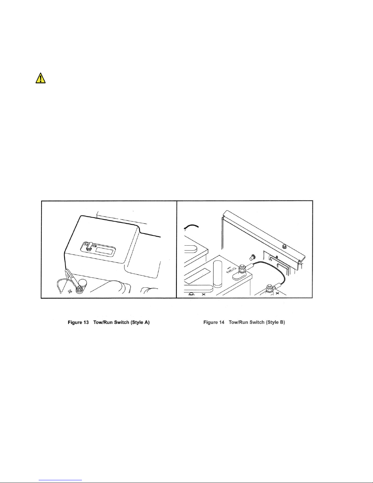
Electric vehicles are equipped with a Tow/Run switch, located under the seat between the batteries (Figure 13) or (Figure
14). The switch must be in the RUN position in order to operate the vehicle. When the switch is in the TOW position, power
to the vehicle electrical components is turned off and the vehicle will not operate. See following NOTE.
NOTE: After placing the Tow/Run switch in the TOW position, allow 10 seconds to elapse before switching back to the
RUN position.
After placing the Tow/Run switch in the RUN position, allow 10 seconds to elapse before operating the vehicle.
The Tow/Run switch should be placed in the TOW position under the following conditions:
• Before Towing the Vehicle: Place the Tow/Run switch in the TOW position to disable all motor braking functions, thus
preventing possible damage that could occur to the vehicle or electrical components if the vehicle is towed while the walk
away braking motor braking function is operating.
• Before Disconnecting or Connecting Battery Cables: Place the Tow/Run switch in the TOW position to turn off power
to the vehicle electrical system, thus preventing severe arcing and possible battery explosion as the battery cables are
disconnected.
• For Long Term Storage: Place the Tow/Run switch in the TOW position to turn off power to the vehicle electrical system,
thus preventing vehicle electrical components from discharging the batteries.
16
Page 18
CONTROLS AND INDICATORS - GASOLINE VEHICLES
See General Warnings on page 7.
WARNING
• If renting or loaning the vehicle, make sure the driver is familiar with all controls and operating procedures
before allowing the vehicle to be driven.
• Do not shift the Forward/Reverse handle while the vehicle is moving. To avoid injury to an unsuspecting
passenger or damage to the vehicle, always bring the vehicle to a full stop before shifting the
Forward/Reverse handle.
• Release the accelerator pedal and then press the brake pedal firmly until the vehicle stops. To avoid
unintentionally starting or rolling the vehicle, set the park brake, place the Forward/Reverse handle in the
NEUTRAL position, turn the key switch to the OFF position, and remove the key.
• Do not tamper with the governor. Doing so will void the warranty, as well as damage the engine and other
components, and could result in property damage, personal injury, or death due to unsafe speed.
KEY SWITCH
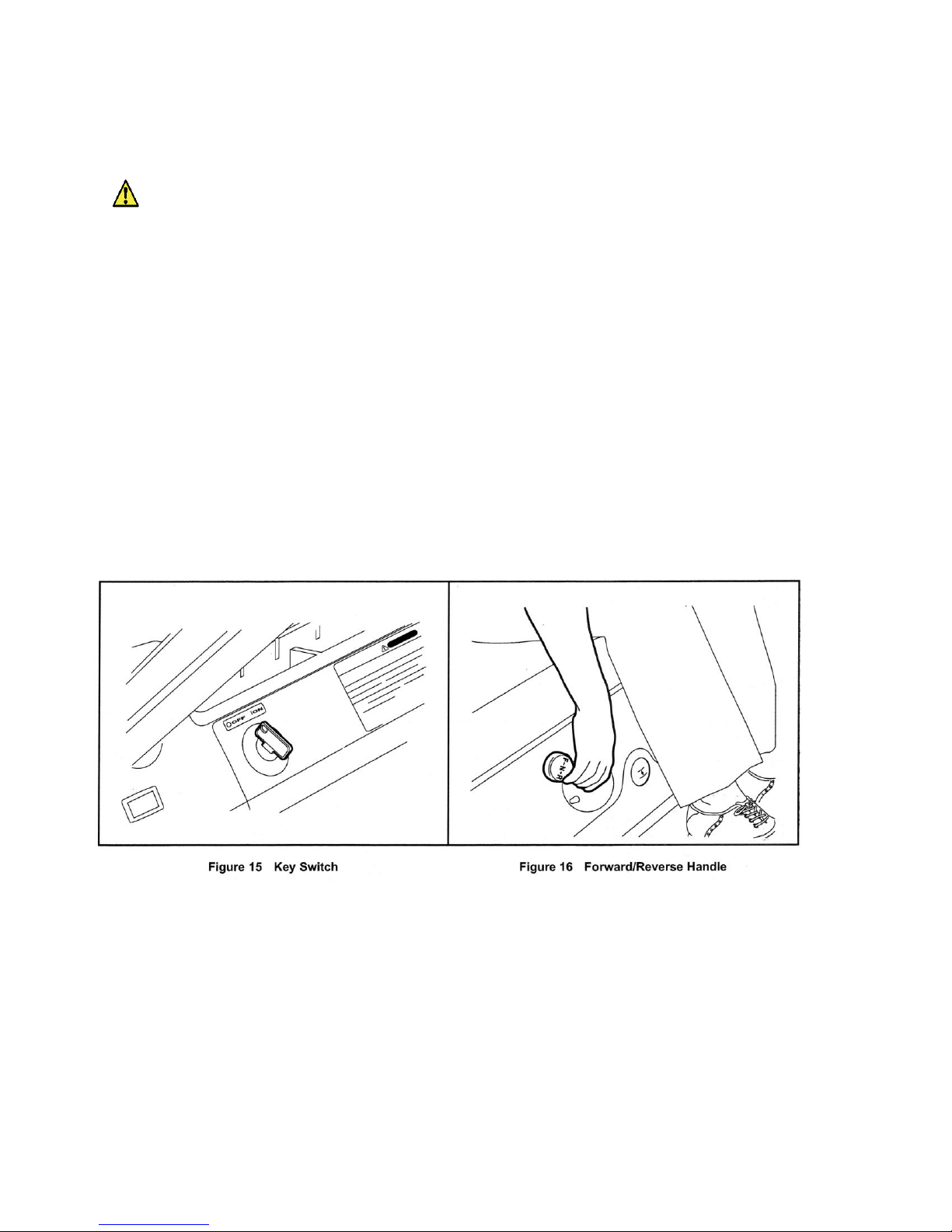
The key switch is mounted on the dash to the right of the steering column (Figure 15). It has two positions, OFF and ON,
which are clearly labeled. See following NOTE.
NOTE: The key can be removed only when the key switch is in the OFF position.
FORWARD/REVERSE CONTROL
The Forward/Reverse handle is located on the seat support panel, below and to the right of the driver's right knee (Figure
16). The handle has three distinct positions: F (FORWARD), N (NEUTRAL), and R (REVERSE). Rotate the handle towards
the driver (FORWARD) to operate the vehicle in the forward direction, or towards the passenger (REVERSE) to operate the
vehicle in reverse. When the handle is in the straight up position, (NEUTRAL), the vehicle will not operate. The engine will
stop if it is shifted to this position during operation. Our vehicles operate at reduced speed in reverse. The reverse buzzer will
sound as a warning when the Forward/Reverse handle is in the REVERSE position.
17
Page 19
ACCELERATOR PEDAL
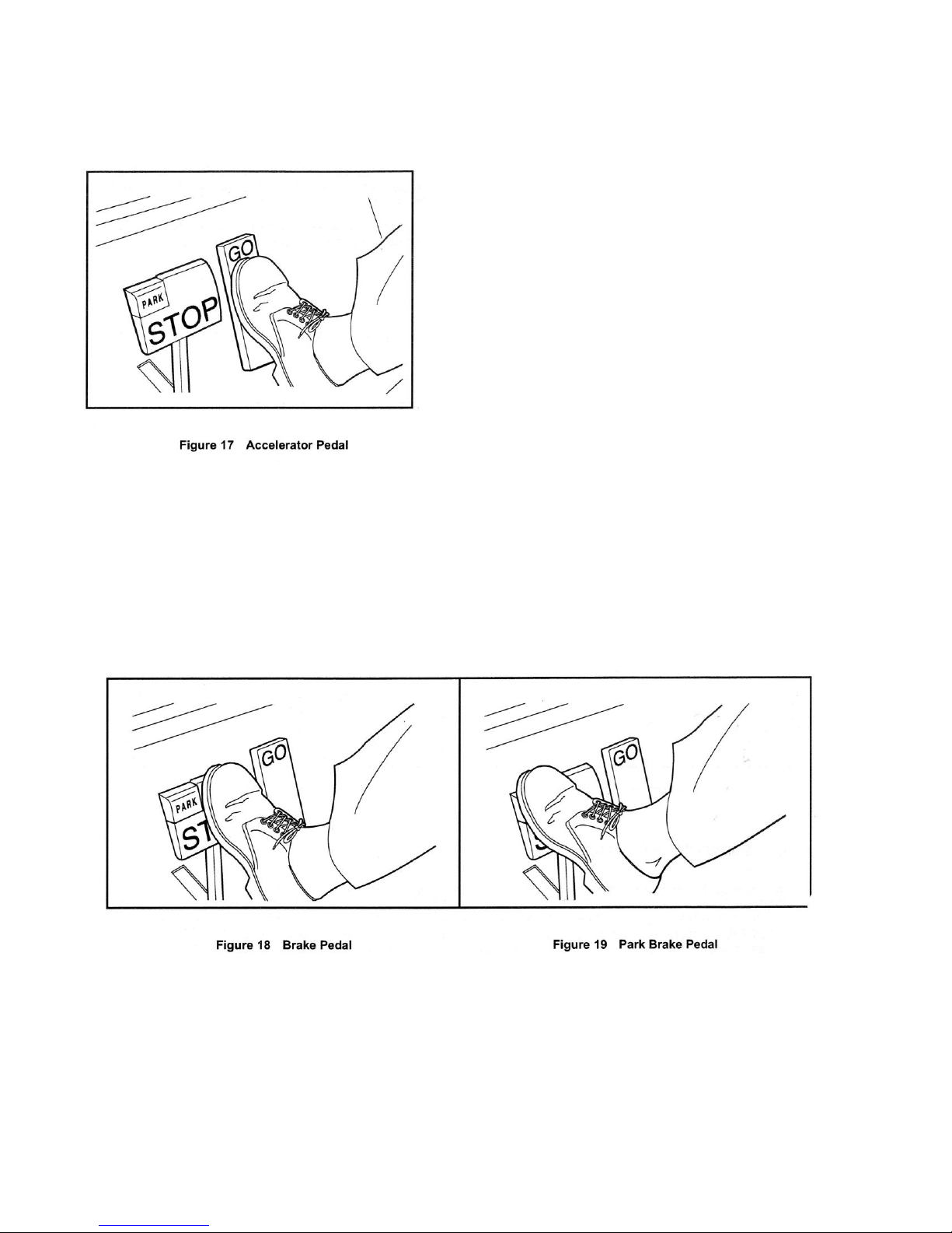
The accelerator pedal is the pedal on the right, with the word GO
molded into it (Figure 17). The operation of the accelerator pedal
differs from that of an automobile. When the key switch is in the ON
position, and the Forward/Reverse handle is in either the
FORWARD or REVERSE position, pressing the accelerator pedal
will automatically release the park brake and start the vehicle
moving in the direction selected (forward or reverse). As the
accelerator pedal is pressed, speed will increase until full speed is
reached. When the accelerator is released, power will be cut off and
the motor will stop running
BRAKE PEDAL
The brake pedal is the large pedal on the left with the word STOP molded into it. To slow or stop the vehicle, press the brake
pedal with your foot (Figure 18).
PARK BRAKE PEDAL
The park brake pedal is the small raised portion in the upper left corner of the brake pedal. It has the word PARK molded into
it. To set the park brake, press the brake pedal firmly and tilt the park brake portion of the pedal forward with your foot
(Figure 19). See following WARNING and NOTE.
18
Page 20
WARNING
• With the cam in the MAINTENANCE position and the engine running, the vehicle may move suddenly if the
Forward/Reverse handle is shifted or accidentally bumped. To prevent this, chock the front and rear wheels and
firmly set the park brake before servicing or leaving the vehicle.
NOTE: Be sure to return the cam to the OPERATE position after servicing the vehicle, or it will not operate with the
Forward/Reverse handle in either the FORWARD or REVERSE position.
• The park brake will release automatically when either the accelerator or brake pedal is pressed. The park
brake has multiple locking positions and should be firmly pressed and locked to prevent the vehicle from
rolling.
NOTE: Vehicles equipped with lights: After the park brake is engaged, the brake lights will remain illuminated for up to
four minutes.
NEUTRAL LOCKOUT
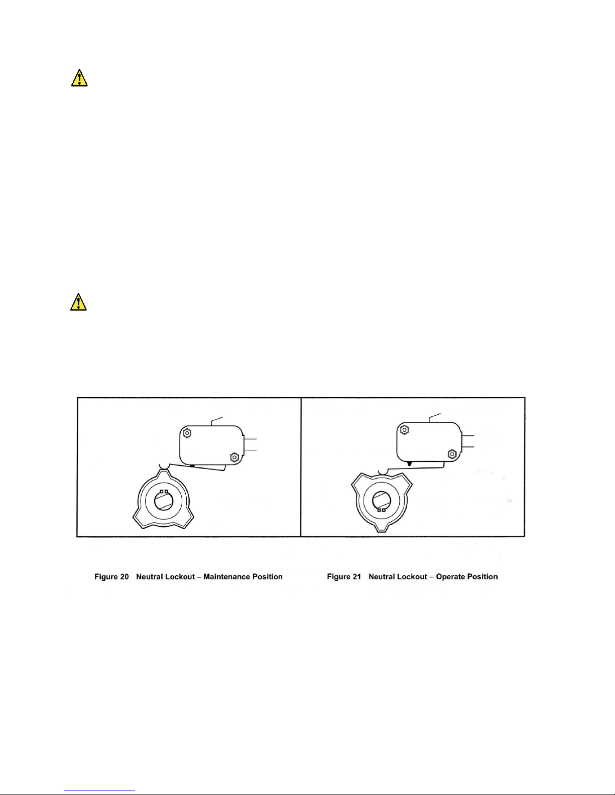
For the convenience of the trained technician, there is a neutral lockout cam located on the back of the Forward/Reverse
shifter. If the neutral lockout cam is pulled out approximately 3/8 inch (10 mm) and then rotated one-half turn until it snaps
into place, the cam will be in the MAINTENANCE position (Figure 20). This will allow the technician to operate the engine in
neutral for certain maintenance procedures. With the cam in this position, the vehicle will not operate if the Forward/Reverse
handle is placed in either the FORWARD or REVERSE position.
To put the cam back into the OPERATE position, pull the cam out approximately 3/8 inch (10 mm) and rotate it one-half turn
until it snaps into place (Figure 21). See following WARNING and NOTE.
WARNING
19
Page 21
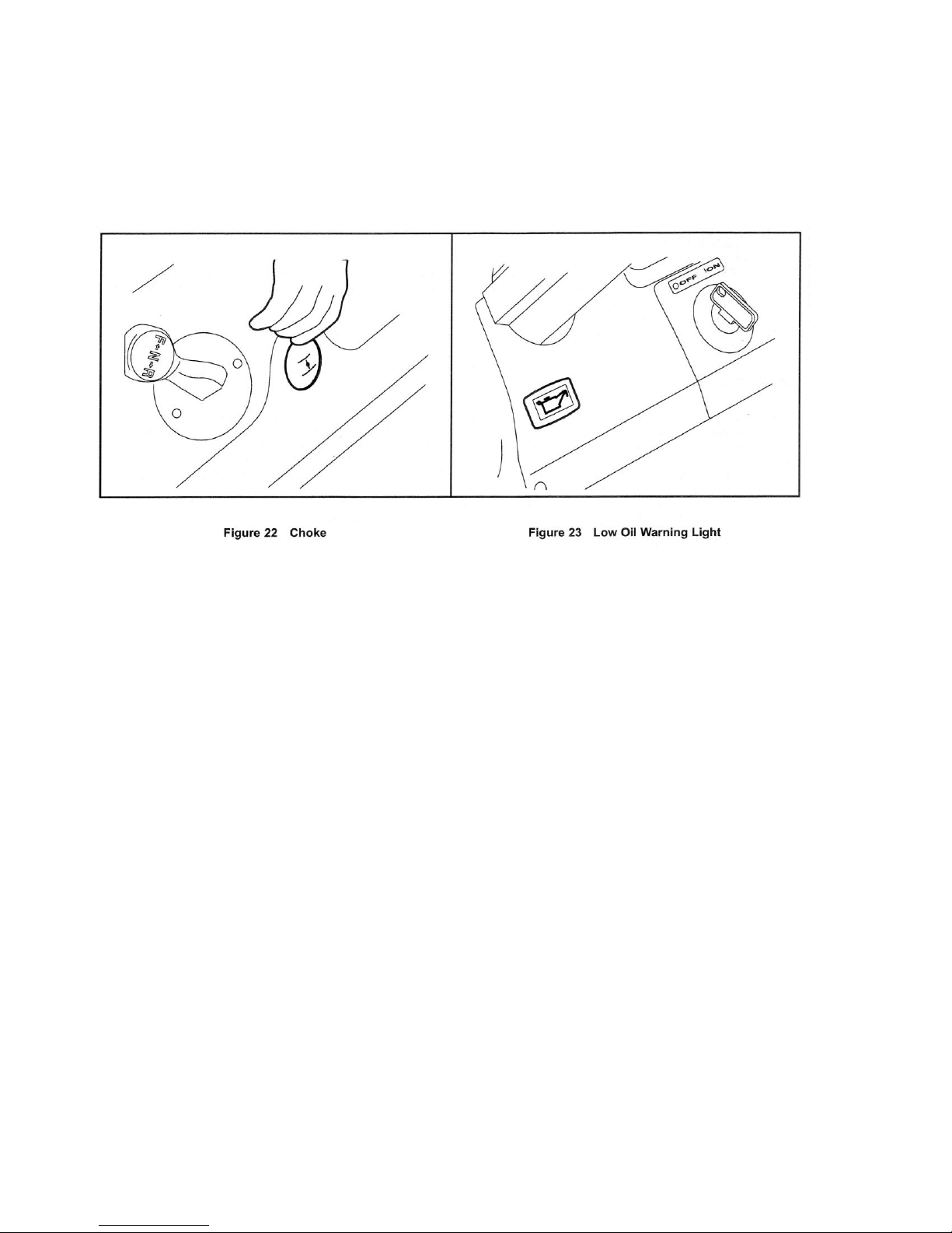
CHOKE
The choke is located on the seat support panel below and to the right of the driver's right knee (Figure 22). If the vehicle is
hard to start in cool or cold temperatures, simply push in the choke cover to activate it. Hold it during start up and release the
choke cover after the engine starts and runs smoothly.
LOW OIL WARNING LIGHT
The gasoline golf car is equipped with a low oil warning light, located on the dash panel just below the steering column
(Figure 23). If the warning light comes on, oil should be checked and added to the engine as necessary before continuing to
use the vehicle. The vehicle should never be driven with the low oil warning light remaining on. If the warning light goes on
and off, you may proceed, but oil should be added at the first opportunity. If the oil level is correct and the warning light stays
on, have a trained technician check the vehicle. See following CAUTION.
CAUTION
Failure to add oil immediately when the low oil warning light stays on may result in permanent engine
damage
PRE-OPERATION AND DAILY SAFETY CHECKLIST
Each vehicle has been thoroughly inspected and adjusted at the factory; however, upon receiving your new vehicle(s), you
should become familiar with its controls, indicators, and operation. Carefully inspect each vehicle to ensure that it is in proper
working condition before accepting delivery.
Use the following checklist as a guide to inspect the vehicle. This checklist should be used daily to ensure that the vehicle is
in proper working condition and in conjunction with the Performance Inspection, and the Periodic Service Schedules on page
31. Any problems should be corrected by a trained technician.
Any vehicle not functioning correctly should be removed from use until it is properly repaired. This will prevent further
damage to the vehicle and avoid the possibility of injury due to unsafe conditions.
20
Page 22

ALL VEHICLES
• General: All the parts should be in place and properly installed. Be sure that all nuts, bolts, and screws are tight.
• Tires: Check for proper tire pressure. Visually inspect tires for wear, damage, and proper inflation on a daily basis. See
Vehicle Specifications on page 51 and 52.
• Performance Inspection: Inspect as instructed. See Performance Inspection below.
Electric Vehicles
• Batteries: Check electrolyte to ensure that it is at its proper level (Figure 30, Page39). Check battery posts. Wires should
be tight and free of corrosion. Charge batteries fully before first use of vehicle.
• Charger cord, plug, and receptacle: Visually inspect for cracks, loose connections, and frayed wiring. See Plug and
Receptacle on page 42.
Gasoline Vehicles
• Battery: Check electrolyte to ensure it is at the proper level (Figure 38, Page 45). Check battery posts. Wires should be
tight and free of corrosion and battery should be fully charged.
• Engine: Check for proper engine oil level. See Engine Oil - Gasoline Vehicles on page 46.
• Fuel: Check fuel level. See Fueling Instructions - Gasoline Vehicles on page 49. Check fuel tank, lines, cap, pump, fuel
filters, and carburetor for fuel leakage.
• Exhaust system: Check for leaks
WARNING
• Be sure the plastic has been removed from the seat bottom before operating the vehicle. Failure to
do so may result in a fire, property damage, personal injury, or death.
PERFORMANCE INSPECTION
After you have familiarized yourself with the vehicle controls and have read and understood the driving instructions, take the
vehicle for a test drive.
Use the following checklist in conjunction with the Daily Pre-Operation and Safety Checklist as a guide to inspect the vehicle
and check daily for proper operation. Any problems should be corrected by a trained technician.
ALL VEHICLES
• Forward/Reverse switch: Check for proper operation. See Controls and Indicators - Electric Vehicles on page 12 or
Controls and Indicators - Gasoline Vehicles on page 17.
• Brakes: Be sure the brakes function properly. When brake pedal is pressed using moderate pressure, the vehicle should
come to a smooth, straight stop. If the vehicle swerves or fails to stop, stops abruptly, or makes a grinding or squeaking
noise, have the brake system checked and adjusted as required. Continued, moderate brake pedal pressure should be
able to lock the wheels, but using lesser pressure should also permit a slow, gradual deceleration.
• Park brake: When latched, the park brake should lock the wheels and hold the vehicle stationary (on an incline of 20% or
less). It should release when either the accelerator or brake pedal is pressed.
• Reverse buzzer: The reverse buzzer will sound as a warning when the Forward/Reverse handle or switch is in the
REVERSE position.
• Steering: The vehicle should be easy to steer and should not have any play in the steering wheel.
• General: Listen for any unusual noises such as squeaks or rattles. Check the vehicle's ride and performance. Have a
trained technician investigate anything unusual.
21
Page 23

WARNING CONTINUED ON NEXT PAGE
Electric Vehicles
• Accelerator: With the key switch in the ON position and the Forward/Reverse switch in the FORWARD position, as the
accelerator pedal is pressed, the motor should start and the vehicle should accelerate smoothly to full speed. When the
pedal is released it should return to the original position. All Vehicles operate at reduced speed in reverse.
Walk Away Braking: With the vehicle parked on level ground and the park brake disengaged, place the Tow/Run switch in
the RUN position and attempt to push the vehicle. Motor braking should engage and cause resistance to rolling (moving at
no more than 1 to 3 mph) (1.5 to 4.8 km/h) with the Forward/Reverse switch in any position. When walk away motor braking
is engaged, the reverse buzzer should emit a distinct pattern of beeps. See following WARNING.
WARNING
• Walk Away Braking will not limit vehicle speed to 1 mph (1.6 km/h) on very steep grades. Do not operate
vehicle on slopes exceeding 20% grades.
Excel System Vehicles
• Motor Braking: Accelerate down an incline with the accelerator pedal fully pressed. When the vehicle reaches maximum
programmed speed, motor braking should engage and limit the vehicle to its maximum programmed speed. On very steep
grades, the vehicle may slightly exceed its maximum programmed speed, requiring the use of the brake pedal. Also, travel
downhill with the accelerator pedal partially pressed. Motor braking should limit speed to less than top speed and maintain
speeds proportional to the accelerator pedal position. On a level surface, accelerate the vehicle to full speed and then
release the accelerator pedal. Motor braking should smoothly slow the vehicle to a complete stop or else allow the vehicle
to coast freely, depending on the selected controller setting.
Gasoline Vehicles
• Accelerator: With the key switch in the ON position and the Forward/Reverse switch in the FORWARD position, as the
accelerator pedal is pressed, the engine should start and the vehicle should accelerate smoothly to
full speed. When the pedal is released it should return to the original position. All Cruise Car vehicles operate at reduced
speed in reverse.
• Governor: Check maximum speed of the vehicle. The vehicle should operate at 12-15 mph (19-24 km/h) on a level
surface.
DRIVING INSTRUCTIONS
WARNING
Only licensed drivers should be allowed to drive the vehicles.
22
Page 24

WARNING
• If renting or loaning the vehicle, make sure the driver is familiar with all controls and operating procedures
before allowing the vehicle to be driven.
• No more than two persons per bench seat should be on the vehicle at one time.
• The vehicle is not specially equipped for handicapped persons:
- Be sure all persons can properly operate the vehicle prior to allowing them to drive the vehicle.
- Be sure all passengers are capable of securing themselves in a vehicle before allowing them to ride in
one.
• For night use, the vehicle must be equipped with headlights and taillights.
• Stop the vehicle before shifting the Forward/Reverse switch. Failure to do so may result in injury to an
unsuspecting passenger and (or) damage to the vehicle.
• To help avoid being struck, do not stand in front of or behind the vehicle.
• Operate the vehicle from the driver seat only.
• To help prevent falls from the vehicle, remain seated in a moving vehicle and hold on to hand holds or
handrails at all times. Driver should keep both hands on the steering wheel when the vehicle is in motion.
• To help prevent the possibility of serious injury, keep your entire body inside the vehicle.
• Do not leave children unattended on vehicle.
• To help prevent overturning the vehicle, drive slowly straight up and down slopes. Avoid driving the
vehicle on slopes exceeding 20% incline.
• To help avoid possible injury to an inattentive passenger and (or) damage to the vehicle, avoid sudden
starts, sudden stops, and abrupt turns.
• To help avoid the possibility of losing control of or overturning the vehicle, reduce speed for adverse
driving conditions such as wet grass or rough terrain.
• Do not use the vehicle on public roads. It is not designed or intended for street use and should not be
licensed for use on public roads.
• Obey all local rules concerning golf cars.
• The vehicle should be driven in only specified areas by trained drivers.
• Do not drive while under the influence of alcohol, drugs, or medications.
• To prevent overturning the vehicle, drive slowly in turns.
• Use brakes to reduce speed when coasting downhill.
No one should drive the vehicle without first being instructed in the proper operation and use of the vehicle's controls. An
experienced operator should accompany each first-time driver on a test drive before allowing him/her to operate the vehicle
alone.
To ensure safe operation of the vehicle, follow exactly and in order, all of the following procedures. Read and understand all
instructions prior to driving the vehicle.
23
Page 25

STARTING THE VEHICLE
1. Study and understand controls.
2. Make sure everyone is seated and holding onto seat handles or handrails.
3. Read safety warnings located on dash and (or) above pedals.
4. Make sure wheels are turned in desired direction.
5. Turn the key to the ON position and make sure nothing is in your path.
6. Select direction by placing Forward/Reverse handle or switch in desired position (F = forward or R = reverse). A buzzer
will sound as a warning when the Forward/Reverse handle or switch is in the REVERSE position.
7. Slowly press accelerator pedal. The park brake will release automatically and the vehicle will start to move. As the
accelerator pedal is pressed, speed will increase until full speed is reached. See following WARNING.
WARNING
• Operator must control vehicle speed when going downhill. Electric vehicles:
• Pedal down or pedal up motor braking may be used to help control speed when going downhill; however,
steep terrain or other conditions will require that pedal braking be used in conjunction with motor braking.
Gasoline Vehicles:
• Do not shift the vehicle out of forward while going downhill. If you do, you will not be able to shift into
reverse or back into forward until stopped.
• Press the brake pedal as necessary and partially press the accelerator when descending a hill. With the
accelerator pedal partially pressed, the governor will cause the engine to assist the brakes in controlling
downhill speed.
NOTE: If the Forward/Reverse handle is shifted into the NEUTRAL position, power will be cut off and the engine
will stop running.
WARNING
• Driving through water may affect the brakes. After driving through water, check effectiveness of the brakes
by gently pressing the brake pedal. If the vehicle does not slow down at the normal rate, continue to press
the brake pedal until the brakes dry out and normal performance returns.
CAUTION
• When stopped on a hill, use the brake pedal to hold your position. Do not use the accelerator pedal to hold
position.
To stop the vehicle, release the accelerator pedal and press the brake pedal with your right foot until the vehicle comes to a
complete stop.
24
Page 26

PARKING AND LEAVING THE VEHICLE
1. After stopping the vehicle, firmly press the park brake pedal until it locks. This will prevent the vehicle from rolling.
See following NOTE.
NOTE: Vehicles equipped with lights: After the park brake is engaged, the brake lights will remain illuminated for up to
four minutes.
2. Turn the key switch to the OFF position and place the Forward/Reverse handle or switch in the NEUTRAL position.
Remove the key when the vehicle is not in use. For gasoline vehicles, also turn off the fuel shut-off valve (Figure 24,
Page 29).
3. Electric vehicles only: When the Tow/Run switch is in the RUN position, (with the Forward/Reverse switch or key
switch in any position), the walk away braking function will prevent the vehicle from rolling at more than 1 to 3 mph (1.5
to 4.8 km/h) unless the accelerator is pressed. This prevents the possibility of a parked vehicle (with the park brake
disengaged) rolling away too fast to be overtaken on foot.
TOWING
WARNING
• Do not tow the vehicle on public streets or highways.
• Use only approved tow bars.
• Turn the key switch to OFF and place the Forward/Reverse handle or switch in the NEUTRAL position
before towing the vehicle.
• Electric vehicles only: Place the Tow/Run switch in the TOW position; otherwise, the vehicle will not roll
while being towed.
• Extreme caution should be used when towing any vehicle.
• Do not exceed 5 mph (8 km/h) towing speed.
• Do not allow people in the vehicles being towed.
• Avoid sudden starts, sudden stops, and tight turns when towing.
• Avoid stopping on a hill when towing. If you must stop on a hill, avoid sudden starts or rolling backwards
and stopping suddenly. Failure to heed this warning could cause the vehicle to overturn, possibly resulting
in severe personal injury.
• Do not tow more than one vehicle with another vehicle. If more than one vehicle must be towed, an
adequately powered vehicle (tractor or full sized truck) properly fitted, with a tow hitch height of 11 inches
(28 cm) should be used. Only heavy-duty tow bars should be used for multi-vehicle towing. Never tow
more than five vehicles at one time.
• Gasoline vehicles only: Turn the fuel shut-off valve to closed (OFF) position (Figure 24, Page 29).
A light duty tow bar is available for break-down towing and single vehicle towing. Observe all of the previous WARNING
statements when towing.
25
Page 27

TRANSPORTING ON A TRAILER
WARNING
• For use on public roads, the trailer must meet all federal, state, and local requirements such as
taillights, brake lights, etc
• Do not tow vehicle behind a passenger vehicle or truck on a public road unless it is on an approved trailer.
• The vehicle to be towed should be tied securely to the trailer, with the Forward/Reverse handle or switch in
the NEUTRAL position, the key switch the OFF position, and the park brake firmly pressed and locked.
• Do not allow people in the trailer or vehicle being towed.
• Avoid sudden starts, sudden stops, and tight turns when towing.
• Avoid stopping on a hill when towing. If you must stop on a hill, avoid sudden starts or rolling backwards
and stopping suddenly. Failure to heed this warning could cause the vehicle to overturn, possibly resulting
in severe personal injury.
• When towing on a trailer, normal road speed of the tow vehicle should be reduced.
• Because of the added length of the trailer, use caution when making turns.
• Remove the vehicle windshield and secure the seat bottom before transporting on a trailer.
• Gasoline vehicles only: Turn the fuel shut-off valve to the closed (OFF) position (Figure 24, Page 29).
If the vehicle must be transported over long distances or on public highways, it should be transported on an approved trailer
that has the approved load rating of 1200 lb. (544 kg) per vehicle being transported.
NOTE: A two-car trailer should be rated at 2 x 1200 = 2400 lb. (2 x 544 = 1088 kg).
STORAGE - ELECTRIC VEHICLE
See General Warnings on page 7.
WARNING
• Turn the key switch to the OFF position, remove the key, and leave the Forward/Reverse switch in the
NEUTRAL position during storage. Place Tow/Run switch in the TOW position. This is to prevent
unintentionally starting the vehicle or a fire hazard.
• Do not attempt to charge frozen batteries or batteries with bulged cases. Discard the battery. Frozen
batteries can explode.
CAUTION
• Batteries in a low state of charge will freeze at low temperatures.
• To avoid exposing electrical components to moisture and subsequent damages, do not use any type of
pressure washing or steam cleaning equipment to wash the vehicle.
26
Page 28

PREPARING THE ELECTRIC VEHICLE FOR EXTENDED STORAGE
1. Fully charge batteries. See Charging Batteries on page 41.
2. Batteries should be clean and free of corrosion. Wash tops and terminals of batteries with a solution of baking
soda and water (1 cup (237 mL) baking soda per 1 gallon (3.8 L) of water). Rinse solution off batteries. Do not
allow this solution to enter the batteries. Be sure terminals are tight. Let the terminals dry and then coat them with
Battery Terminal Protector Spray.
3. Store vehicle in a cool, dry place. This will minimize battery self-discharge.
4. Adjust tires to recommended tire pressure. See Vehicle Specifications on page 51.
5. Perform all semiannual periodic lubrication. See Periodic Lubrication Schedules on page 35.
6. Thoroughly clean front body, rear body, seats, battery compartment, and underside of vehicle.
7. Do not engage the park brake. Chock the wheels to prevent the vehicle from rolling.
8. Place the Tow/Run switch in the TOW position to turn off power to the vehicle electrical system, thus preventing
vehicle electrical components from discharging the batteries.
8. Keep batteries fully charged during storage.
- Leave battery chargers plugged in during storage if equipped with an onboard computer. The onboard computer will
automatically activate the charger when necessary. If the battery charger is left plugged in during extended storage,
the electrolyte should be checked monthly to ensure that proper level is maintained. AC power should also be
checked periodically.
- If charger cannot remain plugged in, or AC power will not be available during extended storage, disconnect the
batteries for storage (Figure 2, Page 9), (Figure 3, Page 9), or (Figure 4, Page 10).
CAUTION
• Be sure to check the batteries and charger monthly to maintain correct battery water level and to ensure
the charger is operating correctly during storage.
RETURNING THE STORED ELECTRIC VEHICLE TO SERVICE
1. If necessary, connect batteries, and tighten hardware to 110 in-lb (16.4 N-m).
2. Fully charge batteries.
WARNING
• Do not attempt to charge frozen batteries or batteries with bulged cases. Discard the battery. Frozen
batteries can explode.
3. Adjust tires to recommended tire pressure. See Vehicle Specifications on page 51.
4. Perform the Pre-Operation and Daily Safety Checklist on page 20.
STORAGE - GASOLINE VEHICLE
See General Warnings on page 7.
DANGER
27
Page 29

WARNING
• Do not attempt to drain fuel when the engine is hot or while it is running.
• Be sure to clean up any spilled gasoline before operating the vehicle.
• Store fuel in an approved fuel container only. Store in a well-ventilated area away from sparks, open flames,
heaters, or heat sources.
• Keep fuel out of the reach of children.
• Do not siphon fuel from the vehicle
• Turn the key switch to the OFF position, remove the key, and leave the Forward/Reverse handle in the
NEUTRAL position during storage. This is to prevent unintentionally starting the vehicle or a fire hazard.
• Turn the fuel shut-off valve to closed (OFF) position (Figure 24, page 29).
CAUTION
• Batteries in a low state of charge will freeze at low temperatures.
PREPARING THE GASOLINE VEHICLE FOR EXTENDED STORAGE
1. Store vehicle in a cool, dry place. This will minimize battery self-discharge. If the battery appears to be weak, have it
charged by a trained technician. Use an automotive-type 12-volt battery charger rated at 10 amps or less.
2. Drain carburetor and seal the fuel tank.
2.1. Place the Forward/Reverse handle in the NEUTRAL position and the neutral lockout cam in the MAINTENANCE
position. Turn the fuel shut-off valve to the closed (OFF) position (Figure 24, Page 29) and run the engine until
fuel remaining in the carburetor and fuel lines is depleted and the engine stalls. Return the neutral lockout cam
to the OPERATE position.
2.2. Loosen, but do not remove, the carburetor drain screw and drain fuel remaining in bowl into a small, clean
container, then pour the fuel from the container into vehicle fuel tank. Tighten the carburetor drain screw.
2.3. Disconnect fuel vent line from fuel tank vent nipple.
2.4. Plug the fuel tank vent nipple so that it is air tight. We recommend using a slip-on vinyl cap.
3. Disconnect the battery cables, negative (-) cable first.
4. Battery should be clean and free of corrosion. Wash top and terminals of battery with a solution of baking soda and
water (1 cup (237 mL) baking soda per 1 gallon (3.8 L) of water). Rinse solution off battery. Do not allow this solution to
enter the battery. Be sure terminals are tight. Let the terminals dry and then coat them with Battery Terminal Protector
Spray.
5. To protect the engine, remove spark plug and pour 1/2 ounce (14.2 mL) of SAE 10 weight oil into the engine through
the spark plug hole. Rotate engine crankshaft by hand several times and then install the spark plug.
6. Adjust tires to recommended tire pressure. See Vehicle Specifications on page 52.
7. Perform semiannual periodic lubrication. See Periodic Lubrication Schedules on page 35.
8. Thoroughly clean front body, rear body, seats, engine compartment, and underside of vehicle.
9. Do not engage the park brake. Chock the wheels to prevent the vehicle from rolling.
28
Page 30

RETURNING THE STORED GASOLINE VEHICLE TO SERVICE
1. Restore the fuel systems to operation (Figure 27).
1.1. Remove the plug from the fuel tank vent.
1.2. Connect the vent tube to the fuel tank vent.
2. Connect battery cables, positive (+) cable first, and tighten terminals to 144 in-lb (16 N-m).
3. Completely open the fuel shut-off valve (1) (Figure 25). Make sure the valve is fully open. A partially closed fuel shut-off
valve (Figure 26) combined with the use of the choke can result in a fouled spark plug and engine failure.
4. Place the Forward/Reverse handle in the NEUTRAL position and the neutral lockout cam in the MAINTENANCE
position. Crank the engine until fuel is pumped into the carburetor and fuel lines and the engine starts. Turn the engine
off and return the neutral lockout cam to the OPERATE position. See following NOTE.
NOTE: Due to the oil added to the engine in preparation for storage, engine may smoke excessively for a short time when it
is run for the first time after storage.
5. Adjust tires to recommended tire pressure. See Vehicle Specifications on page 52.
29
Page 31

• Frame ground - Do not allow tools or other metal objects to contact frame when disconnecting batteries or
other electrical wiring. Never allow a positive wire to touch the vehicle frame, engine, or other metal
component.
MAINTENANCE
See General Warnings on page 7.
To ensure trouble-free vehicle performance, it is very important to follow an established preventive maintenance program.
Regular and consistent vehicle maintenance can prevent vehicle downtime and expensive repairs that can result from
neglect. Use the Pre-Operation and Daily Safety Checklist beginning on page 20, the Performance Inspection, and the
following Periodic Service Schedules and Periodic Lubrication Schedules to keep the vehicle in proper working condition.
Any vehicle not functioning correctly should be removed from use until it is properly repaired. This will prevent further
damage to the vehicle and avoid the possibility of injury due to unsafe conditions.
Contact your local distributor/dealer to perform all repairs and semiannual and annual periodic service.
WARNING
• If any problems are found during scheduled inspection or service, do not operate the vehicle until repairs
are made. Failure to make necessary repairs could result in fire, property damage, severe personal injury,
or death.
• Only trained technicians should service or repair the vehicle or battery charger. Anyone doing even simple
repairs or service should have knowledge and experience in electrical and mechanical repair. The
appropriate instructions must be used when performing maintenance, service, or accessory installation
Electric vehicles:
• Hot! Do not attempt to service hot motor. Attempting to do so could cause severe burns.
• To avoid unintentionally starting the vehicle, disconnect the batteries as shown (Figure 2, Page 9), (Figure
3, Page 9), or (Figure 4, Page 10).
• After disconnecting the batteries, wait 90 seconds for the controller capacitors to discharge.
Gasoline vehicles:
• Moving parts: Do not attempt to service gasoline vehicle while the engine is running.
• Hot! Do not attempt to service hot engine or exhaust system. Failure to heed this warning could result in
severe burns.
• Turn the fuel shut-off valve to the closed (OFF) position (Figure 24, Page 29).
• To avoid unintentionally starting the vehicle, before servicing always disconnect the battery, negative (-)
cable first (Figure 5, Page 10) and disconnect the spark plug wire from the spark plug.
WARNING
30
Page 32

PERIODIC SERVICE SCHEDULES
PERIODIC SERVICE SCHEDULE - ELECTRIC VEHICLES
REGULAR INTERVAL
SERVICE
Daily service by owner
Pre-Operation and Daily Safety Checklist
See Pre-Operation and Daily Safety
Checklist on page 20.
Performance Inspection
See Performance Inspection on page 21.
Batteries
Charge batteries (after each daily use only).
Weekly service by owner
Batteries (For vehicles NOT equipped with the
Single-Point Watering System)
Check electrolyte level. Add water if
necessary. See Battery Care - Vehicles
Without the Single-Point Watering System
on page 38.
Monthly service by owner or trained
technician
Batteries (For vehicles equipped with the
Single-Point Watering System). Water monthly
or according to the established watering
interval.
Water the batteries. Observe that water flow
occurs and no water overflows from any cell.
See Battery Care - Vehicles Equipped with
the Single-Point Watering System on page
37.
Batteries
Wash battery tops and clean terminals with
baking soda/water solution. Apply Battery
Terminal Protector Spray to battery terminals.
Tires
Check air pressure and adjust if necessary. See
Vehicle Specifications on page 51- 52.
General Vehicles
Thoroughly wash vehicle including the
underside.
Initial (one-time) inspection by owner or
trained technician after six weeks of use
Batteries (For vehicles newly equipped with the
Single Point Watering System)
For vehicles newly equipped with the SPWS,
manually check battery electrolyte levels of all
cells to verify correct valve operation. See
page 37.
WARNING
• Service, repairs, and adjustments must be made per instructions in the maintenance and service manual.
NOTE: If the vehicle is constantly subjected to heavy use or severe operating conditions, the preventive maintenance
procedure should be performed more often than recommended in the periodic service and lubrication schedules.
Both the Periodic Service Schedule and Periodic Lubrication Schedule must be followed to keep vehicle in
optimum operating condition.
TABLE CONTINUED ON NEXT PAGE
31
Page 33

PERIODIC SERVICE SCHEDULE - ELECTRIC VEHICLES
REGULAR INTERVAL
SERVICE
Semiannual service by trained technician
only (every 50 hours of operation or 100
rounds of golf)
Brake system
Check brake shoes; replace if necessary. See
Section 6 - Wheel Brake Assemblies in the
appropriate maintenance and service
manual.
Lubricate brake system per Lubrication
Schedule. See Section 6 - Wheel Brake
Assemblies in the appropriate maintenance
and service manual.
Check brake cables for damage; replace if
necessary.
Electrical wiring and connections
Check for tightness and damage; replace if
necessary.
Front wheel alignment and camber
Check and adjust as required. See Section 7
- Steering and Front Suspension in the
appropriate maintenance and service
manual.
Annual service by owner or trained
technician (every 100 hours of operation or
200 rounds of golf)
Batteries (For vehicles equipped with the Single
Point Watering System)
Manually check battery electrolyte levels of all
cells to verify correct valve operation. See page
37.
Annual service by trained technician only
(every 100 hours of operation or 200 rounds
of golf)
Batteries
If batteries are not performing as expected, see
Batteries in the maintenance and service
manual.
Pedal group
Lubricate all rotating joints. See Periodic
Lubrication Schedules on page 35.
General Vehicle
Check for loose hardware; tighten if necessary.
Refer to the appropriate maintenance and
service manual.
TABLE CONTINUED ON NEXT PAGE
32
Page 34

PERIODIC SERVICE SCHEDULE - GASOLINE VEHICLES
REGULAR INTERVAL
SERVICE
Daily service by owner
Pre-Operation and Daily Safety Checklist
See Pre-Operation and Daily Safety
Checklist on page 20.
Performance Inspection
See Performance Inspection on page 21.
Monthly service by owner or trained
technician
Engine
Check engine oil level; change if necessary.
Properly dispose of used oil. See Periodic
Lubrication Schedules on page 35.
Check engine cooling air intake; clean if
necessary. Visually inspect the unshrouded
area around engine exhaust for grass and
debris, and clean if necessary.
Tires
Check air pressure and adjust as necessary.
See Vehicle Specifications on page 51-52.
General vehicle
Wash engine compartment and underside of
vehicle. Do not wash engine when hot.
Semiannual service by trained technician
only (every 50 hours of operation or every
100 rounds of golf)
Battery
Clean terminals and wash dirt from casing;
Apply Battery Terminal Protector Spray to
battery terminals; check electrolyte level. See
Battery - Gasoline Vehicles on page 44.
Front wheel alignment and camber
Check and adjust if necessary. See Section 7 -
Steering and Front Suspension in the
appropriate maintenance and service
manual.
Electrical wiring and connections
Check for tightness and damage; replace if
necessary.
Brake system
Check brake shoes; replace if necessary. See
Section 6 - Wheel Brake Assemblies in the
appropriate maintenance and service
manual.
Lubricate brake system per Lubrication
Schedule. See Section 6 - Wheel Brake
Assemblies in the appropriate maintenance
and service manual.
Check brake cables for damage; replace if
necessary.
TABLE CONTINUED ON NEXT PAGE
33
Page 35

PERIODIC SERVICE SCHEDULE - GASOLINE VEHICLES
REGULAR INTERVAL
SERVICE
Annual service by trained technician only
(every 100 hours of operation or every 200
rounds of golf)
Engine
Check for leaks around gaskets, fill plugs, etc.
Inspect, clean and regap spark plug; replace if
necessary.
Engine air intake system
Check air filter element; replace if necessary.
Check clamps for tightness; check hose for
cracks.
Pedal group
Lubricate all rotating joints. See Periodic
Lubrication Schedules on page 35.
General vehicle
Check for loose hardware; tighten if necessary.
Refer to the appropriate maintenance and
service manual.
Two year service by trained technician only
(every 200 hours of operation or every 400
rounds of golf)
Fuel filters
Replace. Dispose of used filters properly.
WARNING
• If any problems are found during scheduled inspection or service, do not operate the vehicle until repairs are
made. Failure to make necessary repairs could result in fire, property damage, severe personal injury, or death.
34
Page 36
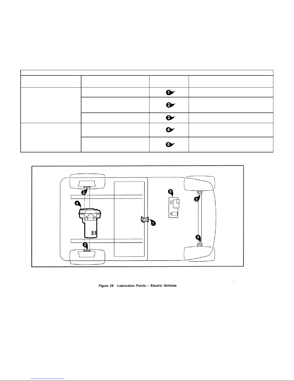
PERIODIC LUBRICATION SCHEDULE - ELECTRIC VEHICLES
REGULAR INTERVAL
SERVICE
LUBRICATION
POINTS
RECOMMENDED LUBRICANT
Semiannually by owner or
trained technician (every 50
hours of operation or 100
rounds of golf)
Charger receptacle
WD-40
Brake system, per maintenance and
service manual.
Dry Moly Lube, white lithium grease NLGI
#2
Front suspension (two fittings)
Chassis Lube - EP NLGI Grade 2
Annually by trained technician
only (every 100 hours of
operation or 200 rounds of
golf)
Check/fill transaxle to plug level
22 oz. (0.67 liters) SAE 30 WT. API Class SE,
SF, or SG Oil (or higher)
Pedal group
Dupont™ Performance Dry Multi-Use
Lubricant
PERIODIC LUBRICATION SCHEDULES
35
Page 37
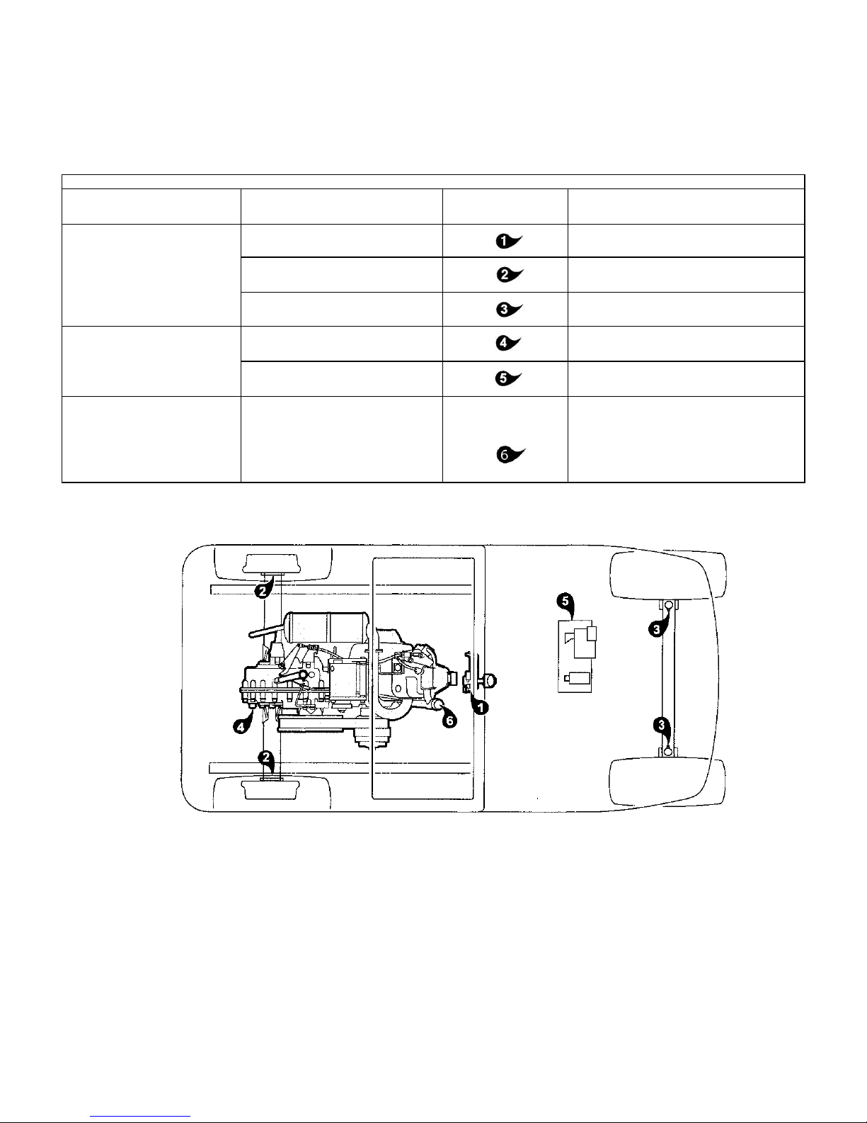
PERIODIC LUBRICATION SCHEDULE - GASOLINE VEHICLES
REGULAR INTERVAL
SERVICE
LUBRICATION
POINTS
RECOMMENDED LUBRICANT
Semiannually by owner or
trained technician (every 50
hours of operation or every 100
rounds of golf)
Shifter cable pivots
Dry Moly Lube (CCI P/N 1012151)
Brake system, per maintenance and
service manual.
Dry Moly Lube (CCI P/N 1012151), white
lithium grease NLGI #2
Front suspension (two fittings)
Chassis Lube - EP NLGI Grade 2
Annually by trained technician
only (every 100 hours of
operation or every 200 rounds
of golf)
Check/fill unitized transaxle to plug
level
27 oz. (0.8 liter) 80-90 WT. API Class GL-3 or
80-90 WT. AGMA Class EP Gear Lube
Pedal group
Dupont™ Performance Dry Multi-Use
Lubricant
First change 100 hours additional change every 200
hours of operation (or every 400
rounds of golf), or annually,
whichever comes first
Change engine oil and oil filter
(dispose of properly)
32 oz. (0.95 liter) without filter; 38 oz. (1.12
liters) with filter
36
Page 38

VEHICLE CONTROLLER - ELECTRIC VEHICLES
This electric vehicle is equipped with a solid state speed controller. In order to properly service and maintain the solid state
controller vehicle, it is necessary to understand the electrical circuitry and the functions of all components. Therefore, if any
repair or servicing needs to be performed, we recommend that it be performed by an authorized dealer.
BATTERIES - ELECTRIC VEHICLES
See General Warnings on page 7.
DANGER
• Battery - Explosive gases! Do not smoke. Keep sparks and flames away from the vehicle and service area.
Ventilate when charging or operating vehicle in an enclosed area. Wear a full face shield and rubber gloves
when working on or near batteries.
• Charge batteries in a well-ventilated area only. Batteries emit hydrogen while being charged. Hydrogen is
an explosive gas and must never exceed a level of 2% of the air.
• Battery - Poison! Contains acid! Causes severe burns. Avoid contact with skin, eyes, or clothing.
Antidotes:
- External: Flush with water. Call a physician immediately.
- Internal: Drink large quantities of milk or water followed with milk of magnesia or vegetable oil. Call a
physician immediately.
- Eyes: Flush with water for 15 minutes. Call a physician immediately.
WARNING
• Wear safety glasses or approved eye protection when servicing the vehicle or battery charger. Wear a full
face shield and rubber gloves when working on or near batteries.
• Use insulated tools when working near batteries or electrical connections. Use extreme caution to avoid
shorting of components or wiring.
CAUTION
• On all vehicles, turn off all accessories before charging batteries.
NOTE: Recycle or dispose of discarded batteries in accordance with local, state, and federal regulations.
Electric vehicles use deep-cycle batteries. Automotive batteries should never be used in electric vehicles.
New batteries will not deliver their full capabilities until they have been discharged and recharged 20 to 50 times. To obtain
the maximum service life from new batteries, restrict electric vehicles with new batteries to 36 holes of use between charges
in the first two months of operation. Batteries should be fully charged before first use of new vehicle, before first use of a
vehicle after storage, and before releasing vehicle for use each day.
BATTERY CARE - VEHICLES EQUIPPED WITH THE SINGLE-POINT WATERING SYSTEM
To keep batteries in good working condition, follow this maintenance program on a regular basis:
37
Page 39

1. Keep the batteries clean and free of corrosion. Wash tops and terminals of batteries with a solution of baking soda and
water (1 cup (237 mL) baking soda per gallon (3.8 L) of water). Rinse solution off of the batteries. Do not allow this
solution to enter the battery. Be sure terminals are tight. Let the terminals dry and then coat with Battery Terminal
Protector Spray.
NOTE: Please Dispose of waste water properly.
2. The battery hold-downs should be tight enough so that the batteries do not move while the vehicle is in motion, but not
so tight as to crack or buckle the battery case. For vecicles with a Style A battery configuration (Figure 2, Page 9),
tighten hold-down retaining nuts to 40 in-lb (4.5 N-m). For vehicles with a Style B or Style C battery configuration,
(Figure 3, Page 9) or (Figure 4, Page 10), tighten hold-down retaining nuts to 72 in-lb (8.1 N-m). The terminal
connections should be clean and tight, and any worn insulation or frayed wires should be replaced. Tighten battery
terminals to 110 in-lb (12.4 N-m). See following WARNING.
WARNING
• If battery wire terminals are damaged or corroded, replace or clean them as necessary. Failure to do so
may cause them to overheat during operation and could result in fire, property damage, or personal injury.
3. After use, charge the batteries. The batteries should never be left discharged any longer than absolutely necessary (do
not leave discharged overnight).
4. Water the batteries monthly or according to the watering interval. See Establishing the Watering Interval for New
Vehicles below. See Watering Batteries with the SPWS on page 43.
CAUTION
• The watering interval must adequately maintain the electrolyte level above the top of the plates. See Figure
30.
• Water the batteries only AFTER charging.
Establishing the Watering Interval for New Vehicles
If you do not already have a battery watering interval for your vehicles, manually check the battery water level weekly to
establish the correct watering interval. Thereafter, water batteries according to the established interval. During periods of
heavy use, add additional watering as required.
Single-Point Watering System Maintenance
1. For vehicles newly equipped with the Single-Point Watering System, the initial electrolyte level check on all battery cells
verifies that all the valves in the SPWS are functioning correctly. See Periodic Service Schedules on page 31. If a
valve fails to open, the cell will eventually dry out. The initial one-time inspection of all cells will identify any occurrence
of a valve that fails to open. If a valve fails to close, it will become evident due to the cell overflowing during routine
watering. Either failure scenario is rare, but should be monitored in the initial inspection and during routine watering
sessions. Replace malfunctioning valves to ensure maximum battery life. See following CAUTION.
CAUTION
• After checking the electrolyte, fully tighten the battery caps to prevent electrolyte leakage.
After the initial six-week inspection, manually check the electrolyte level at least once per year, particularly after long-term
storage or any other period of vehicle inactivity See preceding CAUTION.
38
Page 40
BATTERY CARE - VEHICLES WITHOUT THE SINGLE-POINT WATERING SYSTEM
To keep batteries in good working condition, follow this maintenance program on a regular basis:
1. Keep the batteries clean and free of corrosion. Wash tops and terminals of batteries with a solution of baking soda and
water (1 cup (237 mL) baking soda per gallon (3.8 L) of water). Rinse solution off of the batteries. Do not allow this
solution to enter the battery. Be sure terminals are tight. Let the terminals dry and then coat with Battery Terminal
Protector Spray.
NOTE: Please Dispose of Waste Water Properly.
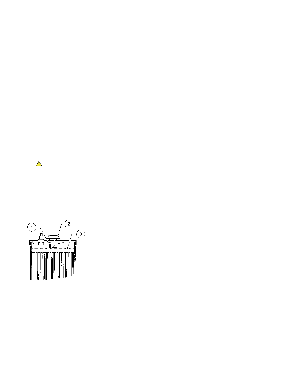
2. Check the electrolyte level weekly (Figure 30). Add water only after charging unless the electrolyte level is below the
top of the plates. In this case, add just enough water to cover the plates, charge, and then check the level again. Never
charge batteries if plates are exposed above electrolyte level. For best battery life, add only distilled water. See
following CAUTION and NOTE.
NOTE: A battery watering gun or bottle is available at many auto parts dealers.
3. The battery hold-downs should be tight enough so that the batteries do not move while the vehicle is in motion, but not
so tight as to crack or buckle the battery case. For vehicles with a Style A battery configuration(Figure 2, Page 9),
tighten hold-down retaining nuts to 40 in-lb (4.5 N-m). For vehicles with a Style B or Style C battery configuration
(Figure 3, Page 9) or (Figure 4, Page 10), tighten hold-down retaining nuts to 72 in-lb (8.1 N-m). The terminal
connections should be clean and tight, and any worn insulation or frayed wires should be replaced. Tighten battery
terminals to 110 in-lb (12.4 N-m). See following WARNING.
WARNING
4. After use, charge the batteries. The batteries should never be left discharged any longer than absolutely
necessary (do not leave discharged overnight).
• If battery wire terminals are damaged or corroded, replace or clean them as necessary. Failure to do so
may cause them to overheat during operation and could result in fire, property damage, or personal injury.
1. Level Indicator 2. Cap 3. Plates
Electrolyte level at least 1/2 inch (13 MM) above plates
or to level indicator.
Figure 30 Battery Electrolyte Level
39
Page 41

BATTERY CHARGER - ELECTRIC VEHICLES
DANGER
• The charging area must be ventilated. Hydrogen level in the air must never exceed 2%. The total volume of
air in the charging area must be changed five times per hour. Exhaust fans should be located at the highest
point of the roof. Contact a local HVAC engineer.
• Do not charge the vehicle batteries with the vehicle covered or enclosed. Any enclosure or cover should be
removed or unzipped and pulled back when batteries are being charged. An accumulation of hydrogen gas
could result in an explosion.
WARNING
Only trained technicians should repair or service the charger.
Each charger should have its own dedicated 15 or 20 ampere separately protected (circuit breaker or fuse)
single phase branch circuit, in accordance with all applicable electrical codes for the location.
Connect the charger AC supply cord to a properly grounded, three-wire outlet of the proper voltage and
frequency as shown on the charger.
Do not use an adapter to plug the charger with a three-prong plug into a two-prong outlet. Improper
connection of the equipment-grounding conductor can result in a fire or an electrical shock.
An extension cord or electrical outlet must accept a three-prong plug. Extension cord should be a three-
wire No. 12 AWG (American Wire Gauge) or no. 14 (British Standard Wire Gauge), and be as short as
possible. The use of improper extension cord could result in fire or an electrical shock.
Do not operate the charger if it has received a sharp blow, was dropped, or otherwise damaged in any way.
Have worn, cut, or damaged power cords or wires replaced immediately.
Do not use near fuels, grain dust, solvents, thinners, or other flammables. Chargers can ignite flammable
materials and vapors.
Do not expose to rain or any liquid. Keep the charger dry.
Never push objects of any kind into the charger through cabinet slots. They may touch dangerous voltage
points or cause an electrical short circuit that could result in fire or electrical shock.
Do not connect a stationary charger to the receptacle if the charger cord, plug, or the vehicle receptacle is
broken, damaged, or does not make a good electrical connection. Fire or personal injury can result. Have a
qualified technician replace the parts.
When the charger is on, the charger DC cord may be disconnected from the vehicle receptacle slowly.
Jerking or pulling the DC cord out quickly could cause arcing and burning that could damage the plug and
receptacle and could cause batteries to explode.
Do not block or cover the charger ventilation slots. The slots provide ventilation and protect the charger
from overheating.
Do not allow clothing, blankets, or other material to cover the charger.
Do not allow the charger to operate for more than 30 minutes at 19 or more amperes.
Install surge arrestors on incoming AC power lines. Surge arrestors will help protect electrical components
in the charger and on the vehicle from all but direct or close lightning strikes.
40
Page 42

NOTE: Because the vehicle's onboard computer (OBC) (if so equipped) has a storage charge feature that
automatically checks and recharges the batteries as necessary every 15 days, the charger can remain
plugged to the vehicle throughout the storage period.
At one hour and at two hours into the charge cycle, the charger will shut off in order to run a self-diagnostic program
(ammeter will drop to zero). Charging will resume in a few moments (ammeter returns to previous rate of charge).
Each electric vehicle is supplied with a fully automatic battery charger as standard equipment. The AC cord to each charger
is to be connected to a source capable of supplying 15 amperes minimum per charger.
To reduce the risk of electric shock, the battery charger must be grounded. The charger is equipped with an AC electric cord
having an equipment-grounding conductor and a grounding type plug. The AC plug must be connected to an appropriate
receptacle that is properly installed and grounded in accordance with the National Electrical Code and all local codes and
ordinances. See the owner's manual supplied with the charger for specific operating instructions before using the charger.
The use of an extension cord with the charger should be avoided. If an extension cord must be used, use a three-conductor
no. 12 AWG (American Wire Gauge) or no. 14 SWG (British Standard Wire Gauge), heavy-duty cord with ground, properly
wired and in good electrical condition. Keep it as short as possible (no more than 12 feet (3.7 m)). Place all cords so they will
not be stepped on, tripped over, or otherwise subject to damage or stress.
Ensure that the charger ventilation slots are unobstructed and that there is adequate ventilation.
CHARGING BATTERIES
WARNING
• Be sure all wire connections at the receptacle and the fuse link are clean and tight.
• Do not rock or bend the plug. To connect the charger plug to the vehicle receptacle, grasp the plug handle
and push the plug straight into the receptacle (Figure 31, Page 42).
• Do not pull on the DC cord (Figure 32, Page 42). Do not twist, rock or bend the plug. To disconnect the
charger plug from the vehicle receptacle, grasp the plug by the handle and pull the plug straight out of the
receptacle.
• Do not connect a charger to the receptacle if the charger cord, plug, or the vehicle receptacle is broken,
damaged in any manner, or does not make a good electrical connection. Fire or personal injury can result.
Have it replaced by a qualified service person immediately.
• Failure to follow these instructions could result in damage to the charger cord, the plug, and (or) the
vehicle receptacle.
• Do not use a charger if:
- The plug is too loose or does not make a good connection.
- The plug and receptacle feel hotter than normal during charge.
- The plug pins or receptacle contacts are bent or corroded.
- The plug, receptacle, or cords are cut, worn, have any exposed wires or are damaged in any way.
• Using the charger with any of the above symptoms could result in a fire, property damage, personal injury,
or death.
41
Page 43
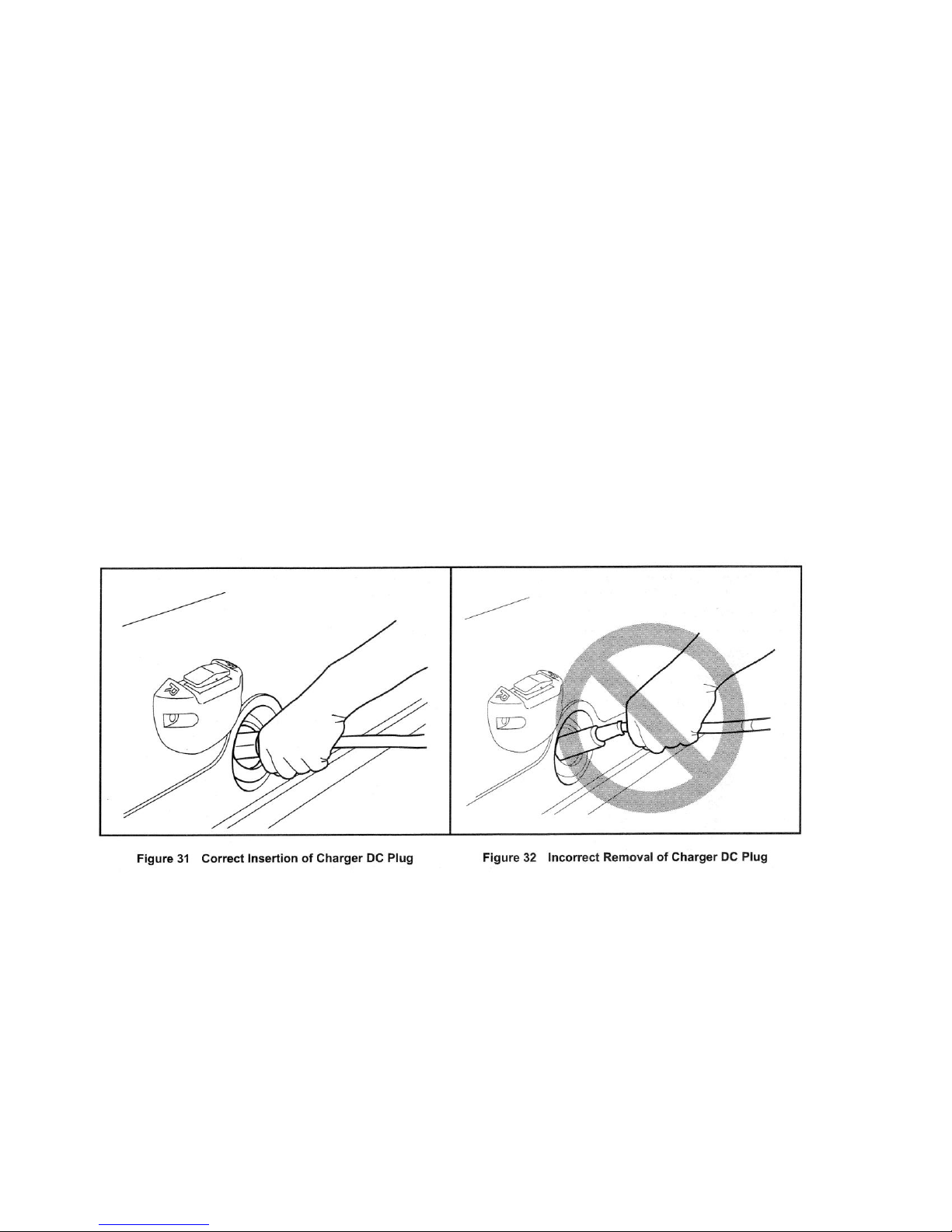
NOTE: When temperatures fall below 65 °F (18.3 °C), batteries charged in unheated areas should be placed on charge as
soon as possible after use. Batteries are warmest immediately after use, and cold batteries require more time to
fully charge.
Insert the charger DC plug into the vehicle receptacle. The charger will turn on two to ten seconds later (Figure 31, Page
42).
When inserting the DC plug, align the raised guide on the plug with the guide slot in the receptacle and push straight in
slowly.
Cruise Car battery chargers interact with the vehicle onboard computer, if the vehicle is so equipped. The computer records
the amount of energy consumed during vehicle use. While the charger is plugged in, the vehicle's control circuit is locked
out, preventing operation of the vehicle, as well as the possibility of consequent damage to the charger and the vehicle.
Once the lockout is actuated, the charger turns on. The onboard computer then records the amount of energy being returned
to the batteries. When the optimum amount of energy needed to replenish the batteries is returned, the charger will shut off.
The control circuit lockout remains activated until the charger plug is disconnected from the vehicle.
Only PowerDrive battery chargers are compatible with electric vehicle models equipped with an onboard computer.
As long as the charger is allowed to shut off by itself, the batteries will be fully charged. Overcharging and
undercharging will normally be prevented.
Batteries should be put on charge even if they have been used for only a short period (9 holes of golf or 10 minutes). The
charger is automatic and will turn off when batteries are fully charged. If the charger does not seem to be operating properly,
or if the batteries seem weak, contact your local distributor/dealer.
PLUG AND RECEPTACLE
The charger cord, plug, and receptacle are wear items and should be inspected daily. Visually inspect them for cracks, loose
connections, and frayed wiring; they must be replaced when worn or damaged. If charger plug or receptacle show signs of
corrosion or the plug is difficult to insert or remove, the receptacle contacts and plug terminals should be cleaned with a good
electrical contact cleaner or lightly sprayed with WD-40® brand spray lubricant. The plug should then be inserted and
removed several times to ensure ease of insertion, ease of removal, and good electrical contact. See following NOTE.
NOTE: If the warning tag has been damaged or removed from the DC cord, have it replaced immediately.
42
Page 44
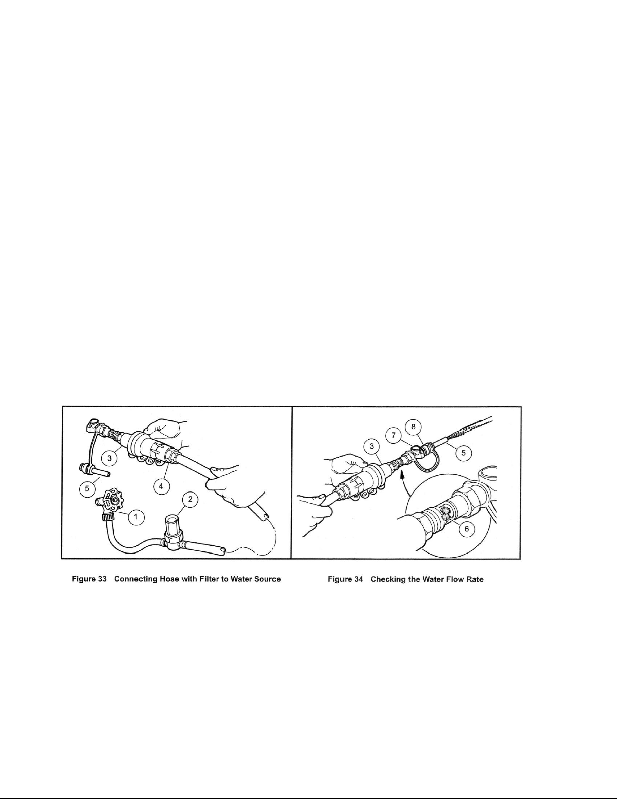
SINGLE POINT WATERING SYSTEM (SPWS)
CAUTION
• Water the batteries only AFTER charging.
• Use only the equipment provided in the Cruise Car SPWS Refill Kit (CCI P/N 102958001) to water batteries
with the SPWS.
WATERING BATTERIES WITH THE SPWS
Checking the Water Flow Rate
1. Connect the water hose with the built-in screen filter (2) to the water faucet (1) (Figure 33). See following CAUTION.
CAUTION
• Make sure the screen filter is clean.
• Do not use a longer garden hose than provided with the System (20 feet), as a decrease in water pressure could
overfill the batteries and damage the refill system.
2. Before screwing the hose-end assembly (3) onto the opposite end of the water hose, check the screen filter (4) inside the
end of the assembly to make sure it is clean (Figure 33).
3. Connect the purger (5) to the female coupler (8) on the hose-end assembly (Figure 34).
4. Completely open the water faucet until the water flows out of the hose-end assembly (3), and note the movement of the
red flow indicator balls (6). See following NOTE
NOTE: The water flow rate must be at least two gallons-per-minute for the SPWS to function properly This step also
eliminates any trapped air from the water hose.
5. After ensuring adequate water flow rate, press the grey button (7) on the end of the female coupler (8) to disconnect
the purger from the pressure regulator.
Refilling the Batteries
43
Page 45
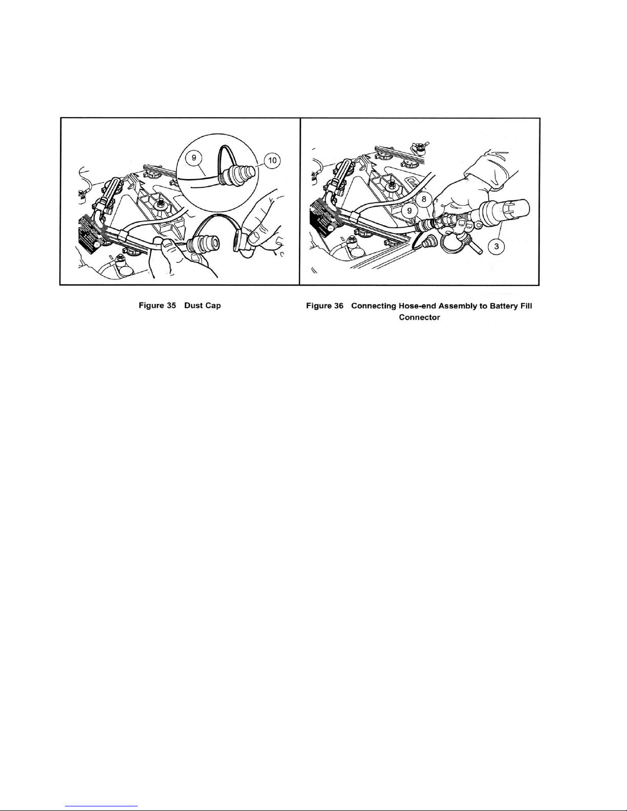
1. Locate the battery fill coupling (9) on the driver side of the battery compartment, remove the dust cover (10) from
the male connector (Figure 35), and connect the hose-end assembly (3) (Figure 36). The water flow will begin
immediately
2. The red flow indicator balls should swirl, indicating that the batteries are being filled. See following CAUTION.
CAUTION
• If at any time water overflows from the batteries, immediately stop the refill process, disconnect the
pressure regulator from the battery fill coupling, and call for service.
3. When the red flow indicator balls stop moving, immediately press the grey button to disconnect the hose-end
assembly from the battery fill coupling (9), and squeeze the dust cover (10) to lightly secure it to the male connector
of the battery fill coupling (Figure 35).
4. Place the battery fill coupling into the space between the battery bucket and the car body. Leaving the fill coupling
on top of the battery bank or tucked between the batteries and the battery bucket can result in coupling damage.
5. Turn the water faucet off when finished filling the vehicle(s).
44
Page 46

BATTERY - GASOLINE VEHICLES
See General Warnings on page 7.
DANGER
• Battery - Explosive gases! Do not smoke. Keep sparks and flames away from the vehicle and service area.
Ventilate when charging or operating vehicle in an enclosed area. Wear a full face shield and rubber gloves
when working on or near batteries.
• Tools, wires, and metal objects can cause sparks when shorted across a battery.
• Follow all instructions carefully when working with batteries.
• Charge battery in a well-ventilated area only.
• Battery - Poison! Contains acid! Causes severe burns. Avoid contact with skin, eyes, or clothing.
Antidotes:
- External: Flush with water. Call a physician immediately.
- Internal: Drink large quantities of milk or water followed with milk of magnesia or vegetable oil. Call a
physician immediately.
• Eyes: Flush with water for 15 minutes. Call a physician immediately.
WARNING
• Do not jump start a dead battery using another battery and jumper cables.
The battery in the gasoline vehicle is a 12-volt, low maintenance battery that requires infrequent watering (Figure 37).
Any corrosion around the positive (+) or negative (-) terminals should be washed off with a solution of baking soda and water
(1 cup (237 mL) per gallon (3.8 L) of water). Rinse solution off the battery. Do not allow this solution to enter battery. Be sure
terminals are tight (battery terminals should be tightened to 144 in-lb (16 N-m). Let the terminals dry and then spray them
with Battery Terminal Protector Spray. See preceding and following WARNINGS
45
Page 47
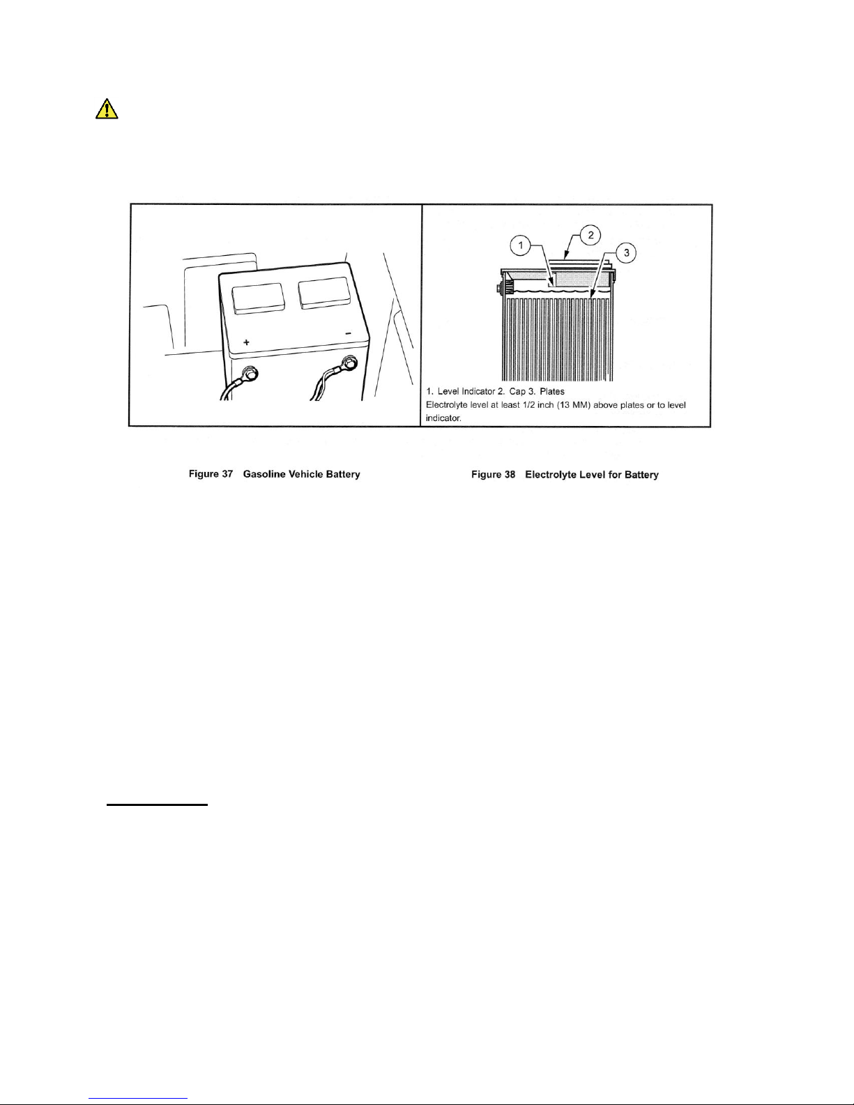
WARNING
• If battery wire terminals are damaged or corroded, replace or clean them as necessary. Failure to do so
may cause them to overheat during operation and could result in fire, property damage, or personal injury.
Be sure battery clamp is properly tightened. Tighten to 144 in-lb (16 N-m). A loose battery clamp may allow the battery to
become damaged from vibration or jarring.
If battery appears weak, have it charged by a trained technician. The battery should never be left discharged any longer than
absolutely necessary (do not leave discharged overnight).
ENGINE OIL - GASOLINE VEHICLES
ENGINE OIL LEVEL CHECK
1. Remove the oil level dipstick from the oil filler tube, and wipe oil off dipstick (1) (Figure 39). See following
CAUTION.
CAUTION
• Do not remove dipstick while engine is running.
2. Check oil by fully inserting the dipstick into the oil filler tube (2) and immediately removing it.
3. If the oil level is at or below the low level mark on the dipstick gauge, add oil until the level is between low and full
levels (safe level) (3).
4. Insert the dipstick into the oil filler tube.
NOTE: Properly recycle or dispose of used oil in accordance with environmental laws.
46
Page 48
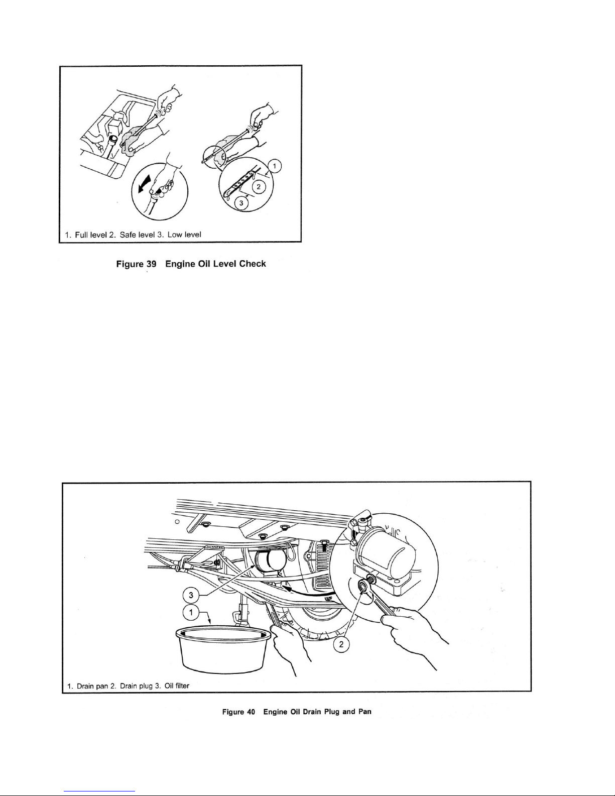
Even though the low oil warning light on the dash should warn you if your oil becomes low, engine oil level should be
checked monthly. Vehicle should be on a level surface when checking oil. Do not overfill with oil.
ENGINE OIL AND FILTER CHANGE
Engine oil and oil filter should be changed after the first 100 hours of operation. After that, they should be changed every
200 hours of operation or annually, whichever comes first.
1. Turn the key switch to the OFF position, then remove the key. Place the Forward/Reverse handle in the
NEUTRAL position. Chock the front wheels.
2. Access the engine compartment.
3. Disconnect the battery cables, negative (-) cable first. See WARNING "To avoid unintentionally starting..."
on page 8.
4. Position a pan designed for oil changes under the front drain plug (Figure 40).
47
Page 49
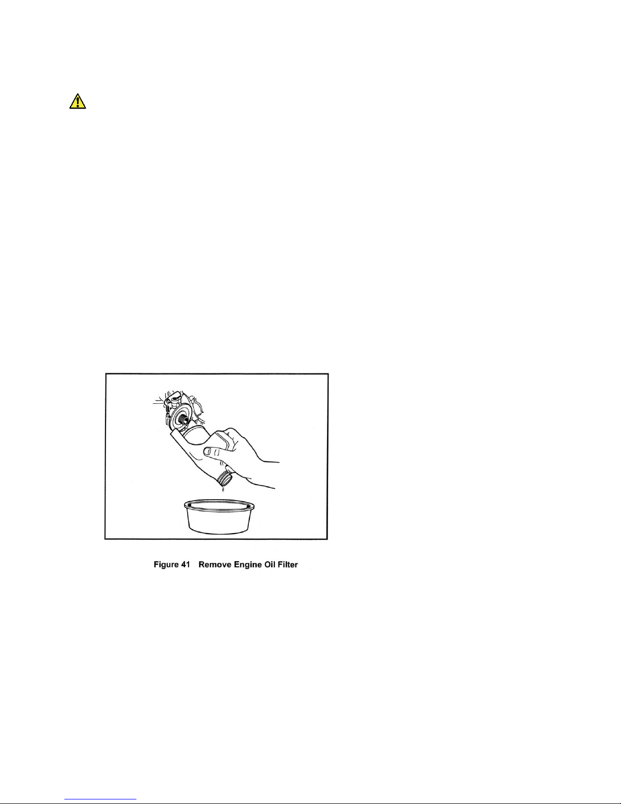
5. Use a 14 mm socket or wrench to remove the drain plug, turning it counterclockwise, and allow the engine
oil to drain into the pan. See following WARNING.
WARNING
Do not attempt to change engine oil when the engine is hot or even warm. Engine oil can cause skin burns
Wear safety glasses or approved eye protection when servicing the vehicle. Wear rubber gloves when
handling oil drain plug, oil filter, and oil drain pan.
6. Clean the oil drain plug threads with solvent to remove oil and oil residue. Make sure that the compression washer
remains on the drain plug.
7. Use a 14 mm socket or wrench and replace the front oil drain plug, turning it clockwise, and tighten to 18 ft-lb
(24.4 N-m).
8. Relocate the oil drain pan to a position under the engine oil filter (Figure 40).
9. Remove the engine oil filter, turning it counterclockwise, allowing the residual oil in the filter port and filter to drain into
the oil drain pan (Figure 41). See following NOTE.
NOTE: An oil drip guard can be used to prevent excess oil from dripping into the engine base plate. Use an empty quart
(one liter) container and cut the bottom off at an angle, then slide the open area of the container up and under the
oil filter prior to removing. Position the port of the plastic container so oil will be directed into the oil pan. Or, make a
drip guard by folding a piece of cardboard, thin metal, or plastic under the oil filter forming a channel to direct the
filter port oil into the drain pan.
Dispose of used oil according to the environmental laws and regulations for your area.
10. Use a clean rag and wipe the oil filter mounting bracket surface clean where the oil filter gasket seats.
11. Install a new oil filter onto the engine oil filter port. Apply a light coat of white lithium NLGI Number 2 grease (Dow
Corning® BR2-Plus or equivalent) or new engine oil to the rubber seal around the outside surface of the filter before
attaching it to the oil filter port (Figure 42). This will help seal the filter to the oil filter mounting bracket.
NOTE: Use only oil filters designed for this engine.
12. Tighten the oil filter by hand until tight. Do not use a band wrench or channel lock plier to tighten.
13. Remove the dipstick and add engine oil into the dipstick port. Use a funnel or pour spout to direct the oil into the dipstick
port. With filter change, the engine requires 38 ounces (1.12 liters) of oil per change. Refer to oil viscosity guidelines for
selection of oil grade (Figure 43). Replace the dipstick
48
Page 50
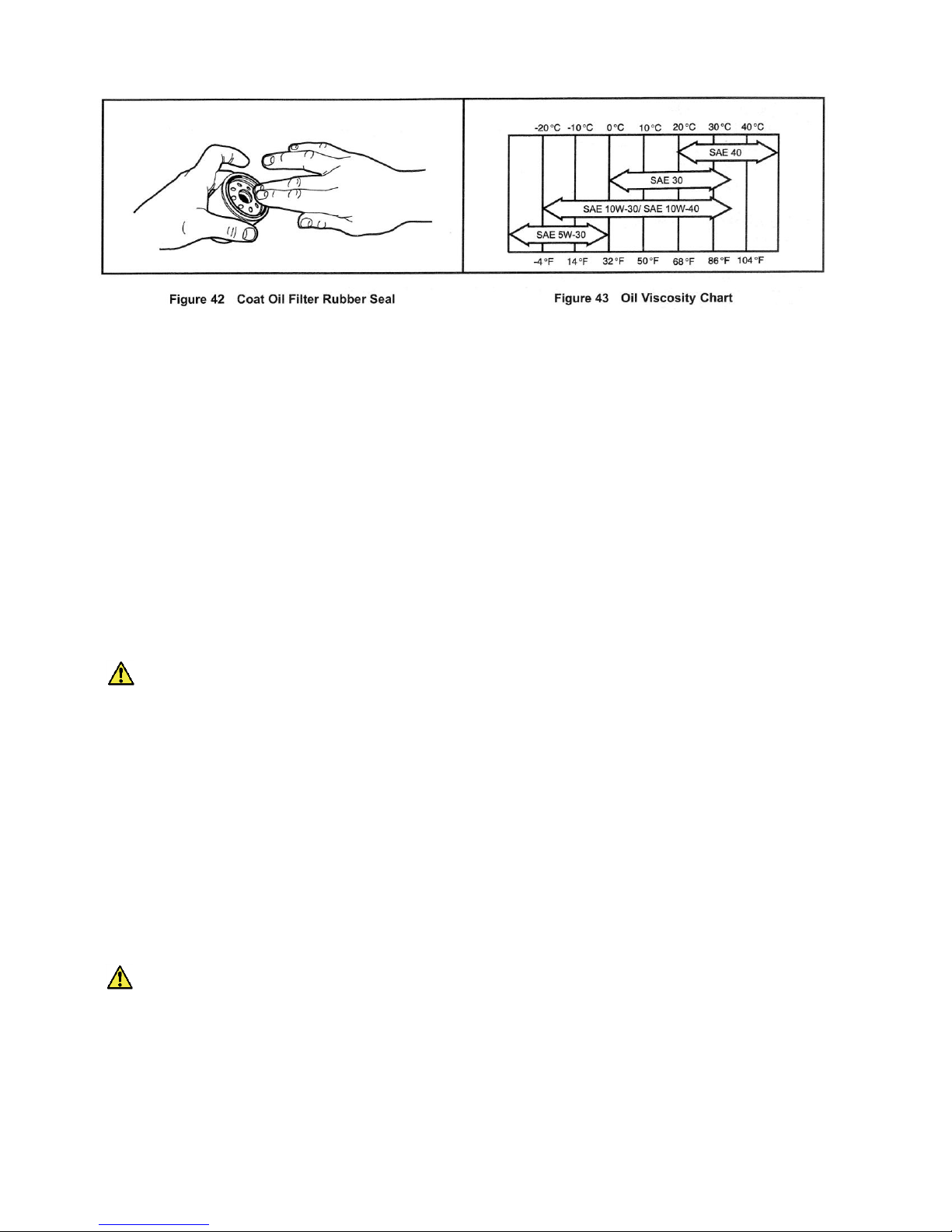
14. Connect the battery cables, positive (+) cable first, and tighten terminals to 144 in-lb (16 N-m). Coat terminals with
Battery Terminal Protector Spray.
15. With the Forward/Reverse handle in the NEUTRAL position, start and run the engine for a few minutes. Observe
both the drain plug and the oil filter from under the vehicle and watch for oil leaks. If leaks appear, begin with step 1
and repeat the appropriate step for either or both items to correct the problem.
16. Remove the dip stick and check the engine oil as a final step. Replace the dip stick.
FUELING INSTRUCTIONS - GASOLINE VEHICLES
See General Warnings on page 7.
DANGER
• Turn the key switch to the OFF position before fueling.
• Do not pour fuel into the fuel tank when the engine is hot or while it is running.
• Be sure the fuel tank ground wire, located next to the fuel shut-off valve, is properly connected before
fueling the vehicle.
• To avoid electric arc caused by static electricity, the fuel storage/pumping device must be grounded. If the
pump is not grounded, the vehicle must be grounded to the pump before and during the fueling operation.
• If the vehicle has an all-weather enclosure installed, be sure the fuel tank is properly vented as shown
(Figure 27, Page 29).
• To avoid the possibility of fire, clean up any spilled fuel before operating the vehicle.
CAUTION
• To allow for expansion, do not fill higher than 2.54 cm (one inch) from the top of the fuel tank. Avoid spilling
fuel.
NOTE: Whenever possible, avoid using oxygenated fuels and fuels that are blended with alcohol. Vehicles to be stored for
extended periods should be prepared for storage as instructed. See Preparing the Gasoline Vehicle for Extended
Storage on page 28.
49
Page 51

1. Turn the key switch to the OFF position.
2. Lift and remove seat bottom.
3. The fuel tank is located on driver side of vehicle. Remove fuel cap and fill the fuel tank with fresh unleaded gasoline
only. See preceding CAUTION.
4. Replace fuel cap on tank. Ensure that cap is tightened securely.
5. Replace seat bottom.
CLEANING THE VEHICLE
Cruise Car vehicles are equipped with hand-washable front and rear bodies. Use only commercially available automotive
cleaners with a sponge or soft cloth for normal cleaning. A garden hose at normal residential water pressure is adequate.
The manufacturer does not recommend any type of pressure washing or steam cleaning. Such a process will expose
electrical components to moisture. Moisture entering electrical components can result in water damage and subsequent
component failure.
Use non-abrasive wax products. Battery acid, fertilizers, tars, asphalt, creosote, paint, or chewing gum should be removed
immediately to prevent possible stains. See following CAUTION.
CAUTION
• Use of leveling or rubbing compounds will permanently dull finish of vehicle.
• Do not apply wax products to the black plastic material of the front and rear underbody, the front bumper,
or the textured area of the rear beauty panel marked "NO STEP." Wax will cause these surfaces to become
discolored.
The seats of the vehicle will last longer with proper cleaning. Use a solution of 10% liquid soap and warm water applied with
a soft cloth. For imbedded dirt, a soft bristle brush may be used.
Please dispose of waste water properly.
ACCESSORY ONBOARD CHARGER
An onboard charger, which is installed under the rear seat, is available for the electric vehicle. The charger should be
plugged into a properly grounded outlet. The AC line to which the charger is to be connected must be of the proper AC input
voltage for the charger and must be capable of supplying sufficient current. See the battery charger owner's manual supplied
with the battery charger for specific operating instructions and specifications before using the charger. See following
WARNING and CAUTION.
WARNING
Each charger should have its own dedicated 15 or 20 ampere separately protected (circuit breaker or
fuse) single phase branch circuit, in accordance with all applicable electrical codes for the location.
CAUTION
• Before charging batteries, turn off all accessories on all vehicles.
• If using an onboard charger, be sure the AC plug is unplugged from the outlet before attempting to drive
the vehicle.
50
Page 52

• Be sure the AC cord is properly wound up on the reel before driving the vehicle.
• Study all general information and WARNING, CAUTION, and NOTE statements in the Battery Charger
section on page 40-41.
NOTE: If the vehicle is constantly hauling heavy loads, the preventive maintenance procedures should be
performed more often than recommended in the service and lubrication schedules.
51
Page 53
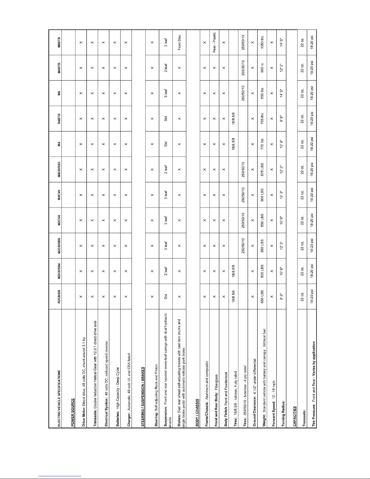
52
Page 54
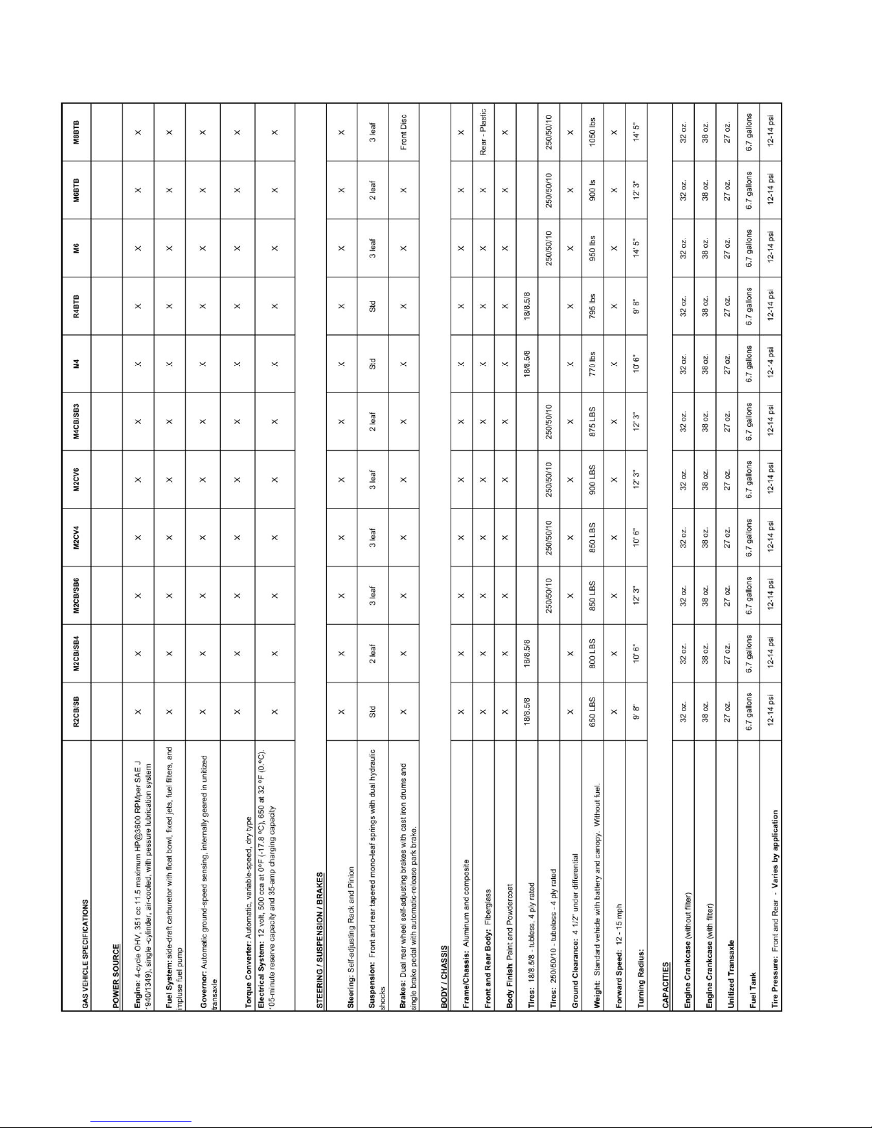
53
Page 55

Corrosion Prevention
Airborne salt (coastal environments) should be rinsed off of the vehicle daily to avoid
long term corrosion issues.
Bi-weekly spray wax is recommend for non aluminum parts such as seat belt
buckles and accessory nuts & bolts, etc.
Bi-weekly WD-40 lubricant (or equivalent) should be applied to moving parts,
including rack & pinion steering, shocks, etc.
Bi-weekly check battery water levels. Top off with clean distilled water.
Regularly check battery terminal connections to make sure all are secured and
lubricated. Loose connections can cause dangerous sparking.
Regularly check for loose nuts, bolts and brackets and tighten as needed.
Solar Top Maintenance (if vehicle is so equipped)
The solar is designed to be simple to maintain as it has no moving parts. However, it should
be kept clean with a mild window detergent. The panel serves as a trickle charger for the
batteries and works to keep the batteries topped off. The charge controller senses when the
batteries are completely charged and will automatically close the circuit to prevent
overcharging. The solar charging system does not always update the battery level indicator,
so it is recommend to briefly plug in the wall charger for the meter to reset to the proper level.
The battery manufacturer suggests plugging the vehicle to the wall unit as least once a month
to properly calibrate the batteries.
SUBSEQUENT OWNER REGISTRATION
In the event a vehicle is bought as a used vehicle, we strongly urge the new owner to register
the vehicle with Cruise Car, Inc. This will enable us to contact you if the need arises. Please
send your name, address, and serial number(s) of the vehicle(s) to: Cruise Car, Inc. 5120
Middle Ave, Suite 5, Sarasota FL 34234.
54
 Loading...