

Cruisair Zephyr, Cuddy dc Installation And Operation Manual
Zephyr (ZF) & Cuddy dc
❖
INSTALLATION • OPERATION
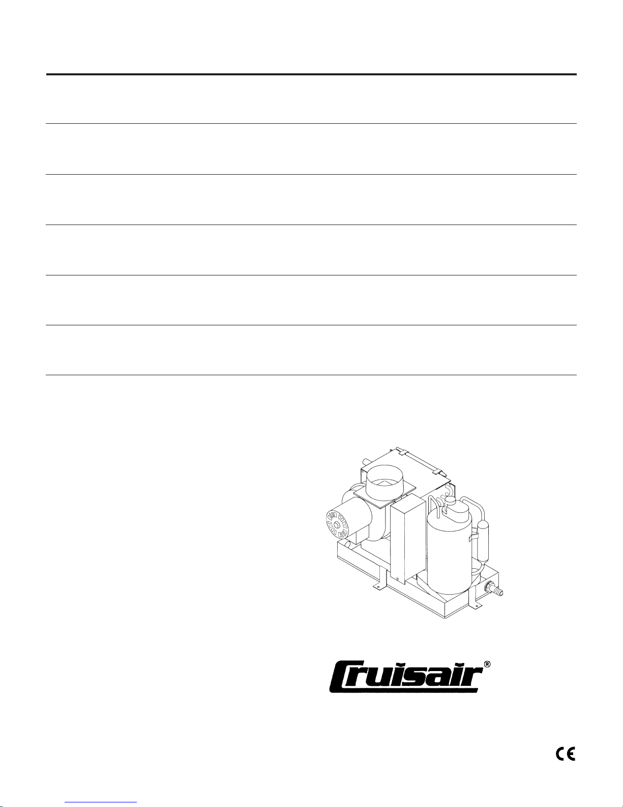
Zephyr & Cuddy dc Self-Contained
Cooling Only A/C Kits
Revised: 5-11-07
L-2028


Table of Contents
Zephyr and Cuddy dc Units • Installation
Warning .............................................................................. 4
Notice ................................................................................. 4
Introduction ......................................................................... 4
Cuddy dc ............................................................................ 4
Unpacking and Inspection .................................................. 4
Safety Considerations ........................................................ 4
Placement Of System ......................................................... 5
Spacing Allowances & Unit Dimensions ............................. 5
How It Works ...................................................................... 6
Mounting Brackets .............................................................. 6
Condensate Drains ............................................................. 6
Blower Assembly ................................................................ 6
Supply & Return Air Grills
and Transition Boxes ........................................................ 6
Ducting ............................................................................... 7
Manual Control Panel Installation ....................................... 7
Electrical Connections, Grounding & Bonding for AC
Powered Zephyr ............................................................... 7
Electrical Connections, Grounding & Bonding for DC
Powered Cuddy dc .......................................................... 7
Electrical System and Wiring for DC Powered Cuddy dc .... 8
Notice and ABYC Standards: ............................................. 8
Seawater Pump and Plumbing ........................................... 8
Installation Checklist
(review prior to and after installation) ............................... 9
Zephyr and Cuddy dc Units • Operation
Operation .......................................................................... 10
Troubleshooting Guidelines .............................................. 10
Zephyr and Cuddy dc Units • Maintenance
Seawater Strainer ............................................................. 12
Condenser Coil Cleaning ................................................. 12
Return Air Filters............................................................... 12
Winterization ..................................................................... 12
Zephyr and Cuddy dc Kits • Parts List 12
Owner’s Limited Warranty 15
Limited Warranty Periods 17
Descriptions of Figures 18
Cruisair Worldwide Service Dealer Locator 27
L-2028
3
❖
English

Zephyr and Cuddy dc Units • Installation
Warning
This manual contains essential safety information concerning
the safe and proper installation and operation of Zephyr and
Cuddy dc self-contained direct expansion air conditioners. It is
very important that you read and understand the contents of
this manual thoroughly before attempting to install any
Cruisair equipment. If there are any statements in this manual
that you do not understand, contact the Dometic Environmental Applications Department (Dometic) for assistance. Phone
(804) 746-1313, Fax (804) 746-7248 (8:00am - 5:00pm
United States Eastern Time).
Notice
As of July 1, 1992, United States federal law prohibits the
intentional release of refrigerant gases into the environment,
including the R-22 refrigerant mostly used in Cruisair air
conditioning systems. Special care must be taken when
installing, charging and servicing Cruisair equipment to
prevent any loss of refrigerant.
Cruisair does
to purge air and moisture from the system at installation. This
formerly used practice of purging is in violation of United
States federal law.
not recommend the practice of using refrigerant
Introduction
You have just purchased the first complete built-in marine air
conditioning system designed for self installation. We are
confident you will find the added comforts experienced in your
boat to be well worth the money spent. If, upon opening your
new system, you discover any parts are missing, contact your
dealer immediately.
Before attempting to install your new Zephyr (AC powered) or
Cuddy dc (DC powered) air conditioning system, you must
read this installation manual completely. Failure to perform
certain tasks in the proper sequence could result in an
inoperative system as well as a voided warranty.
Cuddy dc
The new Cuddy dc marine air conditioner is very similar to
the standard Zephyr but is unique in one way–it is designed to
be run on 12VDC battery power. Most of the installation,
operation and maintenance information in this manual applies
to both types of air conditioners, the AC voltage Zephyr and
the DC voltage Cuddy dc. Installation of either unit is nearly
identical with the exception of the power supply and how that
power is connected to the unit, control and pump. With that in
mind while reading this manual, please read the Installation,
Operation, and Maintenance sections titled “Zephyr and
Cuddy dc Units”, and especially the sections subtitled “for DC
Powered Cuddy dc”. Cuddy dc owners may skip the sections
that are subtitled “for AC Powered Zephyr.”
Cuddy dc kits contain the air conditioning unit and these
three components: a Dedicated Power Module (DPM), a 2knob mechanical control, and the water pump. Each of these
components is connected to the a/c unit with a polarized plug.
These plugs are configured unique to each component. The
DPM is sized to run the Cuddy dc system only and should not
be used for any other appliance(s). See Figure 14 in the back
of this manual for DPM specifications
! WARNING The DPM is not ignition protected and must not
be installed in the engine compartment or in any area with
flammable or compressed gasses or liquids (see the Safety
Considerations section of this manual for more information).
Dometic recommends using a separate battery bank dedicated to run the Cuddy dc. For specific instructions, please
see the two sections in this manual titled “Electrical System
and Wiring for DC Powered Cuddy dc” and “Electrical Connections, Grounding & Bonding for DC Powered Cuddy dc.”
! WARNING The compressor and fan on the Cuddy dc air
conditioning unit are AC voltage components, running on
115VAC supplied by the DPM. The pump and 2-knob
mechanical control also run on 115VAC supplied by the DPM.
Once the DPM is connected to the dedicated 12VDC battery
bank, then all necessary power distribution to each of the
components is handled through the polarized plugs—truly a
“plug & play” system.
Unpacking and Inspection
When the equipment is received, all items should be carefully
checked against the packing list to ensure all cartons have
been received. Move units in the normal “up” orientation as
indicated by the arrows on each carton. Examine cartons for
shipping damage, removing the units from the cartons if
necessary. If the unit is damaged, the carrier should make the
proper notation on the delivery receipt acknowledging the
damage.
CAUTION: When unpacking and installing the control, care
must be taken not to kink or break the copper cap tube when
uncoiling the sensing bulb. The cap tube is hollow and kinking
or sharp bends will inhibit system operation.
Safety Considerations
Never install your air conditioner in the bilge or engine room
areas. Insure that the selected location is sealed from direct
access to bilge and/or engine room vapors. Do not terminate
condensate drain line within three (3) feet of any outlet of
engine or generator exhaust systems, nor in a compartment
L-2028 Installation
4
❖
English

housing an engine or generator, nor in a bilge, unless the
drain is connected properly to a sealed condensate or shower
sump pump. Failure to comply may allow bilge or engine room
vapors to mix with the air conditioners return air and contaminate living areas which may result in injury or death.
Consideration should be given to installing a trap in the
condensate drain line(s) so that normal discharge of condensate can fill the trap and prevent the ingress of carbon
monoxide (CO) or other potentially harmful vapors.
Installation and servicing of this system can be hazardous
due to system pressure and electrical components. When
working on this equipment, always observe precautions
described in the literature, tags and labels attached to the unit.
Follow all safety codes. Wear safety glasses and work gloves
and place a fire extinguisher close to the work area. The
following is a summary of the labels on the unit:
! DANGER Electrical shock hazard. Disconnect voltage at
main panel or power source before opening any cover. Failure
to comply may result in injury or death.
! WARNING This component does not meet Federal requirements for ignition protection. Do not install in spaces containing gasoline engines, tanks, LPG/CPG cylinders, regulators,
valves or fuel line fittings. Failure to comply may result in injury
or death.
NOTICE This component is charged with hydrochlorofluorocarbon (HCFC) refrigerant R22. Effective July 1, 1992 it shall
be unlawful for any person to knowingly vent or otherwise
knowingly release any class 1 (CFC) or class 2 (HCFC)
substance as a refrigerant in a manner which permits such
substance to enter the atmosphere per the clean air act of
1990. Public law 101-549 Title IV Section 608-c. Failure to
comply may result in severe penalties, including fines and
imprisonment. Note: The Cuddy dc unit is charged with
R417A.
! WARNING To minimize the hazard of electrical shock and
personal injury, this component must be effectively grounded.
Refer to the installation guidelines for further information.
! WARNING The compressor and fan on the Cuddy dc air
conditioning unit are AC voltage components, running on
115VAC supplied by the DPM. The pump and 2-knob
mechanical control also run on 115VAC supplied by the DPM.
Disconnect voltage at main panel or power source before
opening any cover. Failure to comply may result in injury or
death.
Placement Of System
Selecting a good location for your air conditioner is the most
important part of your preparations. Be sure to consider the
size of the area you are cooling, the air distribution needs,
and the size of the unit you have chosen. Keeping in mind that
cool air has a tendency to fall, it is highly recommended that
L-2028 Installation
you locate the supply air grill as high as possible in the cabin.
Figure 1a at the back of this manual shows the single duct
application and Figure 1b shows a dual duct application.
The air conditioning unit should be installed as low as
possible, but never in the bilge or engine room areas.
Insure that the selected location is sealed from direct
access to bilge and/or engine room vapors. Installing the
unit as low as possible (such as under a V-berth, dinette seat
or bottom of a locker) and ducting the supply air as high as
possible, creates an ideal air flow condition. This type of
installation will prevent short or premature cycling.
The unit should be positioned on a firm, level, horizontal
surface and the condensate drain line should run downward
from the unit to a suitable drain location. Plan all connections
which must be made including ducting, condensate drain,
seawater in and out, electrical power connections, location of
control, and seawater pump placement, to assure easy
access for routing and servicing.
Tools Required for Installation
• Screw drivers
• Pliers
• Pipe wrench
• Wire cutters/crimpers
• Drill & 7/8" bit
• Jig saw
• Duct tape
• Electrical tape
• Teflon tape
• Bedding compound to seal thru hull fittings
• Hardware to secure unit, pump, strainer, grills & control
panel
Spacing Allowances & Unit Dimensions
The following space allowances should be considered when
mounting the unit:
1. Allow a minimum of 6" (152mm) around the perimeter of
the unit in the area of the seawater and condensate drain
piping.
2. Allow a minimum of 3" (76mm) of air space in front of the
evaporator coil for the return air intake if it is adjacent to a
bulkhead.
3. Allow a minimum of 3" (76mm) of air space for the electric
blower motor ventilation. For Cuddy dc systems, allow at
least 1" (25mm) above DPM for adequate ventilation.
4. For flexible ducting connection, allow 2" (51mm) for the
duct ring, 1" (25mm) for the duct bend radius and add
diameter of the ducting to get the total clearance distance
(2" [51mm] + 1" [25mm] + duct diameter) as measured
from the blower outlet (this also applies to clearance
needed behind the supply air grill). Note that the blower
and duct ring can be positioned either vertically or
horizontally. See Figure 2 at the back of this manual.
5
❖
English

These space allowances are suggested minimums. Enough
space should be allocated for installation and serviceability.
See Figure 2 at the back of this manual for space allowances
and unit dimensions.
How It Works
The air conditioning unit consists of four main components
and a refrigerant gas circulating through the system. The
BLOWER draws warm cabin air across the fins on the
EVAPORATOR where the heat from the air is transferred to
the refrigerant in the evaporator coil. As the refrigerant
evaporates from a liquid into a gas it absorbs the heat from
the cabin air. The COMPRESSOR then compresses the
refrigerant gas and pumps it through the outer tube in the
CONDENSER COIL. The seawater pump circulates cool
seawater through the inner tube in the condenser coil, this
cools the refrigerant in the outer tube and condenses it from a
gas into a liquid. The heat from the refrigerant is exchanged to
the seawater and discharged overboard. The liquid refrigerant
is then passed through the EVAPORATOR COIL and the
cycle repeats. Removing heat from the cabin air lowers its
temperature. The cooled air is blown through the ducting and
out the supply air grill(s). See Figure 3 at the back of this
manual for component identification.
Mounting Brackets
The air conditioning unit is supplied with a base pan that also
serves as a condensate pan. Mounting clip brackets and
screws (4) are provided to secure the base pan onto a flat,
horizontal surface. See Figure 4 at the back of this manual.
6. Install the condensate drain hose downhill from the unit
and aft to a sump - hose should have a trap.
7. Two drain fittings may be used and the hoses teed
together provided there is a minimum 2" (51mm) drop
from the bottom of the base pan to the tee connection.
Note:
Do not terminate condensate drain line within 3 feet (91cm) of
any outlet of engine or generator exhaust systems, nor in a
compartment housing an engine or generator, nor in a bilge,
unless the drain is connected properly to a sealed condensate or shower sump pump.
Blower Assembly
Horizontal or vertical supply air discharge may be acheived by
rotating the blower. Its design allows the blower to be rotated
by removing the screws holding the blower plate to the
evaporator coil shroud. Rotate the blower to allow the most
direct flow of air to the supply air grill. To rotate the 10-16K
blowers, remove the two plastic plugs for access to the
mounting screws.
Supply & Return Air Grills
and Transition Boxes
As previously indicated, install the supply air grille(s) as high
as possible and the return air grille as low and close to the air
conditioning unit as possible to insure direct uninterrupted
airflow to the evaporator. In no instance should the supply are
grille discharge be directed towards the return air grille, as this
will cause the system to short cycle.
Condensate Drains
The condensate drain pan is 1¾" high with two drain locations. During conditions of high humidity, condensate may be
produced at a rate of approximately ½ gallon (1.9 liters) per
hour. With this in mind, it is important to route condensate
drains downward to a sump pump. It is not recommended to
route condensate drains to the bilge. After the condensate
drain installation is complete, test the installation by pouring a
quart of water into the pan and checking for good flow.
For installation of the condensate drain (refer to Figure 5 at
the back of this manual):
1. Remove the aft facing watertight plug from the base pan
of the air conditioning unit.
2. Slip the solid washer and the liquid-seal washer onto the
PVC fitting in that order.
3. Connect the fitting through the exposed hole in the base
pan with the locking nut.
4. Securely tighten with two (2) wrenches to provide a
proper seal.
5. Attach a 5/8" (16mm) I.D. reinforced hose to the hose
barb and secure with stainless steel hose clamps.
The cut out for the 3" (76mm) round supply air grille for the
3.5K unit is 3" (76mm) in diameter and the flange is 3
(99mm) in diameter. The cut out for the 4" (102mm) round
supply air grille for the 5K unit is 4" (102mm) in diameter and
the flange is 5½" (140mm) in diameter. The cut out for the
rectangular supply air transition box used with the 10 & 12K
units is 11
it is 13
(152mm) or 7" (178mm) oblong duct ring to the transition box
by first placing the ring on the box and tracing the hole. Cut
the oblong hole out of the box. Secure the ring to the box with
rivets (trim ¼" [6mm] from ring flanges if necessary). Completely seal the joint between ring and box with silicone. A
minimum clearance of 3" (76mm) plus the duct diameter size
is required behind the grille for attaching the ducting (see
earlier section, “
The cut outs for the return air grilles are as follows: 7-5/8"
(194mm) square for the 3.5K & 5K units, 11-5/8" (295mm)
square for the 10K & 12K units, and 13-5/8" (346mm) x 11-5/
8" (295mm) (width x height) for the 16K unit. The return air
grille should have a minimum of 4" (107mm) of clearance in
front of it, free from any furniture or other obstructions. The
return air filter, mounted to the front of the evaporator,
5
/8" (295mm) by 55/8" (148 mm) and for the 16K unit
5
/8" (346mm) by 55/8" (148 mm). Connect the 6"
Spacing Allowance and Unit Dimensions
7
/8"
”).
L-2028 Installation
6
❖
English

removes debris from the air prior to the air being drawn
across the evaporator coil and fins. Dust and lint can clog and
reduce airflow across the evaporator coil resulting in poor
performance. See the “
instructions.
Maintenance
” section for filter cleaning
Ducting
Good airflow is critical for the performance of the entire
system. It is highly dependent on the quality of the ducting
installation. The ducting should be run as straight, smooth and
taut as possible minimizing the number of 90 degree bends
(two tight 90 degree bends can reduce airflow by 25 percent).
The following is a summary of proper ducting connections:
1. Pull back the fiberglass insulation exposing the inner
mylar duct hose.
2. Slide the mylar duct hose around the mount ring until it
bottoms out.
3. Screw 3 or 4 stainless steel sheet metal screws through
the duct hose into the transition ring. Make sure to catch
the wire in the duct hose with the heads of the screws. Do
not use band clamps, as the hose will slide off.
4. Wrap duct tape around the ducting and ring joint to
prevent any air leaks.
5. Pull the insulation back up over the mylar to the ring and
tape this joint.
6. Remove excess ducting and use the same connection
method at the supply air grill.
Manual Control Panel Installation
The manual control panel should be located within cap tube
length of the air conditioning unit. The dimensions for the
2-knob panel is 3¼" (83mm) x 5½" (140mm). The cut out size
for the 2-knob panel is 2½" (64mm) wide by 4¾" (121mm) tall.
The 3-knob panel is configured either vertically or horizontally.
Dimensions for the 3-knob is 2
The cut out size for the 3-knob panel is 2" (51mm) by
6¾"(171mm). (Refer to Figures 6 and 7 at the back of this
manual.) Once the cut out is made, carefully uncoil the copper
cap tube with return air sensor (copper bulb) and route the
control wires and cap tube through the hole and back to the
unit
using caution not to kink the cap tube
return air sensor into the clips provided on the evaporator coil.
If the return air sensor cannot be mounted on the evaporator
coil, mount it behind the return air grill. The sensor must be
mounted in the return air stream. Make electrical connections
according to the wiring diagrams provided. (See wiring
diagrams, Figures 8, 9, 10 and 11 at the back of this manual.)
15
/16" (75mm) x 715/16" (202mm).
. Mount the
circuits. Wiring diagrams are provided in the electrical box and
in this manual. The correct size circuit breaker should be used
to protect the system as specified on the air conditioning unit’s
data plate label. A minimum of 12 AWG boat cable should be
used to supply power to the air conditioning unit and to the
seawater pump (see next paragraph). All connections to the
terminal strip shall be made with ring terminals supplied with
the Zephyr kit. Turn off AC (alternating current) power
supply circuit breaker before opening electrical box and
accessing the terminal strip.
Each air conditioning unit installed requires its own dedicated
circuit breaker. If there is only one air conditioning unit
installed, the seawater pump does not require a circuit
breaker; the wiring from the seawater pump is connected to
the terminal strip on the unit. (See wiring diagrams, Figures 8,
9 and 10 at the back of this manual.) A minimum of 12 AWG
boat cable should be used to extend the wires on the pump, if
necessary, using the butt slices included with the kit. If two or
more air conditioning units use the same seawater pump, the
pump wires will be connected to a pump relay panel (PRP)
which in turn has its own dedicated circuit breaker (see the
wiring diagram furnished with the PRP). Any electrical
connections in the bilge below the waterline should use heat
shrink type butt splices.
The air conditioning unit must be connected to the boat’s
bonding system to prevent corrosion due to stray electrical
current. All pumps, metallic valves and fittings in the seawater
circuit that are isolated from the air conditioning unit by PVC
or rubber hoses must be individually bonded to the boat’s
bonding system also. This will help eliminate any possibility of
corrosion due to stray current.
Note: Failure to properly ground and bond the
system will void the warranty!
Electrical Connections, Grounding & Bonding
for DC Powered Cuddy dc
All Cuddy dc units are connected by polarized plugs to the
Dedicated Power Module DPM, pump, and control (available
separately or in kit). These plugs are configured unique to
each component. Wiring diagrams and schematics are
provided in this manual (see Figure 11 at the back of this
manual). A 60 amp circuit breaker or fuse should be installed
at the positive side of the battery to protect the wires. Any
electrical connections in the bilge below the waterline should
be heat shrink type.
Turn off DC power supply circuit breaker before making
connections.
Electrical Connections, Grounding & Bonding
for AC Powered Zephyr
All Zephyr units have a five position terminal strip mounted
inside the electric box. The terminal strip is labeled for proper
connections of the electrical supply, ground wires and pump
L-2028 Installation
The air conditioning unit and its components must be connected to the boat’s bonding system to prevent corrosion due
to stray electrical current. There is a bonding ground stud on
the Dedicated Power Module. This stud must be connected to
the vessel’s bonding stud, which is typically on the engine
7
❖
English

block. This connection must be made per ABYC specifications. All pumps, metallic valves and fittings in the seawater
circuit that are isolated from the air conditioning unit by PVC
or rubber hoses must be individually bonded to the boat’s
bonding system also. This will help eliminate any possibility of
corrosion due to stray current.
board, per ABYC E-9. Use a 60 amp breaker for 12 VDC
systems. This provides protection from possible short circuits.
When dockside, the Cuddy dc unit can operate against the
batteries while using the AC battery charger (50 amp min) as
a backup (most marine battery chargers will shut off when the
battery is fully charged).
Note: Failure to properly ground and bond the system will
void the warranty!
Electrical System and Wiring for DC Powered
Cuddy dc
Dometic recommends a separate set of batteries dedicated
for the Cuddy dc air conditioning system. Deep cycle AGM or
Gel Cell batteries are the best for this application. If need be,
please contact your Dometic dealer for assistance in sizing
batteries.
The Cuddy dc kit contains the Dedicated Power Module
(DPM). The DPM is meant to be used for the Cuddy dc
system only and is sized to do so (see Figure 14 at the back
of this manual for DPM specifications).
When connecting the DPM to the batteries, maintain correct
wire size as shown in the DC Wire Sizing Table (see Figure 15
at the back of this manual), keep wire runs as short as
possible, and with as few intermediate connections as
possible, to avoid unnecessary resistance or voltage drop.
See wiring diagram Figure 11 for location of customerinstalled 60 amp fuse. Use an ignition protected fuse holder if
installed in the engine compartment or in any area with
flammable or compressed gasses or liquids (see the Safety
Considerations section of this manual for more information). A
standard ABYC approved battery disconnect switch is also
recommended and should be used any time the system
needs servicing. Do not forget to maintain proper color
coding, (red = positive, black = negative) to aid in future
electrical troubleshooting. If the wires are incorrectly connected (positive and negative reversed), the air conditioning
unit will not start and the DPM will be damaged.
Ensure that all DC electrical connections are made in
compliance with American Boat and Yacht Council (ABYC)
standards section E-9.
Notice and ABYC Standards:
Field wiring must comply with ABYC electrical standards.
Power to the unit must be within the operating voltage range
indicated on the data plate. Properly sized fuses and circuit
breakers must be installed for branch circuit protection. See
equipment rating plate for maximum size. All air conditioning
units must be effectively grounded to minimize the hazard of
electric shock and personal injury. The following standards
apply:
1. AC (alternating current) grounding (green) wire must be
provided with the AC power conductors and connected to
the ground terminal (marked “GRND”) at the AC power
input terminal block of the unit(s), per ABYC standard E-8.
2. Connections between the vessel’s AC system grounding
conductor (green wire) and the vessel’s DC (Direct
Current) negative or bonding system should be made as
part of the vessel’s wiring, per ABYC standard E-9.
3. When servicing or replacing existing equipment containing a chassis-mounted “ground” stud, the service person
or installer must check the vessel’s wiring for the existence of the connection required in item 2 above.
ABYC standards are available from:
American Boat and Yacht Council
613 Third Street, Suite 10
Annapolis, MD 21403
Phone: (410) 990-4460, Fax: (410) 990-4466
The DPM is wired to the FAN setting on the two-knob switch
assembly and is energized only when the Cuddy dc is
running (see the Operation section of this manual). For DC
wire sizing, see Figure 15 at the back of this manual.
As batteries age, their peak voltage lowers and they discharge quicker. This, of course, can affect the air conditioner
performance as well as other DC devices. The battery
condition should be maintained and monitored regularly and
weak batteries should be replaced. A battery isolator, combiner or selector switch will allow simultaneous charging while
preventing the discharge of a fully charged battery into a
depleted one.
Over current protection, in addition to fuse provided, must be
supplied for the ungrounded conductor at the main switch-
L-2028 Installation
Seawater Pump and Plumbing
Several guidelines should be followed during the installation
of the seawater system. Since the circulation pump is
centrifugal and not self-priming, it must be mounted so that it
is always at least one foot below the water line regardless of
which tack the vessel is on. Pump may be mounted horizontally or vertically, however the discharge must always be
above the inlet. Pump head should be rotated toward the
direction of water flow.
intake as far below the water line and as close to the keel
as possible in any application, but especially on a
sailboat, to keep the intake in the water when the boat
heels over so that air does not get into the system.
speed scoop intake must face forward and not be shared with
any other pump. A seawater strainer is mandatory between
8
Install the seawater speed scoop
❖
The
English

the shut off valve (seacock) and the pump to protect the pump
from any foreign matter.
strainer will void the pump warranty
should be installed with an upward incline from the speed
scoop & seacock, through the strainer, to the inlet of the pump
and then up to the inlet of the air conditioning unit’s condenser
coil. The discharge from the air conditioning unit should then
run to the seawater outlet thru-hull fitting which should be
located where it can be visually checked for water flow and as
close as practicable to the waterline to reduce noise. All hose
connections shall be secured by means of double/reversed
stainless steel hose clamps. Use teflon tape on all threaded
connections. The following is a summary of the seawater
system installation:
1. Install the speed scoop thru-hull inlet as close to the keel
and as far below the water line as possible, facing forward.
Bed the scoop with a marine sealant designed for
underwater use.
2. Install a bronze, full flow seacock on the speed scoop
thru-hull inlet.
3. Install a seawater strainer below the level of the pump
with access to filter.
4. Mount the pump above the strainer and at least one foot
below the waterline.
5. Connect the seacock and strainer with an uphill run of
5/8" reinforced marine grade hose.
6. Connect the discharge from the pump uphill to the bottom
inlet of the air conditioning unit’s condenser coil with 5/8"
reinforced marine grade hose. Connect the discharge
from the condenser coil to the overboard discharge thruhull fitting with 5/8" reinforced marine grade hose.
7. Avoid loops, high spots or the use of 90° elbows with
seawater hose (each 90° elbow is equivalent in pressure
drop to 2.5' of hose and a 90° elbow on the pump outlet is
equivalent to 20' of hose).
8. Double clamp all hose connections with stainless steel
clamps, reversing the clamps.
9. Use teflon tape on all threaded connections.
10.
Connect all metallic parts in contact with seawater to
Failure to install a seawater
. The seawater system
the vessel’s bonding system including the speed
scoop inlet, strainer, pump and the air conditioner
Refer to Figure 12, 13a , and 13b at the back of this manual
for seawater kit installation drawings.
.
Installation Checklist
(review prior to and after installation)
Seawater cooling system
• Speed scoop located as far below the water line and as
close to the keel as possible
• Shut off valve and speed scoop properly sealed and tight
• Seawater pump at least one foot below water line and
securely mounted
• Strainer mounted below pump with access to filter
• Double/reversed stainless steel hose clamps on all hose
connections
• Teflon tape on all threaded connections
• Hose runs uphill from speed scoop to strainer, pump and
air conditioning unit
• Water flowing freely from overboard discharge while pump
is running
Air Conditioner Unit Mounting
• Not in engine room or bilge areas, must be sealed away
from exhaust or fumes
• Proper spacing allowed around unit
• Attached to solid level platform with four hold down clips
provided
• Condensate drain routed aft and down hill to a sealed sump
(not bilge), and should have a trap
Grills and Ducting
• Supply air grill mounted as high as possible
• Return air grill mounted as low and as close to the unit as
possible
• Return air grill mounted away from exhaust and bilge vapors
• Ducting is pulled taut, straight and properly connected with
no excess
Electrical for AC Powered Zephyr
• All butt connections on pump wire tightly crimped and heat
shrunk
• AC power source installed and grounded/bonded in
accordance with ABYC standards
• Control wires connected to terminal strip with ring
terminals
Electrical for DC Powered Cuddy dc
• All polarized plugs connected securely with an audible
“snap”
• DC power source installed and grounded/bonded
inaccordance with ABYC standards
• Bonding ground stud on Dedicated Power Module connected to vessel’s bonding system per ABYC
L-2028 Installation
9
❖
English

Zephyr and Cuddy dc Units • Operation
Operation
Manual Control Panel Operation:
2-knob (2KB), 3.5-5K units; 3-knob (3KB), 10, 12, 16K
units, see figures 6 & 7.
1. Ensure seawater intake ball valve (seacock) is open.
2. Turn top (MODE) control knob to OFF.
3. Turn on air conditioning unit circuit breaker. If the seawater
pump has its own circuit breaker, turn that on too.
4. Turn top (MODE) control knob to FAN, this energizes the
fan (and the DPM in Cuddy dc systems).
5. Turn THERMOSTAT control knob to the coolest position
by rotating it fully clockwise.
6. Turn middle (FAN) control knob to highest setting
(for 3KB switch only).
7. Verify that the fan is running and that there is steady
airflow out of the supply air grill.
8. Turn top (MODE) control knob to RUN (for 2KB switch)
and ON (for 3KB switch). This will start the compressor
and seawater pump.
9. Check for a steady solid stream of seawater from the
overboard discharge.
10. To set the THERMOSTAT, allow sufficient time for the unit
to cool the area to the desired temperature. When the
area is sufficiently cooled, turn the thermostat knob slowly
toward the center position until it clicks once. The
thermostat is now set to maintain a constant temperature.
Important
Do not turn the unit off and immediately turn it back on. Wait
at least 30 seconds (2 minutes for the Cuddy dc) for system
refrigerant pressures to balance.
Troubleshooting Guidelines
Before you call for service, review this list. It may save you
time and expense. This list contains common occurrences
that are not a result of defective workmanship or materials. If
you need service after trying these procedures, call your
nearest Cruisair dealer.
Problem: System will not start.
Possible Reason/Solution
1. Air conditioner circuit breaker is off. Turn circuit breaker
on at ship’s panel.
2. Wiring at terminal strip is miswired (VAC unit only).
Check wiring diagram; correct if necessary.
3. Input line voltage is insufficient (VAC unit only). Check
power source for proper voltage. Check wiring and
terminals for proper sizes and connections.
L-2028 Operation
4. Cuddy dc plugs are not connected tightly (DC unit
only). Check polarized plugs from unit to pump, power
module, and control. There should be an audible “snap”
when plugs go together.
5. Batteries are not fully charged (DC unit only). Turn
Cuddy dc unit off and charge battery bank.
6. DC power wires are incorrectly sized (DC unit only).
See the “Electrical System and Wiring for DC Powered
Cuddy dc” section of this manual. Ensure that DC power
wires are sized and connected correctly.
7. Dedicated Power Module (DPM) is in lockout mode
(DC unit only).
The DPM has a protective overload lockout feature that
will cause it to shutdown in case of a problem. When this
occurs, turn Cuddy dc off and wait 2 minutes before
turning back on. If that does not solve the problem, then
continue reading:
a) If DPM has overheated (≥167°F [75°C]) then ensure that it
has at least one inch of air space above unit for, and is in
an area that provides, proper ventilation.
b) If compressor has overheated then check water pump,
strainer and hoses. When operating properly, there should
be a steady stream of water from the overboard discharge. Strainer may need cleaning. Ensure that hoses
are not kinked or restricted in some other way. Pump
should come on with the compressor when control is set
to RUN.
c) If refrigerant pressure is too high, then turning the system
off for 2 minutes should correct that by allowing pressure
to equalize. Note: Turning the Cuddy dc on and off too
quickly may cause a high-pressure shutdown. During
normal operation wait at least 2 minutes from the time
control is turned off until it is turned back on.
d) If DC voltage is too high (>16-17VDC) or too low
(<10.5VDC), then check battery bank for correct charge.
Charge batteries if need be. Note: Turn Cuddy dc off and
charge batteries for 5 minutes. Try turning Cuddy dc on
again. If it runs, then that is a good indicator the batteries
were low. Fully charge batteries at this time.
e) If there is a dead short in the wiring, then disconnect
power supply and repair wiring.
If, after trying all of the above, the fan runs, but the
compress and pump do not, then that is a good indicator
there is a problem with the compressor and/or pump.
Whereas, if the fan does not come on at this time, then
that is a good indicator there is a problem with the fan or
the DPM. Either way, call for a service technician – please
see listing in back of this manual.
10
❖
English

Problem: No cooling.
Possible Reason/Solution
1. Selector knob may not be in “cool” position. Reset
selector knob.
2. Temperature set point is above ambient temperature.
Lower temperature setting.
3. Obstructed water flow. Clean seawater strainer. Check
for good steady flow from overboard discharge.
4. Pump may be air locked. Remove hose from pump
discharge to purge air from line.
5. Coil iced. See below.
Problem: Coil iced.
Possible Reason/Solution
1. Thermostat set point is too low. Check setting on
temperature knob. If setting is extreme for conditions,
raise set point.
2. Improper air flow. Clean return air filter or remove
obstructions from return air stream. Check for crushed or
restricted ducting. Ducting run must be as straight as
possible; remove any excess ducting.
Problem: Short cycling compressor.
Possible Reason/Solution
1. Cold supply air returning directly to return air grill.
Redirect supply air so that it is not directed into the return
air stream.
Problem: System runs continuously.
Possible Reason/Solution
1. Port hole or hatch open. Close all port holes and
hatches.
2. Thermostat setting is excessive for conditions. Raise
thermostat setting to cycle compressor.
L-2028 Operation
11
❖
English
 Loading...