

Cruisair SMX II, SMX Online User Manual

SMX Series Control Systems (TW)
English
❖❖
❖
OPERATION
❖❖
For Tempered Water Systems using SMX II
and SMX Online Network
Revised: 7-21-05
L-0650
For LP-14

SMX II/SMX Online Net Controls • User Operation
Warning
This manual contains essential information concerning the
operation and maintenance of your SMX Series Control. It is
very important that you read and understand the contents of
this manual thoroughly before using the equipment, and you
should keep it on your boat for future reference. If there are
any statements in this manual that you do not understand,
contact the Taylor Made Environmental, Inc. Service Department or your local dealer for assistance.
Introduction
This manual covers SMX II and SMX Online Net SMX
Series computerized air conditioning controls.
SMX II. SMX Series switch assembly with soft-touch
membrane keys. Includes all programmable functions. It may
be used with the optional SMX Modem.
SMX Online Net. Multiple SMX Online Net units may be
linked together in a local area network. Each unit has all of
the programmable functions as the SMX II. In addition, it has
"click-type" keys, two-speed blower control and optional
outside temperature sensing. Additional programmable
features available with optional convenience panel. It may
also be used with the optional SMX Modem.
Most of the basic operating principles are the same for all
SMX Series systems, but there are some differences. For
instance, the SMX II only displays inside temperature, while
the SMX Online Net has an optional outside thermistor and
can therefore also display outside temperature. We have
identified those paragraphs applying only to specific systems.
If you need additional help, after reading these instructions,
please contact the Taylor Made Environmental service
department at 804-746-1313.
(OPTIONAL) SMX Modem. The SMX Telephone Data
Modem is sold as a separate unit and IS NOT included in a
standard SMX II or SMX Online Net System. If you have
purchased an SMX Modem, installation and operation of this
product is described in the SMX Modem Control System
Operation Manual (L-0896).

Table of Contents
THE SMX KEYPAD
Data Display ................................................................ 4
Cooling Indicator ......................................................... 4
Heating Indicator ......................................................... 4
Setpoint Indicator ........................................................ 4
Data Display Indicator ................................................. 4
SET Key ...................................................................... 4
UP-DOWN Keys .......................................................... 4
TEMP Key ................................................................... 4
Inside Temperature Indicator ...................................... 5
Outside Temperature Indicator ................................... 5
OFF Key ...................................................................... 5
RUN Key ..................................................................... 5
Cool Indicator .............................................................. 5
AUX. HEAT Key .......................................................... 5
Heat Indicator .............................................................. 5
FAN Key ...................................................................... 5
Manual Fan Indicator .................................................. 5
SLOW-FAST Keys ...................................................... 5
Fan Speed Indicators .................................................. 5
THE CONVENIENCE PANEL KEYPAD
SCROLL Keys ............................................................. 6
REMOTE Key .............................................................. 6
LOCAL Key ................................................................. 6
PHONE Key ................................................................ 6
Phone Indicator ........................................................... 6
AUX1 Key .................................................................... 6
Aux1 Indicator ............................................................. 6
OFF Key ...................................................................... 6
OFF Indicator .............................................................. 6
LOCK Key ................................................................... 6
Lock Indicator .............................................................. 6
RESUME Key .............................................................. 6
Resume Indicator ........................................................ 7
DAY Key ...................................................................... 7
Day Indicator ............................................................... 7
NIGHT Key .................................................................. 7
Night Indicator ............................................................. 7
ABSENT Key ............................................................... 7
Absent Indicator .......................................................... 7
BASIC OPERATION
Power On .................................................................... 8
System Off ................................................................... 8
Selecting Setpoint ....................................................... 8
Displaying Temperature .............................................. 8
Selecting the Run Mode ............................................. 8
Selecting the Aux Heating Mode ................................ 8
Selecting Automatic Changeover ............................... 9
Adjusting Fan Speed Manually ................................... 9
Adjusting Fan Speed Automatically............................ 9
Adjusting Brightness Control ...................................... 9
Using the Humidity Control Routine ........................... 9
NETWORK OPERATION
Controller ID Numbers ................................................ 10
Remote Control ........................................................... 11
From Convenience Panel .................................... 11
From SMX Online Control Panel ......................... 11
Locking and Unlocking ................................................ 11
Selecting the Daytime Configuration .......................... 11
Selecting the Nighttime Configuration ........................ 12
Selecting the Absent Configuration ............................ 12
Turning All Systems Off .............................................. 12
Using the Telephone Data Modem ............................. 12
PROGRAMMING THE SMX
Factory Memory Reset ................................................ 13
Fahrenheit/Celsius Display ......................................... 13
Bypass Valve Cycle Differential ................................. 13
Continuous or Intermittent Fan ................................... 14
Low Fan Speed Adjustment ........................................ 14
High Fan Speed Adjustment ....................................... 14
Fan Response Differential .......................................... 15
Auxiliary Heat .............................................................. 15
Temperature Calibration ............................................. 15
Two-speed or Variable Blower Control ...................... 16
Programming Summary Table .................................... 16
HUMIDITY CONTROL PROGRAM
Dehumidification Programming Summary .................. 17
Programming the Time Period .................................... 17
Programming the Precirculation Time ........................ 18
Programming the Dehumidification Time ................... 18
PROGRAMMING THE NETWORK
Programming the Daytime Configuration ................... 19
Programming the Nighttime Configuration ................. 19
Programming the Absent Configuration ..................... 19
SLAVING SYSTEMS
Slaving from the Slave Control Panel ........................ 20
Slaving from the Master Control Panel ...................... 20
Unslaving from the Slave Control Panel .................... 20
Unslaving from the Master Control Panel .................. 21
FAULT SHUTDOWNS AND ERROR MESSAGES
Software Error ............................................................. 22
Determining Software Version Number ...................... 22
ID Form ............................................................................ 23
3
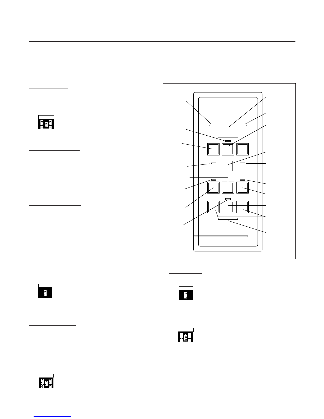
The SMX Keypad
SMX II and SMX Online Network
The SMX keypad is arranged for logical operation. The SMX II and SMX Online keypads are very similar, with
minor differences as noted below.
1. Data Display.
Large alphanumeric readout. Provides indication of
current setpoint, temperatures, programmed values
and error messages.
NET
SMX
Online
SMX Online Network Only
Provides scrolling readout of IDs for all
units. Provides data readouts for remote units.
2. Cooling Indicator.
Small LED to left of data display. Lights when bypass
valve is operating in cooling mode.
3. Heating Indicator.
Small LED to right of data display. Lights when
bypass valve is operating in heating mode.
4. Setpoint Indicator.
Small LED below data display. Lights when setpoint
is displayed. Off when inside or outside temperature
is displayed.
5. SET Key.
Press the SET key to display your currently selected setpoint (the temperature you wish to maintain
in the cabin ). You can display setpoint temperature
at any time, with the system off or on, without affecting other system operations.
SMX II
SMX II Only
The SET key also is used to dim the data
display readout. Press once to display setpoint.
Press again one or two times to dim the display.
6. UP-DOWN Keys.
Press UP or DOWN to raise or lower the setpoint.
Press once to change setpoint by one degree. Press
and hold to make larger changes. Note: if inside or
outside is being displayed (see TEMP), touching the
UP or DOWN key will cause the setpoint to be
displayed.
NET
SMX
Online
SMX Online Network Only
UP and DOWN keys are used to scroll
through ID numbers of all units in the network.
2. Cooling
Indicator
4. Setpoint
Indicator
6. UP-DOWN
Keys
8. Inside
Indicator
(SMX Online
& Net Only)
10. OFF Key
12. Run
Indicator
11. RUN
Key
16. Fan
Indicator
Cooling Heating
Down Set Up
Inside Outside
Temp
Run Off Aux Heat
Manual Mode
Slow Fan Fast
1. Data
Display
3. Heating
Indicator
5. SET
Key
7. TEMP
Key
9. Outside
Indicator
(SMX Online
& Net Only)
14. Aux Heat
Indicator
13. AUX HEAT
Key
15. FAN
Key
17. SLOW FAST
Keys
18. Fan
Speed
Indicators
7. TEMP Key.
Press once to display inside temperature.
SMX II
SMX II Only
Press TEMP a second time, and the
display will alternate between inside temperature
and setpoint. Press it a third time to return to
inside temperature only.
SMX
Online
SMX Online Network
Press TEMP a second time to display
outside temperature, if the optional outside
thermistor is installed with your system. Press a
third time for a rotating display of inside temperature, outside temperature and setpoint. Press a
fourth time to return to inside temperature only.
4
Hint
Normally, in an SMX Online Net system, a single out-
side thermistor is used to send temperature readings to
all of the SMX Online control panels. This means you’ll
get the same readout of outside temperature at all sta-
tions.
14. Aux Heat Indicator.
Small LED above AUX HEAT key. Lights when you
press the AUX HEAT key to select the aux heating
mode.
8. Inside Temperature Indicator.
SMX
Online
SMX Online Network
Small LED to left of TEMP key. Lights
when data display is showing inside temperature.
This LED is not available on SMX II.
9. Outside Temperature Indicator.
SMX
Online
SMX Online Network
Small LED to right of TEMP key. Lights
when data display is showing outside temperature if optional outside thermistor is installed. This
LED is not available on SMX II.
Hint
You can choose to display temperature in degrees Fahr-
enheit or Celsius. See page 13.
10. OFF Key.
Halts operation of the air handler. Note that the data
display remains on. You can continue to adjust
setpoint, display temperature readings and activate
the manual fan to circulate air while the air handler is
in the OFF mode.
11. RUN Key.
Turns the system on in the Run mode.
12. Run Indicator.
Small LED above RUN key. Lights when you press
the RUN key to select the Run mode.
Hint
Press both AUX HEAT and RUN at the same time, and
the system will automatically switch between cooling
and the aux heat mode. When in the automatic
switchover mode, both the RUN and AUX HEAT indica-
tors are lit.
15. FAN Key.
Controls fan operation. Selects manual or automatic
fan speed control. Press once to select manual
control. The LED above the key lights. Press FAN
again to select automatic fan speed control. In this
mode, the fan speed is controlled by the microprocessor as a function of the difference between
setpoint and inside temperature.
16. Manual Fan Indicator.
Small LED above the FAN key. Lights when fan is
running in manual mode.
17. SLOW-FAST Keys.
Control fan speed when the fan is in the manual
mode.
18. Fan Speed Indicators.
Row of five small LEDs below FAN key. Indicate the
current fan speed.
13. AUX HEAT Key.
Turns the system on in the heating only mode. If your
boat has auxiliary heating, the HEAT key is used to
select the aux heat mode. See page 9 for instructions.
Definitions
LED. Light Emitting Diode. An indicator or “pilot light”
used on the SMX to denote mode or operating status.
Setpoint. The selected temperature you want to main-
tain in the area being heated or cooled.
5
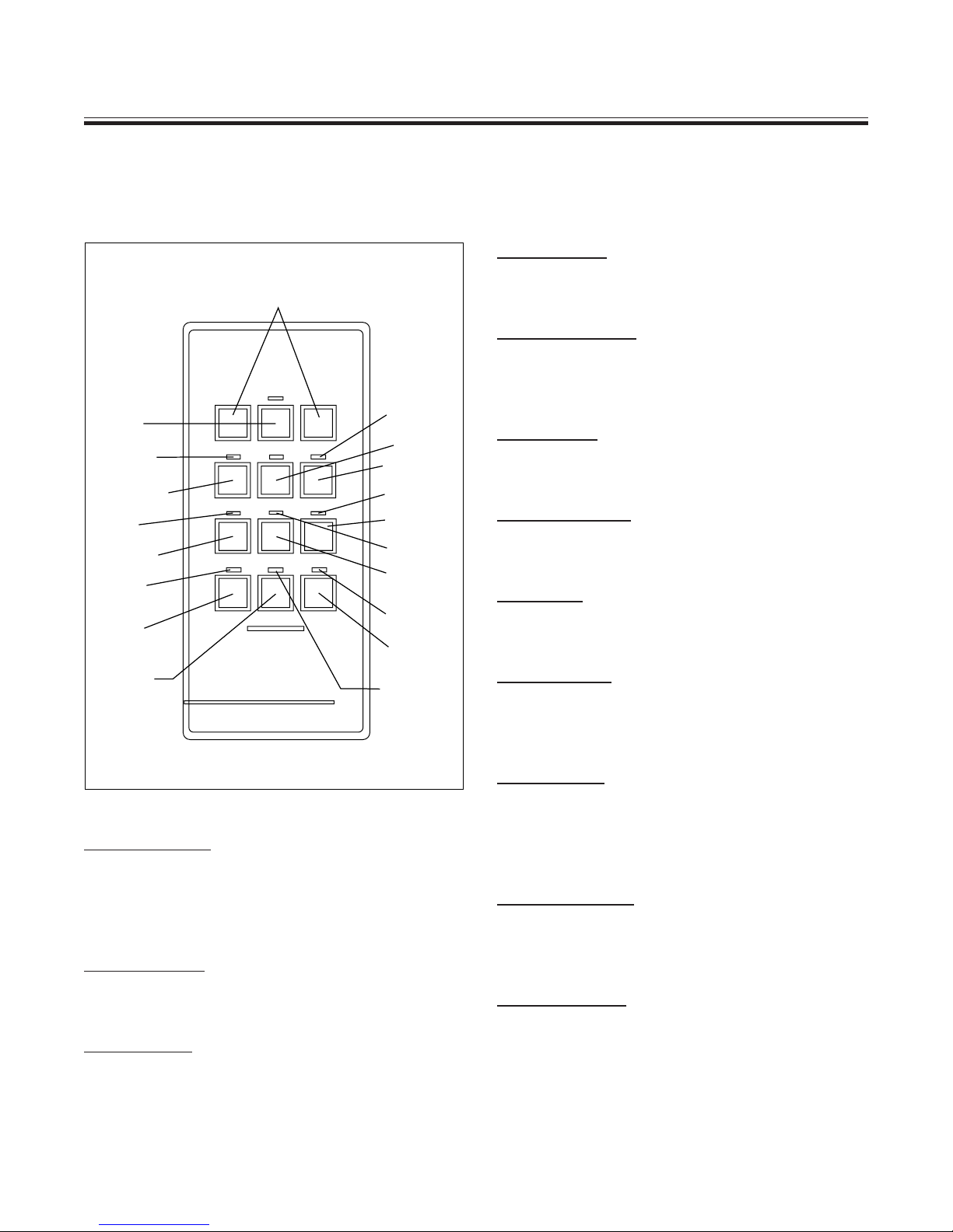
The Convenience Panel Keypad
SMX Online Network Only
The SMX Online Convenience Panel provides handy single-key control over many network functions. The
Convenience Panel is normally mounted adjacent to the SMX Online Net control panel.
4. PHONE Key.
Turns the telephone modem off and on.
1. SCROLL (up & down) Keys
5. Phone Indicator.
Small LED above the PHONE key. Lights when the
telephone modem is online.
2. REMOTE
Key
5. Phone
Indicator
4. Phone Key
9. Off
Indicator
8. OFF Key
15. Day
Indicator
14. DAY
Key
16. NIGHT
Key
▼
Scroll
Remote
Scroll▼
Phone Local Aux 1
Off Resume Lock
Night
Day
Absent
7. Aux 1
Indicator
3. LOCAL
Key
6. AUX 1
Key
11 Lock
Indicator
10. LOCK
Key
13. Resume
Indicator
12. RESUME
Key
19. Absent
Indicator
18. ABSENT
Key
17. Night
Indicator
1. SCROLL Keys.
Selects the remote unit to be controlled. Pressing the
left or right key scrolls through the controller IDs of all
possible systems in the network.
2. REMOTE Key.
Selects remote control mode.
3. LOCAL Key.
Select local display mode. Returns the SMX Online
switch to local operation.
6. AUX 1 Key.
Reserved for future applications.
7. Aux 1 Indicator.
Reserved for future applications.
8. OFF Key.
Turns off all SMX units on the network.
9. Off Indicator.
Small LED above OFF key. Lights when system is in
OFF mode.
10. LOCK Key.
Locks off all units in the network that are currently in
the OFF mode, rendering those local control panels
inoperative. To unlock press OFF and RESUME.
11, Lock Indicator.
Small LED above LOCK key. Lights when the LOCK
mode is engaged.
12. RESUME Key.
When in OFF mode, turns on the system so that all
SMX units in the network resume the mode they were
in when the system was turned OFF.
6

13. Resume Indicator.
Small LED above RESUME key. Lights when the
RESUME key is pressed.
14. DAY Key.
Selects the daytime operating mode. Places all units
in the network in the preprogrammed daytime configuration. See page 19 for programming.
15. Day Indicator.
Small LED above the DAY key. Lights when the
system is operating in the daytime mode.
16. NIGHT Key.
Selects the nighttime operating mode. Places all
units in the network in the preprogrammed nighttime
configuration. See page 19 for programming.
17. Night Indicator.
Small LED above the NIGHT key. Lights when the
system is operating in the nighttime mode.
18. ABSENT Key.
Selects the absent mode. Places all units in the
network in the preprogrammed absent configuration.
See page 19 for programming.
19. Absent Indicator.
Small LED above the ABSENT key. Lights when the
system is operating in the absent mode.
HintHint
Hint
HintHint
It’s a good idea to write down the DAY, NIGHT and AB-
SENT configurations to help you remember your pro-
grammed settings. Use the form on page 23 of this
manual.
7

Basic Operation
SMX II and SMX Online Network
POWER ON
When AC power is applied to the system at the
circuit breaker, the SMX microprocessor retrieves
from permanent memory the operating system
and the last operating configuration. This process
takes about four seconds, after which the system
will begin operating just as it had been when
power was last turned off.
SMX
Online
SMX Online Network
If your boat is equipped with the optional
outside thermistor, press TEMP a second time to
display outside temperature. Press a third time
for an alternating display of setpoint, inside
temperature and outside temperature. Note that
the inside and outside indicators show you which
temperature is being displayed.
SYSTEM OFF
Off
Press the OFF key to turn the system off. Note that
the data display remains energized even when the
system is off. Also, you can turn the fan on and off
manually when the system is in the off mode.
Note
The SMX has built-in protection against sudden power
interruptions. The system automatically stores the cur-
rent operating configuration in permanent memory ev-
ery time you make changes. When AC power is lost,
the SMX system retains these settings, and when AC
power is restored it resumes operation using the same
settings as before.
SELECTING SETPOINT
Press the SET key. The indicator above the key will
light, and the current setpoint will be displayed.
Press the UP or DOWN key to change the setpoint.
DISPLAYING TEMPERATURE
To display cabin temperature, press the TEMP key.
SMX II
SMX II Only
Press TEMP a second time for an
alternating display of inside temperature and
setpoint. Press a third time to return to inside
temperature only.
Set
Temp
SELECTING THE RUN MODE
Run
Press the RUN key. The Run Indicator above the
RUN key will light to show that you have selected the
run mode. Once the run mode has been selected
there are other parameters that determine how/when
the air handler will begin conditioning the air. They
are as follows:
For air handler to activate in cooling while in the run
mode the following conditions must exit:
• The tempering unit is in the cooling mode.
• The loop water temperature is below 65° F.
• The room temperature is above the setpoint of the
cabin control.
For air handler to activate in heating while in the
run mode the following conditions must exit:
• The tempering unit is in the heating mode.
• The loop water temperature is above 85° F.
• The room temperature is below the setpoint of the
cabin control.
SELECTING THE
AUX HEAT MODE
Aux
Heat
Press the AUX HEAT key. The Heat Indicator above
the AUX HEAT key will light to show that you have
selected the Aux Heat mode. For the Aux Heat mode
to function the following conditions must exist:
• The electric Aux Heater must be installed.
• The Aux Heat must be enabled.
(See Programming AUX HEAT, pg. 15)
• The room temperature is below the setpoint of
the cabin control.
NOTE: If the loop water temperature is above 85° F
the by-pass valve will also open allowing the hot
water to circulate through the coil at the same time
the electric aux heater is energized.
8
 Loading...