

Cruisair DX Installation & Operation Manual
DX Built-In Air Cooled A/C Systems v INSTALLATION • OPERATION 2
Distributed By:
DIRECT EXPANSION SYSTEMS
P.O. Box 430
Milford, VA 22514
Phone (804) 633-9454
FAX (804) 633-5499
Dometic Corporation
2000 N. Andrews Ave. Ext. • Pompano Beach, FL 33069-1497 USA
Phone: 954-973-2477 • Fax: 954-979-4414
Website: www.dometic.com/marine • Email: sales@dometicusa.com
Revised: 20140404
L-0261
For LP-10A

WARNING
This manual contains essential safety information
concerning the safe and proper installation of Cruisair
direct expansion air conditioning systems. It is very
important that you read and understand the contents of this
manual thoroughly before attempting to install any Cruisair
equipment. If there are any statements in this manual that
you do not understand, contact the Dometic Applications
Department for assistance. Phone 954-973-2477, Fax 954979-4414 (8:00 am - 5:00 pm United States EST).
NOTICE
As of July 1, 1992, United States federal law As of July 1,
1992, United States federal law prohibits the intentional
release of refrigerant gases into the environment, including
the R-22 refrigerant used in Cruisair air conditioning systems.
Special care must be taken when installing, charging
and servicing Cruisair equipment to prevent any loss of
refrigerant.
Cruisair does not recommend the practice of using
refrigerant to purge air and moisture from the system at
installation. This formerly used practice of purging is in
violation of United States federal law.
INTRODUCTION
This manual covers installation procedures for Cruisair
direct-expansion air conditioning systems.
In addition, there are specic installation sheets for some
models which may be shipped with Cruisair air conditioning
equipment, providing additional details for specic
components.
2

Table of Contents
Chapter 1: Description of Basic Components ...........................................................................................4
Basic Principles ..............................................................................................................................4
Cooling Unit ....................................................................................................................................4
Controls/Switches ...........................................................................................................................4
Condensing Unit .............................................................................................................................4
Figure 1. SA 3 Series Control..........................................................................................................4
Figure 2. SMX Series Keypad ........................................................................................................4
Chapter 2: Installation of Basic Components ............................................................................................5
Cooling Unit ....................................................................................................................................6
Control or Switch Assembly ............................................................................................................6
Condensing Unit .............................................................................................................................6
Installation Kit .................................................................................................................................7
Figure 3. Minimum Grill and Free Air ..............................................................................................5
Figure 4. Diagram of Flared Joint ...................................................................................................7
Figure 5. Refrigerant Line Sizes .....................................................................................................8
Chapter 3: Start-Up Procedures - Final Inspection ...................................................................................9
Figure 6. Wire and Breaker Size .....................................................................................................9
Chapter 4: Start-Up Procedures - Initial Charging of A New System ......................................................10
Required Tools ..............................................................................................................................10
Field Charging a System .............................................................................................................. 11
Removing Refrigerant from a System ...........................................................................................11
Figure 7a. Charging Pressure Charts for Equipment Built in 1994 and After ................................12
Figure 7b. Charging Pressure Charts for Equipment Built Prior to 1994 ....................................... 13
Chapter 5: Start-Up Procedures - Final Check-Out and Start-Up ........................................................... 14
Chapter 6: General Operation ................................................................................................................15
Operating Instructions - Rotary Knobs .........................................................................................15
Operating Instructions - SMX Series Controls..............................................................................16
Chapter 7: Maintenance .........................................................................................................................17
Cooling Unit and Switch Assembly ...............................................................................................17
Condensing Unit ...........................................................................................................................17
Chapter 8: System Failure Troubleshooting Guide .................................................................................. 18
Chapter 9: System Charging Troubleshooting Guide ..............................................................................19
Chapter 10: Installation Wiring Diagrams ................................................................................................20
Index of Diagrams ........................................................................................................................20
Warning ..................................................................................................................................................31
3
CHAPTER 1: Description of Basic Components
Cooling
Heating
Down Set Up
Inside Outside
Temp
Cool Off Heat
Manual
Mode
Slow Fan Fast
Basic Principles
The Cruisair air conditioning system consists of
three basic components and, in some cases,
several accessory parts. They are: (1) cooling
unit; (2) control or switch assembly; and (3)
condensing unit. This instruction manual will
describe and explain the function of the basic
parts of a Cruisair system and will outline the
installation, interconnection and startup of a
complete system. It also includes maintenance
and operation of Cruisair equipment in general.
Cooling Unit
The cooling unit is a refrigerant to air heat
exchanger coupled to a fan or blower which is
located in the space to be cooled. A cooling unit
is sometimes referred to as an ‘evaporator’ or a
‘cooling coil’, but in this manual, we will use the
term ‘cooling unit’. The cooling unit is constructed
of a series of copper tubes held in place by
vertical aluminum ns. Inside these tubes, the
refrigerant expands to produce a chilling effect
by absorbing the heat in the air. This air is forced
through the coil by the fan or blower.
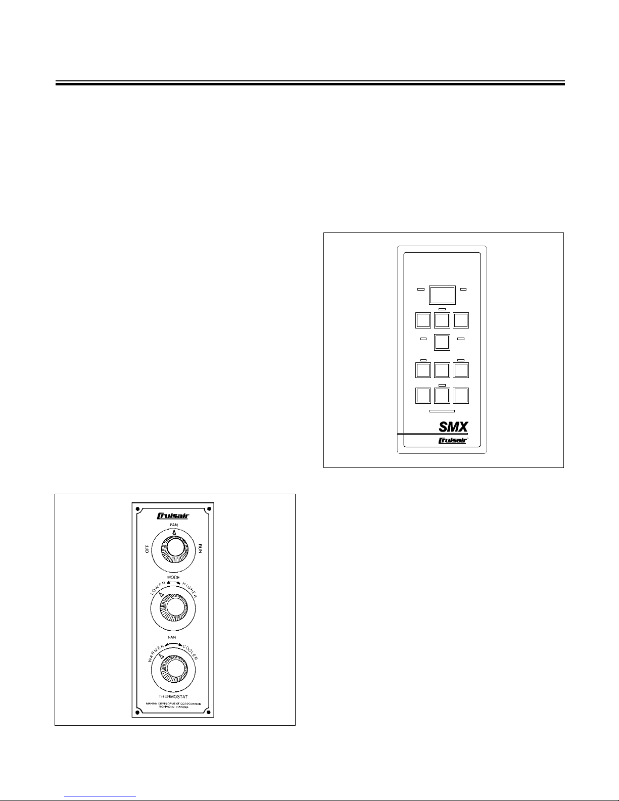
SA type switch assembly has rotary knobs for
controlling the system. Figure 1 shows a typical
SA switch assembly.
The SMX series controls are advanced
microprocessor based systems, with more
than 20 user programmable functions. These
functions are described in the SMX series
owner’s manuals. Figure 2 shows an SMXII
control panel.
77
Controls/Switches
There are two basic types of controls and
switches used with Cruisair systems: the SMX
series of microprocessor controls and the SA
family of rotary knob switch assemblies. The
Figure 1. SA 3 Series Control
Figure 2. SMX Series Keypad
Condensing Unit
The condensing unit consists of the
refrigerant compressor, the refrigerant
receiver, the refrigerant to air heat exchanger
or condenser, condenser fan or blower, the
associated electrical components, and the
system service valves.
The basic function of the condensing unit is to
compress the expanded refrigerant, owing back
from the cooling unit to the compressor, to a high
pressure state. The compressed refrigerant then
passes through the heat exchanger (condenser
coil) where it gives up the heat which was
absorbed in the cooling coil. It is then condensed
to a liquid state as it ows to the liquid receiver
and the process of ow back to the cooling unit
is repeated.
4
CHAPTER 2: Installation Of Basic Components
The following instructions should be followed,
in their proper sequence, when installing
Cruisair equipment. Read and understand the
instructions in this manual before proceeding.
Cooling Unit
In all installations, the cooling unit must be
installed so the air discharge grill is installed as
high as possible, (minimum three feet above the
oor level). The cooling unit must be installed
with the condensate drip pan positioned at the
bottom of the unit so the water dripping from the
evaporator coil collects in it before discharging
to a suitable drain outside. The cooling unit drain
must be installed so the drain tube makes an
immediate 1” drop after leaving the drain tting.
With discharge air grills located high, return
air grills should be located as close to the oor
as possible to provide the best pattern of air
ow. Avoid locating the return air grill in close
proximity to the discharge grill since the resulting
short circuiting effect of the air ow will impair
the effectiveness of the system.
Cooling units with model number prexes
EFB, EBH, or EFL should be mounted as high
as possible, directly behind the discharge grills.
Centrifugal or blower type cooling units,
model number prexes EBS, EBO, EHBO, EBL
or EHBL, should be mounted low, near the
return air grill, and the discharge air ducted to
the discharge grill mounted at a high level.
The cooling unit must be installed so there
is an adequate path for the air to re-circulate
freely into the unit from the space being cooled.
It is important that the cross sectional area of all
discharge grills be at least equal to the coil face
area of the discharge of the cooling unit involved.
An exception is the centrifugal blower type
cooling unit.
The cross sectional area refers to the ‘free air’
area of a discharge air grill rather than the total
area as determined by the overall measurement
of the grill itself. For instance, if a grill is made of
expanded metal, perhaps only 50% of the area
is open for the passage of air. The metal web
itself will block air from passing through the other
50%. In such cases, the total area of the grill must
be doubled to achieve the required open area.
Observe this carefully when selecting a grill.
The return air grills used should be the
type which have removable lters so they
EVAPORATOR DUCT GRILL AREA FREE AIR AREA
Type BTU’s Size In. Return (Sq. In.) Supply Return (70%) (Sq. In.) Supply (60%)
EBL 16,000 2 @ 5 144 2 @ 49 101 2 @30
EBO 4,000 4 64 32 45 19
7,000 5 72 49 51 30
10,000 6 100 60 70 36
14,000 7 144 80 101 48
16,000 7 144 80 101 48
EBS 14,000 7 144 80 101 48
16,000 7 144 80 101 48
EFB 10,000 NA 100 100 70 60
14,000 NA 144 144 101 87
16,000 NA 144 144 101 87
EBH 14,000 NA 144 144 101 87
16,000 NA 144 144 101 87
EFL 1,000 NA 40 40 28 24
14,000 NA 128 128 90 77
16,000 NA 128 128 90 77
Figure 3. Minimum Grill and Free Air
Minimum Grill And Free Air Area
5

can be removed and cleaned easily. The lter
material should be a type which will not cause
a signicant inlet air ow pressure drop. For
all discharge air applications, wood or plastic
frames are recommended. Aluminum frame grills
will become cold and may produce secondary
condensation that will drip from the grill frame.
See Figure 3 to determine the minimum grill
and free air areas for each model cooling unit.
Control or Switch Assembly
The control or switch assembly is supplied as
a separate item. The rotary switch assembly has
three knobs and the plate is printed either for
horizontal or vertical installation. It is designed
to be mounted in an opening cut on the job and
is fastened from the front with four screws. The
wiring from the switch assembly terminates
in a color coded terminal strip that should be
securely mounted in a suitable place. Electrical
connections for all systems are typically the
same.
Operation of the SA type controls is covered
in Chapter 6.
Condensing Unit
Cruisair condensing units are designed to
be installed in a compartment ventilated to
the outside. Air entry and exit openings to the
exterior should be protected by rain proof louvers
or grills. Space should be provided on all sides
of the unit to allow air to enter it for cooling
the condenser. All refrigeration components
are hermetically sealed and all electrical
components are spark proof for maximum safety.
Make sure the wood base is positioned at the
bottom of the unit in a horizontal plane. Fasten
the condensing unit wood base securely and
in such a way that the unit can be removed for
service if necessary.
ACA Series Condensing Units
Return Air
Minimum Grill Area Free Air (70%)
240 sq. in. 168 sq. in.
The thermostat in the switch assembly has
a 10 foot capillary tube leading from it to the
temperature sensing bulb. This bulb must be
located in the system’s return air stream so that
the bulb is exposed only to the air returning from
the space being cooled.
The SMX control system uses a Temperature
Sensing Element (TSE) to control the operation
of the system. Like the thermostat bulb on the
SA type control, this TSE must be installed in
the return air path of the conditioned air. These
sensors are available in various lengths from 10
to 80 feet.
Operation of the SMX type controls is covered
in the SMX Series Control Systems User’s
Guide, L-634.
6
Installation Kit
1. Copper Tubing
When installing the two connecting copper tubes
between the cooling unit and the condensing unit,
there are several important factors to consider.
First, the tubing can be run in lengths up to 50 feet.
It can run uphill, downhill, or sloping, as required
and can have as many bends as necessary. (Avoid
sharp bends and do not use soldered elbows.) Both
the suction and discharge lines should be insulated
individually to prevent moisture from forming on the
tube and for vibration protection. Also insulate the
connecting are nut joints carefully to prevent drip
ping of moisture from these joints.
-
Caution • • • • • • • • • • • • • •
Always use refrigeration grade, seamless,
soft copper tubing. Never use neoprene,
rubber or any other type hose not de
signed specically for use with R-22 and
approved by Cruisair. The refrigerant used
in Cruisair systems is monochlorodiuoromethane or R-22. This gas is compatible
with very few tube compositions with
copper being the most frequently used.
(Engine driven systems use a different
type refrigerant so therefore can use a
neoprene refrigerant lines.) The copper
tubing is connected to the cooling unit
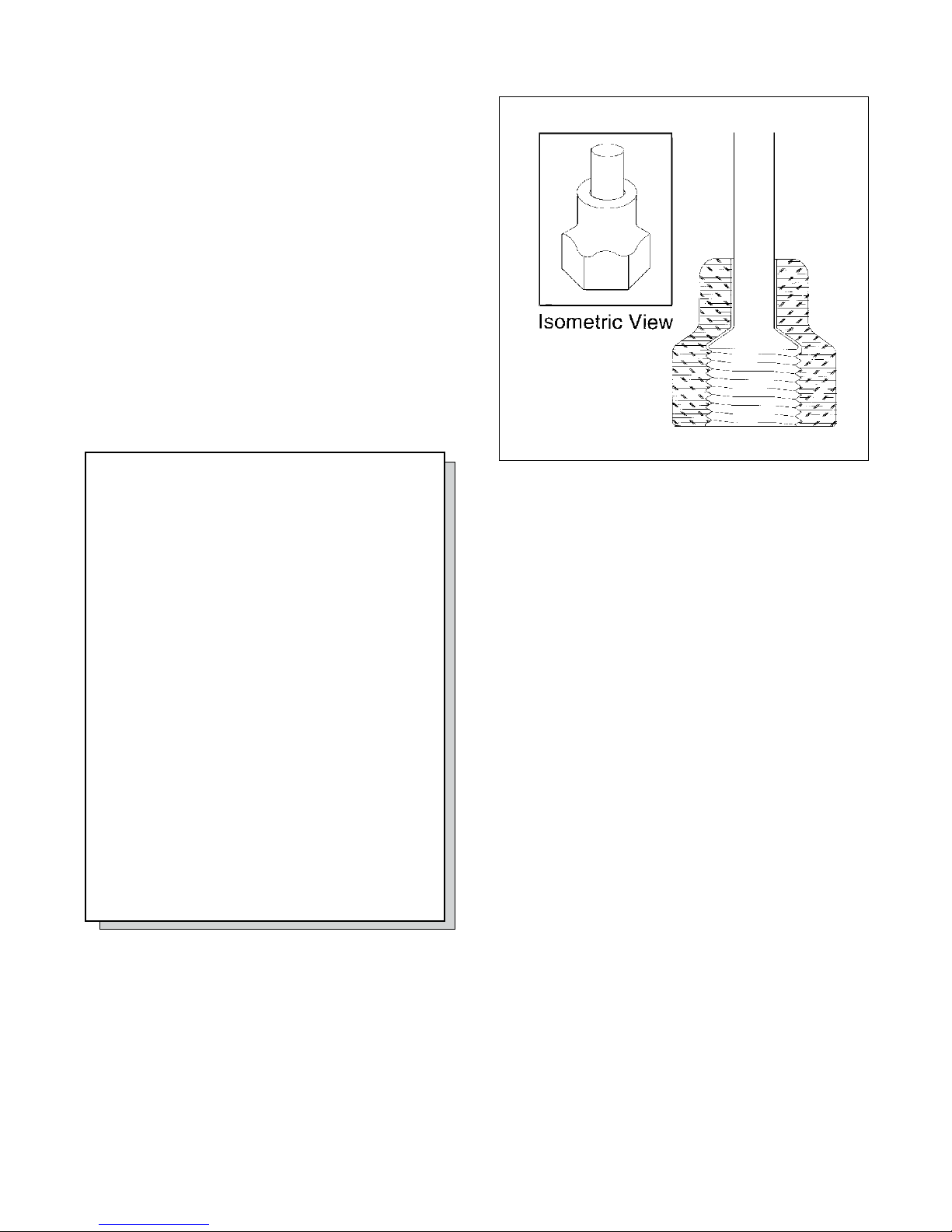
and condensing unit with are joints.
Flares of exceptional quality are essential
to prevent refrigerant leaks. Flares must
be of the 45°, single are type. Do not use
a double are. The are should be large
enough in diameter to ll the are nut
completely. See Figure 4.
-
Figure 4. Diagram of Flared Joint
Only the long stem forged are nuts, such as
those that are supplied with Cruisair equipment,
are strong enough for mobile duty. Do not use long
stem machined are nuts. Flare nuts should be
tightened until the nut ceases to offer resistance to
tightening. This is the point where the ared portion
of the copper tubing is beginning to ow or mash
under the force of the nut being tightened. After
the tubing is insulated and in place, secure it with
clamps. For proper line sizes, see Figure 5.
2. Wire Harness
SA Series Controls
The wire harness connects the condensing unit
to the main switch assembly terminal strip. The
harness or cable should include six conductors.
Normally the wire harness is run along with the
connecting copper tubing but this is not necessary.
SMX Series Controls
An interconnect cable (CX) is available in various
lengths from 10 to 80 feet. The cable includes a
plug on each end for ease of installation. The SMX
series also uses an electronic temperature sensor
which comes in various lengths and it too plugs in.
7
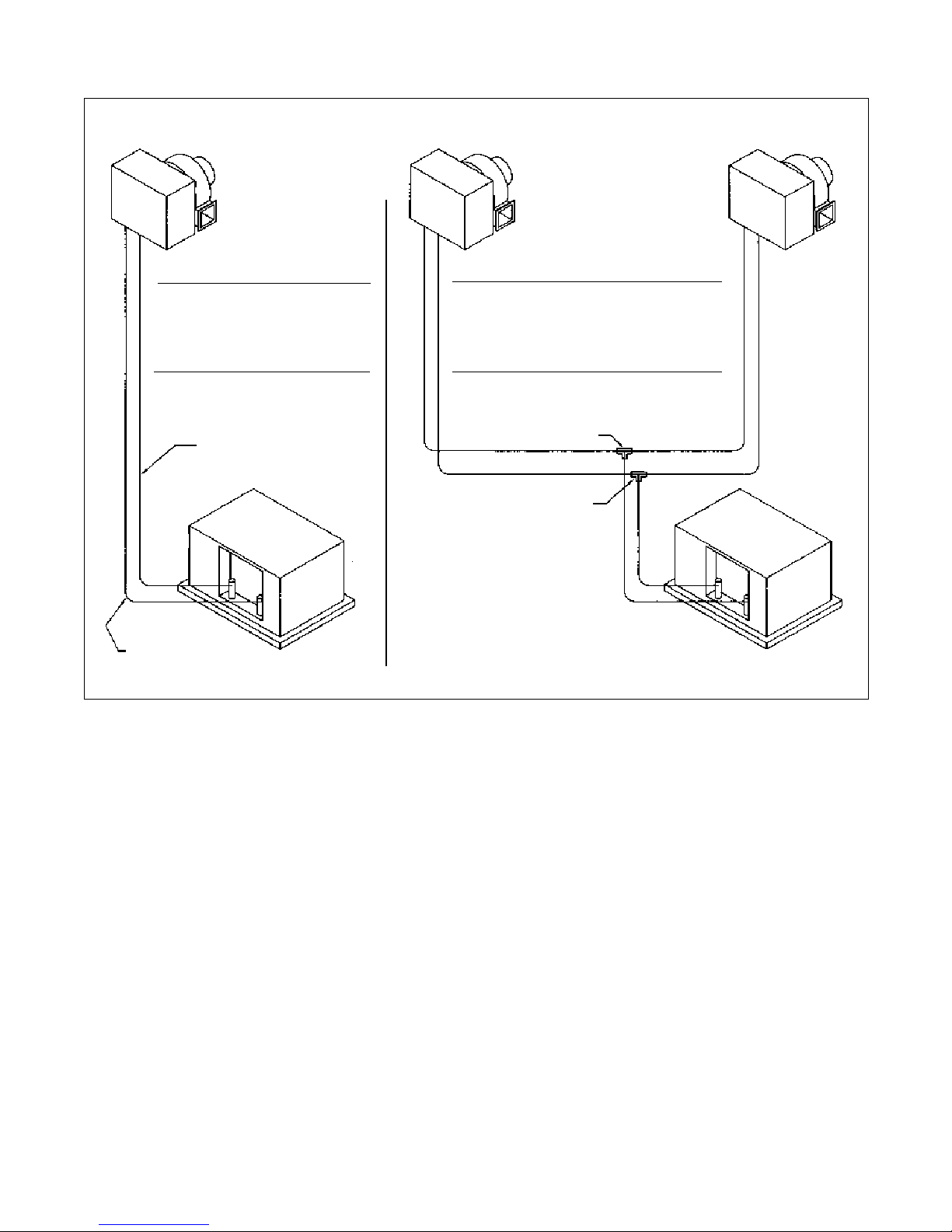
Air Conditioning System
with (1) Cooling Unit
& (1) Condensing Unit
Air Conditioning System
with (2) Cooling Units
& (1) Condensing Unit
Suction Lines
Unit Cap Line Size
14000 BTU - 1/2”
16000 BTU - 1/2”
Discharge Lines
14000 BTU - 1/4”
16000 BTU - 1/4”
Suction Line
Discharge Line
Cooling Unit Line Sizes
Unit Cap Suction Discharge
4000 BTU - 3/8” 1/4”
7000 BTU - 3/8” 1/4”
10000 BTU - 3/8” 1/4”
Condensing Unit Line Sizes
14000 BTU - 1/2” 1/4”
Discharge Tee
1/4” X 1/4” X 1/4”
Suction Tee
3/8” X 3/8” X 1/2”
Notes:
1) Insulate entire length of both
refrigerant lines with closed
cell foam or equivalent
2) All tubing should be seamless
refrigeration grade copper
3) Tee’s (where applicable)
should be within 2-3 ft. of
condensing unit
Figure 5. Refrigerant Line Sizes.
8

CHAPTER 3: Start Up Procedures - Final Inspection
The following is a list of items to be checked
before any Cruisair system is started. Be sure
that the:
p Cooling unit is bolted securely in place.
p Cooling unit return air cross sectional
open area is equal to the face area of the unit
evaporator coil as a minimum
p Return air to the cooling unit should pass
through a lter and should come only from the
space being cooled.
p Switch assembly terminal strips are securely
mounted in a dry place, safely out of reach, and
covered.
p Thermostat temperature sensing bulb or
temperature sensing element (TSE) is installed
in the cooling unit return air stream. NOTE:
These should not be touching metal parts of the
cooling unit which may become cold.
14,000 BTU/hr Condensing Unit
Voltage 115 230
Wire size 10 12
Breaker size 30 20
Figure 6. Wire and Breaker Size
p Power line from the vehicle’s panel is
connected securely to the condensing unit
terminal strip. See wiring diagram. Be sure the
proper size circuit breaker of the time delay type
is installed. See Figure 6 for proper wire and
breaker sizes.
p The refrigerant lines between the cooling unit
and condensing unit are insulated completely.
p Copper tubes and wire harness are secured
throughout their length.
p Condensing unit is securely mounted.
p Cooling unit condensate drain is in place and
working properly. Test by pouring two quarts of
water rapidly into the cooling unit drip pan.
p Cooling unit wires are connected securely to
the condensing unit terminal strip.
p Flare nut joints at the cooling unit are tight.
p Flare nut joints at the cooling unit are
insulated to prevent dripping. Insulate after
testing for leaks.
p Wire harness to the condensing unit is
securely connected to the switch assembly
terminal strip.
p Flare joints at the condensing unit are tight
and insulated, after testing for leaks.
9
CHAPTER 4: Start Up Procedures - Initial Charging Of A New System
Warning • • • • • • •
Federal law prohibits the intentional
release of refrigerant gas into the
environment and requires that you use
EPA approved refrigerant handling
equipment and procedures to prevent any
refrigerant gas from escaping into the air.
The following instructions should be followed in
evacuating and charging a Cruisair remote con
densing unit system with R-22.
There are three refrigerant circuit components
in a Cruisair remote condensing unit system: the
condensing unit, the cooling/heating unit and
the copper refrigerant lines. The condensing
unit is shipped from the factory charged with
approximately the amount of refrigerant needed for
the whole system. The cooling unit is pressurized
with dry nitrogen and the copper tubing contains air.
The procedure will be to evacuate the nitrogen
and air from the cooling unit and the copper tubing,
then release the refrigerant from the condensing
into the entire system. To facilitate this procedure,
there is a special port with a red cap located on the
right hand base valve of the condensing unit.
Required Tools
• Refrigerant 22 container (typically the
disposable type container color coded green
for R-22)
• Four valve gauge manifold with self closing
ttings on the charging hoses
• Vacuum pump
• Base valve wrench and hand tools
• Accurate thermometer
Proceed as Follows
1. Make sure all are joints are well made and
tight.
2. Do not touch the condensing unit base valve
stem covers or service port caps. Remove the
red port cap on the right hand base valve.
3. Connect the vacuum pump hose to the
vacuum pump. Connect the refrigerant supply
line to the refrigerant container (make sure
the container valve is OFF). Connect the low
pressure gauge hose, equipped with self
closing ttings to the red capped port. At
this point do not connect the high pressure
charging hose to anything.
4. Close all gauge manifold valves.
5. Energize the vacuum pump and open manifold
valves for the vacuum pump, the refrigerant
container, and the red capped access port low
pressure test gauge).
6. As the pump operates, you will see the low
pressure test gauge fall to a vacuum. When he
vacuum reaches 28 in. HG, close the vacuum
-
pump valve and turn the vacuum pump off.
Leave the system for 15 minutes and then
observe the gauge. If any vacuum is lost, a
leak is indicated. Find the source of the leak
and correct. Return to step #3 above and
re-evacuate the system. Continue until the
system will hold the vacuum.
7. Open the vacuum pump valve and leave the
vacuum pump operating for at least 6 hours
or until a vacuum of at least 29 in. HG is
achieved. Close the vacuum pump valve and
turn the vacuum pump off. Wait one hour. If
no vacuum is lost, proceed with charging. If
any vacuum is lost, a leak is indicated. Find
the source of the leak and correct. Return to
step #3 above and re-evacuate the system.
Continue until the system will hold the
vacuum.
8. Open the refrigerant container valve slowly
and allow gas to enter the system until the
gauge rises to zero. You have now lled the
evacuated lines and cooling/heating unit with
refrigerant to a gauge pressure of zero. Close
the refrigerant container valve.
9. Remove the low pressure gauge hose from
the red capped port. Replace and tighten the
red cap.
10. Remove both condensing unit base valve
stem caps. Open both base valves fully by
turning the valve seems fully counterclock
wise. This will allow the refrigerant in the
condensing unit to enter the system. Replace
and tighten the valve stem caps.
At this point, the system is basically charged and
ready for nal gas charge adjustment.
10
 Loading...