

Page 1
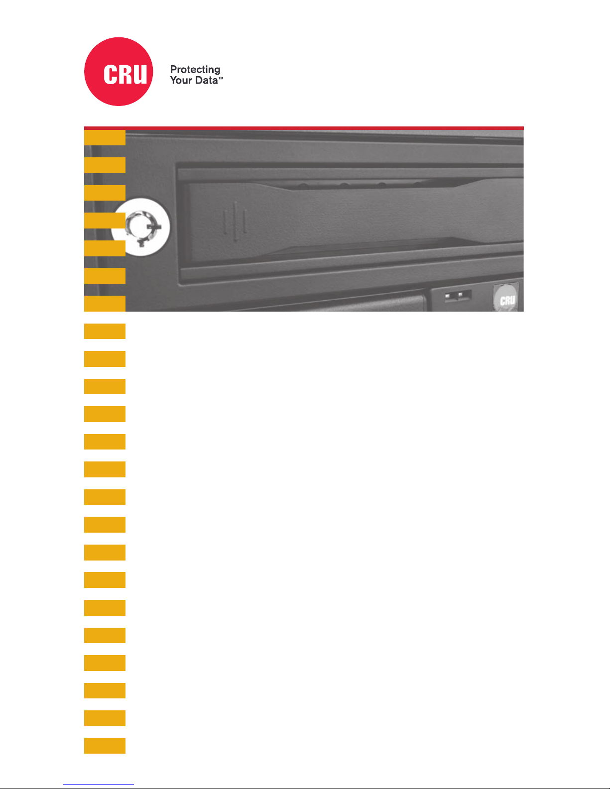
Data Express® DX115 DC
Quick Start Guide
Features
• Rugged all-metal construction protects drive during transport
• Carrier inserts quickly and easily into CRU® DX115 DC frames in
digital cinema servers or ingestion racks
• Industry standard for global digital cinema/content distribution
• Auto Start feature powers up the drive seconds after installing the
carrier without having to push the power button
• Rated for up to 30,000 carrier insertions
Page 2

Data Express DX115 DC Quick Start Guide
1. Installation Steps
1.1 Frame Installation
a. Slide the DX115 DC frame into an open 5.25-inch drive bay on your server or ingestion system.
b. Secure the frame to the chassis with the mounting screws provided.
c. Attach a SAS or SATA data cable to the data connector on the rear of the frame. Attach the other
end to the appropriate SAS or SATA port on the server or ingestion system.
d. Attach a SATA power connector to the rear of the frame.
1.2 Hard Drive Installation
a. If the carrier is locked into the frame, insert a Data Express Key into the lock and turn it 90
degrees clockwise.
b. Push in on the ejection handle of the carrier to pop it out. Use the handle to remove the carrier
from the frame.
c. Use a Phillips screwdriver to remove the two screws securing the carrier cover. The screws are
located on either side of the front of the carrier.
d. Remove the cover and attach a 3.5-inch or 2.5-inch drive to the unified power and data connector
inside of the carrier.
e. With one hand on the top of the drive, turn the carrier over. Then secure the drive to the carrier
using the mounting screws provided.
f. Reattach the carrier cover and secure it using the two screws you removed in Step C.
2 Operating Your DX115 DC
2.1 Basic Operation
a. Slide the DX115 DC carrier into the frame, then push the carrier handle in until it clicks. After a
few seconds, the DX115 DC will automatically start up.
b. You may optionally secure the carrier to the frame. Insert the included Data Express Key into the
keylock and turn it 90 degrees counter-clockwise.
Your DX115 DC is now ready to use! If the drive inside is already formatted, it can be used right away.
If the drive is brand new or its format is not compatible with your computer, the drive will need to be
formatted before being used.
Formatting a drive will erase all data on the drive, so be sure to back up your data before
beginning this operation.
2
Page 3

Data Express DX115 DC Quick Start Guide
2.2 Safe Carrier Removal
a. Power off the unit by pressing the power button.
To prevent the possibility of losing data, ensure there are no file transfers in progress and
the amber Drive Activity LED is off before turning off the DX115 DC.
b. Use the DataExpress Key to turn the keylock 90 degrees clockwise to unlock the unit.
c. Push in on the ejection handle of the carrier to pop it out. Use the handle to remove the carrier
from the frame.
3 Other Configuration Options
3.1 LED Activity
LED Name Color State Description
Drive Ready/Error Blue/Red Flashing Blue Carrier is inserted and the drive inside is powering up.
Solid Blue Drive is powered on and ready for access.
Flashing Red and Blue Fan failure. Please contact Technical Support.
Solid Red DC power failure. Please contact Technical Support.
Drive Activity Amber Flashing Indicates when the host computer is accessing data
on the drive.*
*Some SATA PC systems/host controllers provide support for the Drive Activity LED feature (refer to the SATA PC system/host controller
manufacturer’s documentation for further information). The Drive Activity LED can be enabled via host connection (cable not included) to
Pin 1 located on the receiving frame motherboard. Refer to the SATA PC system/host controller manufacturer’s documentation for further
information.
3.2 Fan Error LED Disable Switch
This switch allows the user to disable the Fan Error LED. It is a pinhole located on the front of the
DX115 DC frame just above the power button. Insert a paper clip or similar object to activate the
switch. CRU recommends replacing a faulty fan immediately. Contact Technical Support to obtain a
new fan.
3.3 Power Button
The DX115 DC ships with the Auto Start feature permanently enabled, which automatically spins up a
drive upon insertion of the carrier. Use the Power Button to power down or power up the drive inside
the carrier without ejecting and reinserting it first.
3.3 Jumper Chart
The following jumper chart indicates the functionality for each position on the jumper block located on
the rear of the DX115 DC.
HDD LED
Activity Disable
Reserved
Pins
Host Activity
LED Pin
Ground
2
1 345
6
3
Page 4

Part Number: A7-115-0003-1 Rev. 1.0
Product Models DataExpress DX115 DC
Interface Types & Speeds SATA: up to 6 Gbps
SAS: up to 6 Gbps
Supported Drive Types 2.5-inch and 3.5-inch SATA hard drives and SSDs
2.5-inch and 3.5-inch SAS hard drives and SSDs
Data Connectors One (1) SATA connector
Insertion Rating Up to 30,000 carrier insertions
Torque 2.5-inch drives, M3 screws: 4 inch-pounds max.
3.5-inch drives, #6-32 screws: 6 inch-pounds max.
Supported Operating Systems Windows 10, 8, and 7
Windows Server 2016, 2012 and 2008 product families
OS X/macOS 10.11 “El Capitan” or newer
Linux distributions that support the connection type used
Compliance EMI Standard: FCC Part 15 Class B
EMC Standard: EN55022, EN55024
CE, RoHS
Product Weight Unpopulated: 2.7 pounds (1.22 kg)
Populated: 4.2 pounds (1.91 kg)
Product Dimensions 5.75in W x 8.07in L x 1.61in H (146mm W x 205mm L x 41mm H)
Technical Support Your investment in CRU products is backed up by our free technical support for the
lifetime of the product. Contact us through our website, cru-inc.com/support or call
us at 1-800-260-9800 or +1-360-816-1800.
©2018 CRU Acquisition Group LLC, ALL RIGHTS RESERVED. CRU® and Data Express® are trademarks of CRU Acquisition Group, LLC and are
protected by trademark law.
Product Warranty
CRU warrants this product to be free of significant defects in material and workmanship for a period of five years from the original date of purchase.
CRU’s warranty is nontransferable and is limited to the original purchaser.
Limitation of Liability
The warranties set forth in this agreement replace all other warranties. CRU expressly disclaims all other warranties, including but not limited to, the
implied warranties of merchantability and fitness for a particular purpose and non-infringement of third-party rights with respect to the documenta
tion and hardware. No CRU dealer, agent, or employee is authorized to make any modification, extension, or addition to this warranty. In no event will
CRU or its suppliers be liable for any costs of procurement of substitute products or services, lost profits, loss of information or data, computer mal
function, or any other special, indirect, consequential, or incidental damages arising in any way out of the sale of, use of, or inability to use any CRU
product or service, even if CRU has been advised of the possibility of such damages. In no case shall CRU’s liability exceed the actual money paid
for the products at issue. CRU reserves the right to make modifications and additions to this product without notice or taking on additional liability.
FCC Compliance Statement: “This device complies with Part 15 of the FCC rules. Operation is subject to the following two conditions: (1)
This device may not cause harmful interference, and (2) this device must accept any interference received, including interference that may cause
undesired operation.”
This equipment has been tested and found to comply with the limits for a Class B digital device, pursuant to Part 15 of the FCC Rules. These limits
are designed to provide reasonable protection against harmful interference when the equipment is operated in a home or commercial environment.
This equipment generates, uses, and can radiate radio frequency energy and, if not installed and used in accordance with the instruction manual,
may cause harmful interference to radio communications.
In the event that you experience Radio Frequency Interference, you should take the following steps to resolve the problem:
1) Ensure that the case of your attached drive is grounded.
2) Use a data cable with RFI reducing ferrites on each end.
3) Use a power supply with an RFI reducing ferrite approximately 5 inches from the DC plug.
4) Reorient or relocate the receiving antenna.
1000 SE Tech Center Dr. Suite 160, Vancouver WA, 98683
 Loading...