

Page 1
Data Express® DE110 SATA 6G
Quick Start Guide
Features
• Supports SATA hard drives and SDDs in both 2.5-inch and 3.5inch form factors
• Supports file transfer speeds up to 6 Gbps
• All-metal design dissipates heat while ensuring the safety of your
data
• Rated for up to 25,000 carrier insertions
Page 2
Data Express DE110 SATA 6G Quick Start Guide
1 General Information
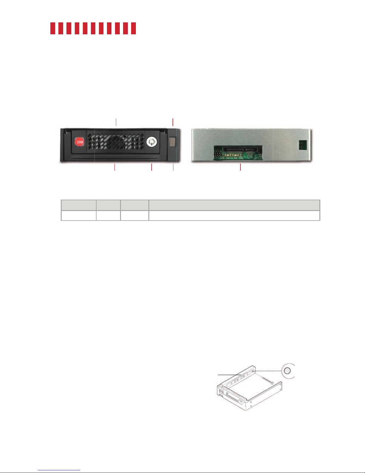
1.1 Identifying Parts
1.2 Indicator Behavior
Indicator Color State Description
Drive Activity Blue Blinking The drive inside the carrier is being accessed by your computer.
2 Frame Installation
a. Slide the receiving frame into an open 5.25-inch bay.
b. Use a Phillips screwdriver to secure the receiving frame to the chassis with the provided screws. If the
bay appears too large, you can position an included spacer plate in between the frame and the chassis
on each side before you secure the frame to the chassis.
c. Attach a SATA data cable to the SATA port on the rear of the receiving frame and the other end to the
corresponding SAS or SATA port on the computer’s motherboard.
d. Attach a SATA power connector from your computer to the SATA power port on the rear of the
receiving frame. If no SATA power connectors are available, attach the included Molex-to-SATA
adapter cable to a Molex power plug. Then plug the SATA end of the adapter cable into the rear of
the receiving frame.
Optional: Display ID Selection
The Display ID on the front of the frame is for
display purposes only and does not provide any
other functionality. To set it, follow these instruc-
tions.
a. Insert the provided Data Express Key into
the keylock and turn it 90 degrees counter-
clockwise to power on the frame.
2
Display ID
Select Switch
Drive Carrier
Guide
Figure 1. Display ID Switch Location
Front
Display ID &
Drive Activity LED
FrameCarrier Handle
Rear
SATA Power and
Data Connectors
Keylock
Carrier
Page 3

Data Express DE110 SATA 6G Quick Start Guide
b. Use the provided flathead screwdriver to select the display ID number (see Figure 1). Rotating the
switch will cycle the display through 1-9 and A-F.
c. Power off the frame with the provided Data Express Key by inserting it into the lock and turning
it 90 degrees clockwise.
3 Drive Installation
a. If the carrier is locked into the frame, insert a Data Express Key into the lock and turn it 90
degrees clockwise.
b. Pull the carrier from the frame.
c. Use a Phillips screwdriver to remove the two screws on the rear of the carrier that are securing
the cover. Then remove the cover.
d. Insert your 2.5-inch or 3.5-inch drive into the carrier and use four of the provided Phillips #6-32
flat head screws to secure it.
e. Replace the drive carrier cover and secure it using the screws you removed in Step 3c.
4 Operating Your DE110
4.1 Basic Operation
a. Slide the DE110 carrier into the frame.
b. Insert the provided Data Express Key into the keylock and turn it 90 degrees counterclockwise to
secure the carrier to the frame and power on the drive inside.
Your DE110 removable drive enclosure is now ready to use! If the drive inside is already formatted, it
can be used right away. If the drive is brand new or its format is not compatible with your computer, the
drive will need to be formatted before being used.
Formatting a drive will erase all data on the drive, so be sure to back up your data before
beginning this operation.
4.2 Safe Carrier Removal
a. Turn off the computer or properly dismount the drive from the system. To dismount the drive,
ensure there are no file transfers in progress and the amber Drive Activity LED is off before
turning off the DE110, or use a third party SATA hotswap utility.
b. If the carrier is locked into the frame, insert a Data Express Key into the lock and turn it 90
degrees clockwise.
c. Remove the carrier from the frame.
3
Page 4

Part Number: A7-110-0009-1 Rev. 1.0
Product Models Data Express DE110 SATA 6G
Interface Types & Speeds SATA: up to 6 Gbps
Supported Drive Types 3.5-inch SATA hard drives and SSDs
Data Connectors One (1) SATA connector
Insertion Rating Up to 25,000 carrier insertions
Torque 2.5-inch drives, M3 screws: 4 inch-pounds max.
3.5-inch drives, #6-32 screws: 6 inch-pounds max.
Description of LEDs Seven segment display with drive activity indicator
Supported Operating Systems Windows 10, 8, and 7
Windows Server 2016, 2012 and 2008 product families
OS X/macOS 10.11 “El Capitan” or newer
Linux distributions that support the connection type used
Compliance EMI Standard: FCC Part 15 Class B
EMC Standard: EN55024, EN55032
CE, RoHS
Product Weight 2.9 pounds (1.32 kg)
Product Dimensions 5.73in W x 8.66in L x 1.61in H (145.5mm W x 220mm L x 41mm H)
Technical Support Your investment in CRU products is backed up by our free technical support for the
lifetime of the product. Contact us through our website, cru-inc.com/support or call
us at 1-800-260-9800 or +1-360-816-1800.
©2018 CRU Acquisition Group LLC, ALL RIGHTS RESERVED. CRU® and Data Express® are trademarks of CRU Acquisition Group, LLC and are
protected by trademark law.
Product Warranty
CRU warrants this product to be free of significant defects in material and workmanship for a period of five years from the original date of purchase.
CRU’s warranty is nontransferable and is limited to the original purchaser.
Limitation of Liability
The warranties set forth in this agreement replace all other warranties. CRU expressly disclaims all other warranties, including but not limited to, the
implied warranties of merchantability and fitness for a particular purpose and non-infringement of third-party rights with respect to the documenta
tion and hardware. No CRU dealer, agent, or employee is authorized to make any modification, extension, or addition to this warranty. In no event will
CRU or its suppliers be liable for any costs of procurement of substitute products or services, lost profits, loss of information or data, computer malfunction, or any other special, indirect, consequential, or incidental damages arising in any way out of the sale of, use of, or inability to use any CRU
product or service, even if CRU has been advised of the possibility of such damages. In no case shall CRU’s liability exceed the actual money paid
for the products at issue. CRU reserves the right to make modifications and additions to this product without notice or taking on additional liability.
FCC Compliance Statement: “This device complies with Part 15 of the FCC rules. Operation is subject to the following two conditions: (1)
This device may not cause harmful interference, and (2) this device must accept any interference received, including interference that may cause
undesired operation.”
This equipment has been tested and found to comply with the limits for a Class B digital device, pursuant to Part 15 of the FCC Rules. These limits
are designed to provide reasonable protection against harmful interference when the equipment is operated in a home or commercial environment.
This equipment generates, uses, and can radiate radio frequency energy and, if not installed and used in accordance with the instruction manual,
may cause harmful interference to radio communications.
In the event that you experience Radio Frequency Interference, you should take the following steps to resolve the problem:
1) Ensure that the case of your attached drive is grounded.
2) Use a data cable with RFI reducing ferrites on each end.
3) Use a power supply with an RFI reducing ferrite approximately 5 inches from the DC plug.
4) Reorient or relocate the receiving antenna.
 Loading...