

Page 1

CRU® WiebeTech
®
Ditto® Network Tap Module
User Manual
Features
• Adds network tap functionality to the Ditto and Ditto DX Forensic FieldStations
• Captures Internet and VOIP traffi c with virtually no packet loss*
• Captures sustained 10/100 Mbps network traffi c and short burst gigabit network traffi c*
• Filter and capture network traffi c to a tcpdump/Wireshark-compatible PCAP fi le
• Optional live capture stream (rpcap) interface for Wireshark
• Fail-safe design continues passing through network traffi c if power is lost
*Packet loss is a function of the type and saturation level of traffi c on the tapped network
Page 2
Ditto Network Tap Module User Manual
2
TABLE OF CONTENTS
1 General Information 2
1.1 Package Contents 2
1.2 Identifying Parts 2
1.3 How to Use the Network Tap Module 3
2 Setup 3
3 Network Tap Functionality 3
3.1 Home Screen 3
3.1.1 PCAP Network Capture 3
3.1.2 Live Network Capture 4
3.1.3 Simultaneous PCAP and Live Network Capture 5
3.2 Confi gure Screen 5
3.2.1 System 5
3.2.2 Network 6
3.3 Network Capture 6
3.3.1 Network Capture Settings 6
3.3.2 Live Capture Settings 7
3.3.3 Advanced Settings 7
3.4 Using and Confi guring Network Capture Filters 7
3.4.1 Filter Creation Via Web Browser 7
3.4.2 Manual Filter Creation 8
3.5 Using the Front Panel Interface in Standalone Mode 9
4 Technical Specifi cations 10
1 GENERAL INFORMATION
1.1 PACKAGE CONTENTS
The following list contains the items that are included in the
complete confi guration for this device. Please contact CRU if
any items are missing or damaged:
Item Quantity
Network Tap Module 1
Ethernet cable (RJ45) 2
User Manual 1
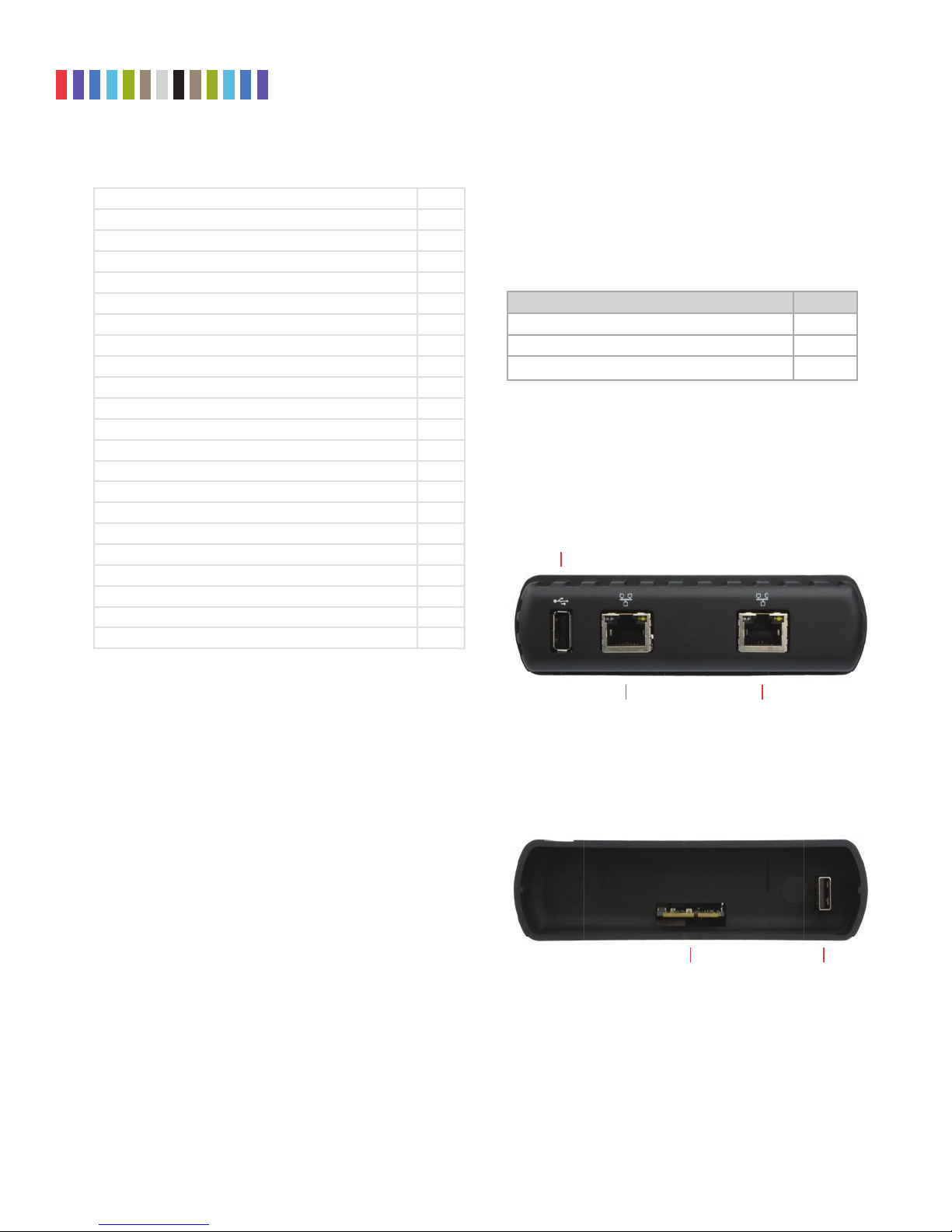
1.2 IDENTIFYING PARTS
Take a moment to familiarize yourself with the parts of the
product. This will help you to better understand the following
instructions.
FRONT
USB 2.0 Port
Protecting Your Digital Assets
RJ45 Gigabit
Ethernet Connection
RJ45 Gigabit
Ethernet Connection
BACK
Expansion Module
Connector
TM
USB 2.0
Passthrough
Page 3

Ditto Network Tap Module User Manual
3
1.3 HOW TO USE THE NETWORK TAP MODULE
Use the Network Tap Module with the Source Inputs side of your Ditto or Ditto DX to intercept network
traffic that travels between the target computer and the network it is connected to. The available con
nections include two RJ45 gigabit Ethernet ports and a USB 2.0 port for use with USB storage devices, a
keyboard, or a wifi adapter. Both RJ45 ports are direction agnostic, so it doesn’t matter which port is used
to connect to the network and which is used to connect to the target computer.
-
NOTE
CRU recommends that you switch the power off to your Ditto product when you add or remove a
device from it in order to avoid disk damage and data corruption.
2 SETUP
a. With your Ditto product powered off, insert the Network Tap Module into the Source Inputs side of your
Ditto product.
b. Connect an Ethernet cable connected to your network into one of the RJ45 gigabit Ethernet ports on the
expansion module.
c. Connect another Ethernet cable to the remaining RJ45 gigabit Ethernet port on the expansion module and
connect the other end to your computer.
d. Turn your Ditto product on.
You are ready to start using your Ditto product with the Network Tap Module! You may access its settings
via the Browser Interface (see your Ditto product’s user manual) or via the Front Panel (see Section 3.5).
3 NETWORK TAP FUNCTIONALITY
The Network Tap Module adds several new actions and functions to the Ditto and Ditto DX browser interface
and Front Panel. They are listed below:
3.1 HOME SCREEN
The Network Tap Module adds a “Network Capture” action to Action panel on the “Home” screen of the
Browser Interface. Click on the Home tab to access the “Home” screen from any other area of the Browser
Interface.
The “Network Capture” action provides two methods of capturing network traffic that can be combined and
used simultaneously if you wish. The first method captures network traffic and stores it in a series of incre
mented PCAP files on the local target destination. The second method captures network traffic in real-time
and outputs it to a remote monitor that uses a third-party Wireshark network protocol analyzer. Instructions
for both methods as well as instructions for using them simultaneously can be found below.
3.1.1 PCAP Network Capture
a. Using the Browser Interface, select Network Capture from the “Action to Perform” drop-down
box.
b. Select the network capture filter from the “Network Capture Filter” drop-down box or type in the
ports you wish to capture in the text box directly below. Use the syntax “port ## or ##” without
quotes (e.g. port 80 or 81 or 443).
c. Select “Network Tap” from the “Interface” drop-down box.
Protecting Your Digital Assets
TM
-
Page 4

Ditto Network Tap Module User Manual
4
d. Select the media from the “Destination” drop-down box that you want Network Tap Module to save
your captured data.
e. Select the partition on the destination media you want to capture to from the “Partition” drop-down
box.
f. Bypass “Live Network Capture” and leave it disabled.
g. Click the Start button to begin capturing network data. When you are fi nished, click the Stop
button.
You can view the log of the network capture action by scrolling down to the “System Log” panel on
the “Home” screen. Find and click on the latest link, which will be denoted by a fi lename with a date/
timestamp format: “S_yyyymmddhhmmss”. Alternatively, you can click on the Logs button from the
top menu bar.
You can view the data retrieved from the network capture action by examining the destination media,
which will contain a folder named with the same data/timestamp format: “S_yyyymmddhhmmss”. This
folder includes the PCAP fi les containing the captured data, an XML fi le containing the log information of
the network capture, and—if hashing is enabled—a TXT fi le that contains each of the generated PCAP
fi les’ MD5 or SHA-1 hash value (see Section 5.1.2 to enable hashing).
3.1.2 Live Network Capture
a. Using the Browser Interface, select Network Capture from the “Action to Perform” drop-down
box.
b. Select the network capture fi lter from the “Network Capture Filter” drop-down box or type in the
ports you wish to capture in the text box directly below. Use the syntax “port ## or ##” without
quotes (e.g. port 80 or 81 or 443)
c. Disregard the “Interface” and “Destination” drop-down boxes.
d. Ensure your third party Wireshark network protocol analyzer is standing by to receive data. If you
need help in confi guring Wireshark itself, click the
ture” for a link to Wireshark’s remote capture documentation.
e. Click the Enable button next to “Live Network Capture” to turn live network capture on. When you
are fi nished capturing network traffi c, click the Disable button.
STOP!
Do NOT click the Start button! This button actually enables the PCAP network capture function that
captures network traffi c to your local destination media. It does NOT enable live network capture.
Figure 1. The “Action” section on the “Home” screen, showing
the options available for the “Network Capture” action.
Information icon next to “Live Network Cap-
Protecting Your Digital Assets
TM
Page 5

Ditto Network Tap Module User Manual
5
3.1.3 Simultaneous PCAP and Live Network Capture
a. Using the Browser Interface, select Network Capture from the “Action to Perform” drop-down
box.
b. Select the network capture fi lter from the “Network Capture Filter” drop-down box or type in the
ports you wish to capture in the text box directly below. Use the syntax “port ## or ##” without
quotes (e.g. port 80 or 81 or 443).
c. Select “Network Tap” from the “Interface” drop-down box.
d. Select the local media from the “Destination” drop-down box that you want Network Tap Module to
save your captured data to as a series of incremented PCAP fi les.
e. Select the partition on the local destination media you want to capture to from the “Partition” drop-
down box.
f. Ensure your third party Wireshark network protocol analyzer is standing by to receive data. If you
need help in confi guring Wireshark itself, click the
ture” for a link to Wireshark’s remote capture documentation.
g. Click the Enable button next to “Live Network Capture” to turn live network capture on. When you
are fi nished capturing network traffi c, click the Disable button.
h. Click the Start button to begin capturing network data to your local destination media. When you
are fi nished, click the Stop button.
Information icon next to “Live Network Cap-
You can view the log of the PCAP network capture action by scrolling down to the “System Log” panel
on the “Home” screen. Find and click on the latest link, which will be denoted by a fi lename with a date/
timestamp format: “S_yyyymmddhhmmss”. Alternatively, you can click on the Logs button from the
top menu bar.
You can view the data retrieved from the PCAP network capture action by examining the destina-
tion media, which will contain a folder named with the same data/timestamp format: “S_yyyymmd-
dhhmmss”. This folder includes the PCAP fi les containing the captured data, an XML fi le containing the
log information of the network capture, and—if hashing is enabled—a TXT fi le that contains each of the
generated PCAP fi les’ MD5 or SHA-1 hash value (see Section 5.1.2 to enable hashing).
3.2 CONFIGURE SCREEN
The “Confi gure” screen now has several new options that modify the way the Network Tap Interface func-
tions to suit your specifi c needs. These options are listed below. Click on the Confi gure tab to access the
“Confi gure” screen from the Browser Interface.
3.2.1 System
The “System” tab allows you to view and customize the following new settings. This information is
also displayed in the “System Settings” panel on the “Home” screen. When you are fi nished, click the
Commit Changes button to save the changes.
Typical Settings
• Network Capture Filter: Sets the default network capture fi lter for the “Network Capture”
action. The available fi lters are All, HTTP, E-Mail, SSH, or any available custom fi lter that you
Protecting Your Digital Assets
TM
Page 6

Ditto Network Tap Module User Manual
6
have saved onto the currently installed SD card. To create your own custom fi lter, see Section
11.3.
• Hash Type: Sets the default hash algorithm that will be used for disk verifi cation, the “Hash
Disk” action, and now also PCAP fi le verifi cation.
Available algorithms: None, MD5, SHA-1, SHA-256, MD5 & SHA-1, MD5 (SW) & SHA-1, MD5 &
SHA-1 (SW), MD5 & SHA256, MD5 (SW) & SHA-256, MD5 & SHA-256 (SW), MD5 (SW), SHA-1
(SW), MD5 (SW) & SHA-1 (SW), SHA-1 (SW) & MD5, SHA-1 (SW) & SHA-256, SHA-256 (SW) &
MD5, SHA-256 (SW), or SHA-512 (SW).
3.3 NETWORK CAPTURE
The new “Network Capture” tab allows you to view and customize the following new settings for all net-
work capture actions. When you are fi nished, click the Commit Changes button to save the changes.
3.3.1 Network Capture Settings
• Image File Count: Specifi es the maximum number of image fi les that are created on the des-
tination disk. When the number is reached, the Network Tap Module will begin overwriting the
oldest fi le on the disk for each new fi le that is created. Set this to ‘0’ to fi ll the disk until it reaches
capacity.
• Image File Segment Size: Allows you to specify the size in bytes that each image fi le should be.
The minimum size is 1M (megabyte). The maximum size is limited by the target fi le system. If this
fi eld is left blank, the maximum size will be used. When the specifi ed size is reached, a new image
fi le is created. Click the
Information icon for more information.
• Snap Size: Allows you to capture up to the specifi ed amount of bytes of each packet of data. Click
Information icon for more information.
the
• Dropped Pkt Log Interval: Allows you to specify the time interval in minutes of how often the
Network Tap Module writes its accumulated dropped packet information to the Action log. Setting
this value to ‘0’ disables packet loss reporting. Click the
Information icon for more information.
Figure 2. The “Network Capture” tab on the “Confi gure” screen.
Protecting Your Digital Assets
TM
Page 7

Ditto Network Tap Module User Manual
7
3.3.2 Live Capture Settings
When enabled, this service runs continuously in the background and streams captured data in realtime
over the network to a remote monitor using the third-party Wireshark network protocol analyzer. See
Section 4.1.1 for more information.
• Auto Start: Set this value to ‘Enabled’ to turn on live capture as soon as the Network Tap Module
is powered on. Set this value to ‘Disabled’ if you want the user to choose when to start the live
capture service in the Browser Interface.
• Port: This is the port that the Network Tap Module uses to talk to the third-party network protocol
analyzer software. The default port is 2002.
• Username: The username used by the third-party network protocol analyzer software.
• Password: The password used by the third-party network protocol analyzer software.
3.3.3 Advanced Settings
• Buffer Size: Sets the the buffer size used by the Network Tap Module during a network capture
action. The minimum size is 512K (kilobytes). The default size of 16M (megabyte) works best for
most use cases. Click the
• MTU: If you are using the Network Tap Module on a network that’s confi gured to a non-standard
maximum transmission unit size (e.g. it uses jumbo frames), then set this fi eld to match that value.
Most Ethernet LANs will use the standard MTU of 1500. The commonly accepted range for a valid
MTU is 68 to 65,535 as defi ned in RFC 791. Click the
Information icon for more information.
Information icon for more information.
• Link Speed: Allows you to set the Ethernet connection speed throughput. In most cases, ‘Auto
Negotiate’ will work. If you experience problems staying connected, you may need to change the
speed to match what your network’s capabilities are.
3.4 USING AND CONFIGURING NETWORK CAPTURE FILTERS
Insert the SD Card containing your network capture fi lter(s) into the Network Tap Module and your custom
network capture fi lters will become available in the “Network Capture Filter” drop-down box when con-
fi guring a “Network Capture” action. You may also add subdirectories that contain one or more network
capture fi lter XML fi les to the DittoNetCapFilter directory.
To add or edit your own network capture fi lter, choose the way that works best for your usage scenario.
3.4.1 Filter Creation Via Web Browser
a. Insert the SD Card into the SDCard slot on the rear of the Network Tap Module.
b. Using the Browser Interface, select Network Capture from the “Action to Perform” drop-down
box.
c. If you are editing an existing network capture fi lter that you created, select it from the “Network
Capture Filter” drop-down box.
d. Type in the ports you wish to capture in your network capture fi lter in the text box directly below the
“Network Capture Filter” drop-down box (see Figure 3). Use the word ‘or’ to separate each port.
e. Click the Save button. The “Save Network Capture Filter” dialog box will pop up (see Figure 4).
Protecting Your Digital Assets
TM
Page 8

Ditto Network Tap Module User Manual
8
f. Use the “Select Filter...” drop-down box and select New Filter... to create a new fi lter or select an
existing fi lter to overwrite it.
g. Use the “Select File...” drop-down box and select New File... to create a new XML fi le, or select an
existing fi le to add your network capture fi lter to the fi le.
h. Type the desired fi lename into the “File Name” text box.
i. Type the desired name of the fi lter into the “Filter Name” text box.
j. Click the Save button to save the fi lter.
3.4.2 Manual Filter Creation
To manually create a network capture fi lter on an SD Card, you must manually create a DittoNetCap-
Filter directory on your SDCard fi rst. Then you can add one or more network capture fi lter XML fi les to
that directory.
Create an XML fi le using the following structure and place it within the DittoNetCapFilter directory on
your SDCard:
<?xml version=”1.0” encoding=”UTF-8”?>
<!-- All attributes must be in single quotes if they contain double quotes.
-->
<dittoNetCapFilter
xmlns:xsi=”http://www.w3.org/2001/XMLSchema-instance”
xsi:noNamespaceSchemaLocation=”netCapFilter.xsd”
>
<fi lter title=”All”>insert port numbers here, separated by the word‘or’</
fi lter>
</dittoNetCapFilter>
The name of the network capture fi lter XML fi le can be any legal fi le name with an XML fi le extension.
Each XML fi le may contain one or more <fi lter title=”...”> blocks. The fi lter block’s title will appear at
the bottom of the “Network Capture Filter” selection list prepended with “SDCard/” followed by the
subdirectory’s name, if any.
NOTE
You cannot remove existing selections from the Network Capture Filter list.
Figure 3. The “Action” screen, showing where to type in the
ports that you wish to capture with the “Network Capture”
action.
Protecting Your Digital Assets
TM
Figure 4. The “Save Network Capture Filter”
dialog box lets you save custom network
capture fi lters.
Page 9

Ditto Network Tap Module User Manual
9
To download an XML Schema that can be used to validate your network capture fi lter XML fi le, type
the following into the address bar of an Internet browser, where <IP Address> is the IP address of your
Network Tap Module: http://<IP Address>/data/DittoNetCapFilter/netCapFilter.xsd
Click the
fi lters.
Information icon for a link to a site that describes the syntax supported by network capture
3.5 USING THE FRONT PANEL INTERFACE IN STANDALONE MODE
The Front Panel interface now allows you to perform a network capture and modify various settings about
its functionality. These new settings are listed herein.
3.5.1 Settings
The “Settings” screen allows you to view and customize the following new settings, which are grouped
into three subsections. These settings will be the default settings used in any actions performed.
NOTE
The System Settings below cannot be modifi ed if the Front Panel user account does not have full
access to the “Confi g” permission. See your Ditto product’s user manual for information on how to
customize the Front Panel user account.
System Settings
• Hash Type: Sets the default hash algorithm that will be used for disk verifi cation, the “Hash
Disk” action, and now also PCAP fi le verifi cation.
Available algorithms: None, MD5, SHA-1, SHA-256, MD5 & SHA-1, MD5 (SW) & SHA-1, MD5 &
SHA-1 (SW), MD5 & SHA256, MD5 (SW) & SHA-256, MD5 & SHA-256 (SW), MD5 (SW), SHA-1
(SW), MD5 (SW) & SHA-1 (SW), SHA-1 (SW) & MD5, SHA-1 (SW) & SHA-256, SHA-256 (SW) &
MD5, SHA-256 (SW), or SHA-512 (SW).
NetCap Settings
This new section allows you to modify the settings that govern network capture actions.
• NetCap Filter: Sets the default network capture fi lter for the “Network Capture” action. The
available fi lters are All, HTTP, E-Mail, SSH, or any available custom fi lter that you have saved
onto the currently installed SD card. To create your own custom fi lter, see Section 3.4.
• NetCap File Count: Specifi es the maximum number of image fi les (based on image fi le seg-
ment size, see Section 3.3.1) that are created on the destination disk. When the number is
reached, the Network Tap Module will begin overwriting the oldest fi le on the disk for each
new fi le that is created. Set this to ‘0’ to fi ll the disk until it reaches capacity.
• NetCap Snap Size: Allows you to capture up to the specifi ed amount of bytes of each packet
of data.
• NetCap Pkt Log Inter: Allows you to specify the time interval in minutes of how often the Net-
work Tap Module writes its accumulated dropped packet information to the Action log. Setting
this value to ‘0’ disables packet loss reporting.
• Live Capture: This service runs continuously in the background and streams captured data in
realtime over the network to a remote monitor using the third-party Wireshark network protocol
analyzer. See Section 3.1.2 for more information.
Protecting Your Digital Assets
TM
Page 10

Ditto Network Tap Module User Manual
10
• LiveCap Auto Start: Set this value to ‘Enabled’ to turn on live capture as soon as the Network
Tap Module is powered on. Set this value to ‘Disabled’ if you want the user to choose when to
start the live capture service in the Browser Interface.
• NetCap MTU: If you are using the Network Tap Module on a network that’s configured to a
non-standard maximum transmission unit size (e.g. it uses jumbo frames), then set this field
to match that value. Most Ethernet LANs will use the standard MTU of 1500. The commonly
accepted range for a valid MTU is 68 to 65,535 as defined in RFC 791.
• NetCap Link Speed: Allows you to set the Ethernet connection speed throughput. In most
cases, ‘Auto Negotiate’ will work. If you experience problems staying connected, you may need
to change the speed to match what your network’s capabilities are.
4 TECHNICAL SPECIFICATIONS
Product Name Ditto Network Tap Module
Ditto Family Compatibility Ditto Forensic FieldStation, Ditto DX Forensic FieldStation
Data Interface Types &
Speeds
Supported Drive Types External USB HDDs, SSDs and media card readers
Data Connectors
1000BASE-T EtherNet: up to 1 Gbps
USB 2.0: up to 480 Mbps
Two (2) 1000BASE-T Ethernet connectors
One (1) USB 2.0 connectors
External material All-metal construction
Operating Humidity 5% to 95%, non-condensing
Power over Ethernet PoE+ (30W)
EMI Standard: FCC Part 15 Class A
Compliance
EMC Standard: EN55024, EN55032
CE, RoHS
Product Weight Standalone: 0.5 pounds (0.23 kg)
Product Dimensions 2.81in W x 4.94in L x 1.43in H (71.3mm W x 125.6mm L x 36.4mm H)
Your investment in CRU products is backed up by our free technical sup-
Technical Support
port for the lifetime of the product. Contact us through our website, www.
cru-inc.com/support or call us at 1-800-260-9800 or +1-360-816-1800.
Protecting Your Digital Assets
TM
Page 11

© 2018 CRU Acquisition Group, LLC. ALL RIGHTS RESERVED.
This User Manual contains proprietary content of CRU Acquisition Group, LLC (“CRU”) which is protected by copyright, trademark, and other intellectual
property rights.
Use of this User Manual is governed by a license granted exclusively by CRU (the “License”). Thus, except as otherwise expressly permitted by that
License, no part of this User Manual may be reproduced (by photocopying or otherwise), transmitted, stored (in a database, retrieval system, or otherwise), or otherwise used through any means without the prior express written permission of CRU.
Use of the full Network Tap Module product is subject to all of the terms and conditions of this User Manual and the above referenced License.
CRU®, WiebeTech®, and Ditto® (collectively, the “Trademarks”) are trademarks owned by CRU and are protected under trademark law. This User Manual
does not grant any user of this document any right to use any of the Trademarks.
Product Warranty
CRU warrants this product to be free of significant defects in material and workmanship for a period of three years from the original date of purchase.
CRU’s warranty is nontransferable and is limited to the original purchaser.
Limitation of Liability
The warranties set forth in this agreement replace all other warranties. CRU expressly disclaims all other warranties, including but not limited to, the
implied warranties of merchantability and fitness for a particular purpose and non-infringement of third-party rights with respect to the documentation
and hardware. No CRU dealer, agent, or employee is authorized to make any modification, extension, or addition to this warranty. In no event will CRU
or its suppliers be liable for any costs of procurement of substitute products or services, lost profits, loss of information or data, computer malfunction,
or any other special, indirect, consequential, or incidental damages arising in any way out of the sale of, use of, or inability to use any CRU product or
service, even if CRU has been advised of the possibility of such damages. In no case shall CRU’s liability exceed the actual money paid for the products
at issue. CRU reserves the right to make modifications and additions to this product without notice or taking on additional liability.
FCC Compliance Statement: “This device complies with Part 15 of the FCC rules. Operation is subject to the following two conditions: (1) This device
may not cause harmful interference, and (2) this device must accept any interference received, including interference that may cause undesired operation.”
This equipment has been tested and found to comply with the limits for a Class A digital device, pursuant to Part 15 of the FCC Rules. These limits are
designed to provide reasonable protection against harmful interference when the equipment is operated in a commercial environment. This equipment
generates, uses, and can radiate radio frequency energy and, if not installed and used in accordance with the instruction manual, may cause harmful
interference to radio communications. Operation of this equipment in a residential area is likely to cause harmful interference in which case the user will
be required to correct the interference at this own expense.
In the event that you experience Radio Frequency Interference, you should take the following steps to resolve the problem:
1) Ensure that the case of your attached drive is grounded.
2) Use a data cable with RFI reducing ferrites on each end.
3) Use a power supply with an RFI reducing ferrite approximately 5 inches from the DC plug.
4) Reorient or relocate the receiving antenna.
Part Number: A9-000-0061 Rev 1.0 1000 SE Tech Center Drive, Suite 160, Vancouver, WA 98683
For more information,
visit the CRU web site.
www.cru-inc.com
 Loading...